Table of Contents
Advertisement
Quick Links
Advertisement
Table of Contents

Summary of Contents for Topcon Luminance Colorimeter BM-5AC
- Page 1 INSTRUCTION MANUAL Luminance Colorimeter Rev.7...
-
Page 3: Introduction
・ To maintain measurement precision, perform calibration and maintenance on average once a year. When performing calibration, consult with your dealer or Topcon Technohouse Corporation. ・ When requesting calibration, put this instrument in its carrying case, and then put it in a cardboard box packed with shock-absorbing material before sending it. -
Page 4: Safety Indications
Safety Indications Warnings and Cautions are indicated on this instrument and in the instruction manual to prevent injury to users and others, prevent damage to property or the like, and to ensure safe use of this instrument. After fully understanding the following indications and symbols, carefully read the section "Safety Precautions,"... -
Page 5: Safety Precautions
If you notice strange noise, smell or smoke from this instrument, immediately turn the instrument OFF and unplug the AC adapter from the power outlet. Continued use of this instrument in this state might cause fire. Mandatory Contact your dealer or Topcon Technohouse Corporation. - Page 6 ・ TOPCON does not assume any liability due to collateral damage (loss of business profit, interruption of work, etc.) from the use of or inoperability of this instrument. ・ TOPCON does not assume any liability for damage that occurs due to use other than that explained in this instruction manual.
-
Page 7: Table Of Contents
Table of Contents Introduction ..........................1 Safety Indications ........................2 Safety Precautions ........................3 Notation Rules Used in This Manual ................... 8 1. Before Use ........................9 Checking the Unit and Supplied Parts ................9 Part Names and Functions ..................... 10 Preparation ........................ - Page 8 Selecting Filters in the Tristimulus Value Fixed Mode ......................67 3.2.10 Selecting the Analog Output Response Speed (Analog Waveform Observation) ..........68 3.2.11 Buzzer Sound ....................................... 69 3.2.12 Communication Format ..................................69 3.2.13 Maintenance Recommended Message ............................70 3.2.14 Color Adjustment ......................................70 3.2.15 Range Retry Count ....................................
- Page 9 5. USB Driver ......................... 88 Appendix ........................90 Specifications ..........................90 Appended Tables ........................94 System Diagrams ........................95 External Dimensions ......................... 96 Internal Calculation Processing ....................97 Terminology ..........................99...
-
Page 10: Notation Rules Used In This Manual
Notation Rules Used in This Manual The following notation rules are used in this manual. Notation Explanation [MODE], [UP] Indicates panel switches or titles of screens displayed on the display. ☞ 「」 Indicates a reference location in the manual. ☞ 『』... -
Page 11: Before Use
1.1 Checking the Unit and Supplied Parts Make sure that the main unit and all of the accessories are in proper order. If there are any missing parts, contact your dealer or Topcon Technohouse Corporation. ・ Main unit ・ Objective lens cap ・... -
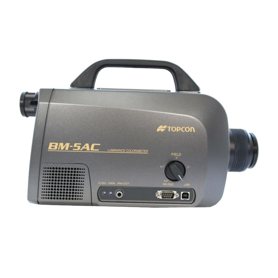
Page 12: Part Names And Functions
1. Before Use 1.2 Part Names and Functions ■ Main Unit Handle Viewfinder shutter selection knob Measuring field selector knob Diopter adjustment ring Eyepiece USB connector RS-232C connector Display Analog output connector Panel switches Analog output adjustment control (gain) Analog output adjustment control (offset) Fan motor (suction inlet) Name Function... - Page 13 1. Before Use Connector used for observing analog output. The output of the photo detector can be observed as a voltage value. Analog output connector ☞ "2.2.5 How to Use the Analog Output Connector" Analog output adjustment control Control for adjusting analog output gain. (gain) The maximum output voltage value is approx.
- Page 14 1. Before Use ■ Panel Switches Display Panel switches SINGLE/AVE. switch (CHANGE switch) NORMAL/FINE RUN/HOLD switch switch (ROTATION switch) (ENTER switch) NORMAL SINGLE F I N E A V E . HOLD ENTER ROTATION CHANGE MODE LAMP CALIB CALIBRATION MODE switch switch SHIFT FUNCTION...
- Page 15 1. Before Use Switches the color coordinate system displayed on the display. When this switch pressed with measurement stopped (MEAS./HOLD switch set to HOLD), the color coordinate system displayed on the display is switched in the following order: MODE switch xy/L →...
- Page 16 1. Before Use ■ Display ・ Top screen This screen is displayed when the power is turned ON. * * S t a r t B M - 5 A C * * * * V e r * . * * * * ・...
-
Page 17: Preparation
1. Before Use 1.3 Preparation ■ Connecting the AC Adapter Be sure to use the supplied AC adapter or a separately sold and authorized AC adapter. AC adapter failure may result in fire or electric shock. Mandatory Remove dust or moisture from the AC adapter plug. Failure to do so might cause fire. - Page 18 1. Before Use Plug the AC adapter plug into the power outlet.
- Page 19 1. Before Use ■ Connecting to a PC When connecting the BM-5AC to a PC, use an RS-232C cable or USB cable. When using an RS- 232C cable, use a DOS/V PC-compatible straight cable. Up to 16 instruments can be connected to a single PC using the USB cable.
- Page 20 1. Before Use ■ Collimation of the Measurement Object Do not look directly at bright lights such as the sun or light bulb filaments. Doing so might damage your eyes. Prohibited Use only specified screws when using the tripod screw and screw holes for jig attachment.
- Page 21 1. Before Use ■ Turning the Power ON/OFF Warming Up Recommendation ・ Be sure to warm up the instrument for at least 30 minutes so that measurement Request can be performed at high precision. ・ After warming up has ended, be sure to press the CALIB switch to execute calibration.
-
Page 22: Maintenance Recommended Message
1. Before Use Memo ・ If it has been 1 year or more since calibration was last performed by a Topcon factory, a screen recommending maintenance is displayed before calibration is executed. Display of maintenance recommendation screen ☞ "1.4 Maintenance Recommended Message"... -
Page 23: Error Display
Check the measuring field selector switch, and make sure that the measuring field is set properly. This is displayed when the battery in the instrument should be replaced. To replace the battery, contact your dealer or a Topcon Technohouse Low BAT office. - Page 24 1. Before Use *** ERROR *** Initialization communication error. Internal The power OFF then back ON again. Communication...
-
Page 25: Measurement Operation
2.Measurement Operation 2.Measurement Operation 2.1 Basic Measurement This section describes basic measurement methods. 2.1.1 Measuring the Light Source Color The following describes the procedure for measuring the light source color. Turn the instrument ON, and display the measurement screen. F 2 . 0 A B S K 0 0 G 0 0 - 0 x = 0 . -
Page 26: Measuring Object Color
Correct measurement results cannot be obtained if the luminance factor is Request set incorrectly. ・ Use a Topcon standard white board WS-3. Place the white board under the light source, and press the [RUN/HOLD] switch to measure the luminance and chromaticity of the light source. After measurement ends, the measurement results are displayed for about 3 seconds, and sample measurement is started. -
Page 27: Absolute Value Measurement
2.Measurement Operation 2.1.3 Absolute Value Measurement The following describes the procedure for measuring absolute values. Set to the absolute value measurement mode (ABSOLUTE) in the function mode. ☞ "3.1.1 Entering/Returning from the Function Mode" Press the [RUN/HOLD] switch to start measurement. To stop measurement, press the [RUN/HOLD] switch. -
Page 28: Measurement Result Display Mode
2.Measurement Operation 2.1.5 Measurement Result Display Mode When the display is in the HOLD mode ([HOLD] on the RUN/HOLD switch is blinking), you can change to the measurement result display mode by pressing the MODE switch. Each press switches the display as follows: - Light Source Color - - Object Color - Chromaticity xy Luminance L... -
Page 29: Various Measurement Examples
2.Measurement Operation 2.2 Various Measurement Examples This section introduces various examples of measurement. Use these examples as references when using this instrument. 2.2.1 Measuring a Light Source With Directivity Data having good reproducibility sometimes cannot be obtained when observing a light source with high directivity such as an LED or an uneven light source. -
Page 30: Using The Instrument In Another System
2.Measurement Operation 2.2.3 Using the Instrument in Another System When using the instrument in another system such as an XY stage, install it on the system using the jig attachment screws on the base of the instrument. Also, connect the instrument to a PC using the RS-232C or USB interface. When using the unit in a system, refer to the following. - Page 31 2.Measurement Operation Next, place the BM-5AC to be corrected in the location where the reference instrument is placed, and measure the same light source. Light source BM-5AC The correction factor of the BM-5AC to be corrected is calculated based on the data of the reference instrument and the data of the BM-5AC to be corrected.
- Page 32 2.Measurement Operation Press the [ROTATION] switch, select "MEASURE REFERNCE" ("*" is displayed), and press the [ENTER] button. MEASURE REFERNCE : Perform measurement on the reference instrument, and write the measurement data to the BM-5AC to be corrected. MEASURE FACTOR : Measurement is performed using the BM-5AC to be corrected, then the correction factor is calculated based on data obtained by "MEASURE REFERNCE".
- Page 33 2.Measurement Operation Press the [CHANGE] switch. The [*DIRECT-CONN FACTOR*] screen is displayed. * D I R E C T - C O N N F A C T O R * * M E A S U R E R E F E R E N C E E X I T A L L F A C T O R C L E A R R E F 1 1...
- Page 34 2.Measurement Operation Specify a number to write the data for the BM-5AC to be corrected. Select a number containing the data of the reference instrument, and press the [CHANGE] button. Memo ・ If the data "REF" of the reference instrument is not entered at the number to write the data to, measurement cannot be performed.
- Page 35 2.Measurement Operation Press the [ENTER] button to display the correction factor screen. K 1 1 K X = 9 . 3 4 3 E - 0 1 C S E T T K Y = 9 . 5 8 9 E - 0 1 C = S E T K Z = 9 .
-
Page 36: Using The Analog Output Connector
2.Measurement Operation 2.2.5 Using the Analog Output Connector Use the analog output connector to observe the characteristics of a flashing light source etc.. This connector is connected to an oscilloscope, for example, so that characteristics can be observed. Example) Rise and fall response characteristics, frequency, etc. of a flashing light source Such characteristics are observed by selecting and fixing one of the built-in tristimulus value filters X / Y / Z, and extracting analog output from the photo detector from the analog output... - Page 37 2.Measurement Operation ■ Analog output response speed The analog output response speed differs depending on the measurement range used. ☞ Response speed "Appendix: Analog Output Response Speed" To observe the characteristics of a flashing light source, set the analog output response speed in the function mode to FAST.
-
Page 38: Various Settings
3. Various Settings 3. Various Settings 3.1 Function Mode The function mode is for checking or changing various data or settings that are stored in the instrument's memory. 3.1.1 Entering/Returning from Function Mode Entering and returning from the function mode is performed using the [FUNCTION] button. Press the button once, to enter Function mode, and press it again to return from Function mode. -
Page 39: Displaying Data/Setting Items
3. Various Settings 3.1.2 Displaying Data/Setting Items In the function mode, each press of the [ENTER] button changes the type of data/setting item that is displayed. Press the [ENTER] button until the data/setting item to be checked or changed is displayed. -
Page 40: Display Screens
3. Various Settings 3.1.3 Display Screens The follows shows and describes the screens that are displayed in the function mode. Pressing the [ENTER] button displays the next screen. For details on each screen, see the details ☞ "x.x ○○○○". ■ Selecting light source/object color S O U R C E / O B J E C T Select light source color "SOURCE"... - Page 41 3. Various Settings ■ Selecting the measurement range R S - A U T O M A N U A L Select the AUTO range AUTO/manual range MANUAL. B A U D T R A T E = 3 8 4 0 0 E - 0 1 * Details ☞...
- Page 42 3. Various Settings ■ Setting the color adjustment C O L O R A D J U S T M E N T B A U D T R A T E = 3 8 4 0 0 E - 0 1 * Use this when measurement is done on condition that L E N G C H Y priority is given to the correlativity with the old models.
-
Page 43: Entering Numerical Values
3. Various Settings 3.1.4 Entering Numerical Values The following describes the procedure for entering numerical values, for example, when setting the luminance factor of the white board, or when entering luminance chromaticity as the reference data for correction factors. The procedure for entering numerical values in the function mode is the same for all setting items. The following describes an example of how to set numerical values in the function mode when setting the luminance factor of the white board. -
Page 44: Detailed Explanation Of Function Mode
3. Various Settings 3.2 Detailed Explanation of Function Mode 3.2.1 Selecting Light Source/Object Color The light source color and object color can be switched according to the measurement target. S O U R C E / O B J E C T C S E T T K Y = 9 . - Page 45 3. Various Settings Step 2 Setting the luminance factor of the white board The following white board luminance factor setting screen is displayed. Use the [CHANGE], [ROTATION] or [SHIFT] switch to set the luminance factor. The luminance factor can be input from 80% to 120%. ☞...
- Page 46 3. Various Settings Step 3 Setting the luminance factor of white board measurement When the chromaticity xy of the illumination light source used when measuring object color is already known, object color can be measured more accurately by applying correction to the measurement results of the white board (illumination light source).
- Page 47 3. Various Settings Change the luminance factor of the white board, set the correction factor in white board measurement, and apply the changes by the [ENTER] switch. The following message is displayed. Place the white board under the illumination light source for measuring the object color, and press the [RUN/HOLD] switch to measure white board.
-
Page 48: Selecting Measurement Of Absolute Values/Difference
3. Various Settings 3.2.2 Selecting Measurement of Absolute Values/Difference With this instrument, it is possible to measure absolute values and the difference from reference data. K S O U A B S / D I F E C T 0 1 C S E T T K Y = 9 . -
Page 49: Setting The Averaging Count
3. Various Settings Measurement results display S T A N D A R D S A M P L E P l e a s e 0 . 3 1 2 7 3 + 0 0 * t h e Y S M 0 . -
Page 50: Correction Factor
3. Various Settings 3.2.4 Correction Factor Measurement results can be corrected by applying the correction factor on the measurement result. "Correction factor" is a function for correcting measurement results according to an internal program. Correction factors can be registered in the following 3 ways: 1 By directly entering KX, KY, KZ 2 By entering luminance chromaticity and performing measurement to obtain KX, KY, KZ 3 By connecting to another instrument and comparing measurement results to obtain KX,... - Page 51 3. Various Settings 3.2.4.1 Correction Factor Menu Screen ■When FACTOR A is selected The next screen is the menu screen that is displayed when the correction factor group FACTOR A is selected. F A C T O R C T O R M A A / U B E 0 0 * D I S P &...
- Page 52 3. Various Settings ■When FACTOR B is selected The next screen is the menu screen that is displayed when the correction factor group FACTOR B is selected. Use this menu screen for using the direct correction function to obtained the correction function. * D I R E C T - C O N N F A C T O R * P l D...
- Page 53 3. Various Settings 3.2.4.2 Entering Correction Factors The following describes the procedure for entering the correction factor. 1 Display the following screen in the function mode. 2 A V F A C T O R E 0 0 P l e a s e x = e 0 . 0 1 8 3 3 + 0 0 * t h e Y S A F A C T O R 7 t h e n *...
- Page 54 3. Various Settings Press the [CHANGE] switch to display the correction factor entry menu screen. F A C T O R I N P U T / U B E 0 0 * P l D D I R E C T D A T A 8 O F F 0 0 * T * I R E F .
- Page 55 3. Various Settings ■ Entering target luminance and chromaticity data to calculate the correction factors based on measurement by that data 1 Press the [ROTATION] switch to move the selection cursor "*" to "REF.&MEASURE", and then apply the setting with the [ENTER] switch. F A C T O R I N P U T / U B E 0 0 *...
- Page 56 3. Various Settings 6 Press the [ROTATION] switch to move the selection cursor "*" to "BACK". Then apply pressing the [ENTER] switch to apply the setting, and return to the correction factor display screen. K 0 1 K X = 1 .
- Page 57 3. Various Settings 3.2.4.3 Checking/Setting Correction Factors The values of the currently registered correction factors are displayed. If there are no correction factors registered, "NO DATA" is displayed. "SET" is displayed underneath the number of the correction factor currently being used. When no correction factors are registered K 0 1 T D K X = C 1 .
- Page 58 3. Various Settings - Reference Data - The reference data that was entered for calculating the correction factor is displayed. R E F 0 1 0 . 4 4 7 6 + 0 0 * P l K X = R K 0 .
- Page 59 3. Various Settings 3.2.4.4 Clearing Correction Factors 1 Display the correction factor menu screen. F A C T O R C T O R M A A / U B E 0 0 * D I S P & S E T .
-
Page 60: Area Correction Factor
3. Various Settings 3.2.5 Area Correction Factor "Area correction factor" is a function for correcting measurement results that fall within an arbitrary area when that area is specified on the xy and u'v' chromaticity diagrams. Memo ・ There are two ways of registering area correction factors, by using the CS-900A application software (sold separately) or by making a communication program by referring to the list of communication commands. - Page 61 3. Various Settings For example, to perform measurement with different correction factors applied on each color of R (red), G (green), B (blue), and W (white), correction factors for each individual color can be applied by specifying the chromaticity colors of R (red), G (green), B (blue), and W (white). Specified chromaticity area 0.1 0.2 0.3 0.4 0.5 0.6 0.7 0.8 ・...
- Page 62 3. Various Settings 3.2.5.1 Setting the Area Correction Factor Group The following describes the procedure for changing the area correction factor group setting. Display the following screen in the function mode. F A C T O R G R O U P E + 0 0 P l S E T L K Y = C 1 .
- Page 63 3. Various Settings 3.2.5.2 Displaying the Area Correction Factor The following describes the procedure for displaying the chromaticity area currently set for an area correction factor group. Press the [CHANGE] switch. The currently set area correction group is displayed. G R O U P S E T O U P E + 0 0 P l S E T L K Y = C 1 .
-
Page 64: Selecting The Interface
3. Various Settings 3.2.6 Selecting the Interface This instrument supports two interfaces, RS-232C and USB, as the communication interface with the PC. Select which of these interfaces is to be used for communications. 1 - 1 R I N T E R F A C E 0 . -
Page 65: Rs-232C Parameters
3. Various Settings 3.2.7 RS-232C Parameters Set the RS-232C interface communication parameters. * R S - 2 3 2 C P A R A M E T E R S * B A U D R A T E = 3 8 4 0 0 . -
Page 66: Measurement Range
3. Various Settings 3.2.8 Measurement Range The measurement range of this instrument can be switched according to the luminance of the light source used for measurement. R S - A U T O M A N U A L B A U D T R A T E = 3 8 4 0 0 . 3 3 0 0 L E N G T H = 7 A U T O I T Y = O D D *... - Page 67 3. Various Settings When the following screen is displayed, set each range using the [CHANGE] or [ROTATION] switch. After setting the ranges, press the [SHIFT] switch. The cursor moves to the next range. R S - M A N U A L ( E A C H ) * B A U D R A N G E...
-
Page 68: Setting The Measurement Mode
3. Various Settings 3.2.9 Setting the Measurement Mode The measurement mode is selected from the chromaticity measurement mode, the luminance measurement mode, and the analog response observation mode. ☞ Display method "3.1.2 Displaying Data/Setting Items" ☞ Selecting analog observation "3.2.11 Selecting the Analog Output Response Speed" C H R O M A L U M I C H ) -
Page 69: Selecting Filters In The Tristimulus Value Fixed Mode
3. Various Settings 3.2.10 Selecting Filters in the Tristimulus Value Fixed Mode Select the tristimulus value filter X /Y/Z when continuously measuring luminance or tristimulus values, or observing the flashing state of a light source using the analog output connector. ☞... -
Page 70: Selecting The Analog Output Response Speed (Analog Waveform Observation)
3. Various Settings 3.2.11 Selecting the Analog Output Response Speed (Analog Waveform Observation) Set the analog output response speed when measuring a flashing light source using the analog ☞ output connector. 2.2.5 Using the Analog Output Connector This setting switches the response speed of the photo-receiver circuit. The response speed is the time required for the analog output of the instrument to reach 90% of the peak value when measuring an LED driven by a square wave from a function generator. -
Page 71: Buzzer Sound
3. Various Settings 3.2.12 Buzzer Sound Set whether or not to sound the buzzer. ☞ Display method "3.1.2 Displaying Data/Setting Items" B U Z Z E R O N / O F F T H ) B A U D X 2 A T R A N G E 0 3 . 3 3 0 0 L E N G C H Y c ^ 2 2 R Y O D D * S T O P Z B I T R A N G E S 3 P A G E 2... -
Page 72: Maintenance Recommended Message
3. Various Settings 3.2.14 Maintenance Recommended Message The maintenance recommended message is displayed one year after buying the BM-5AC or after one year has elapsed since calibration conducted by Topcon factory. ☞ Display method "3.1.2 Displaying Data/Setting Items" M A I N T E N A N C E D I S P L A Y B A U D X 2 A T R A N G E 0 3 . -
Page 73: Range Retry Count
3. Various Settings 3.2.16 Range Retry Count Set the range changing retry count when extracting the optimum measurement range. For example, when the light source is fluctuated near the range changing threshold, you can shorten the measurement time. ☞ Display method "3.1.2 Displaying Data/Setting Items"... -
Page 74: Communication With A Pc
4. Communication With a PC 4. Communication With a PC 4.1 Communication Commands This instrument can communicate with a PC using the RS-232C or USB interface. There are two communication formats, the BM-5AC mode and the BM-5A mode for conventional models. ☞... - Page 75 4. Communication With a PC General measurement commands Communication Command Function Performs measurement on the instrument. After measurement ends, returns measurement data from the instrument. Sets the measurement range to the AUTO range (tristimulus value X /Y/Z same range). Detects the measurement range having the largest electrical output of the tristimulus values, and sets all tristimulus values to the same measurement range.
- Page 76 4. Communication With a PC Commands for setting the correction factor Communication Command Function Reads the number of the correction factor currently being used. Writes the number of the correction factor to be used. n: Number of the correction factor to be used (0 to 15) Reads the correction factor.
-
Page 77: St Command
4. Communication With a PC 4.2.1 ST Command When this command is sent to the instrument, measurement starts. After measurement ends, the measurement data is sent from the instrument. Transmission from PC to BM-5AC After the USB or RS-232C line has been made active, the PC transmits the character string "ST" (ASCII code 53H 54H), followed by Cr (0Dh), Lf (0Ah). -
Page 78: Ca Command
4. Communication With a PC 4.2.2 CA Command Performs calibration. Command BM-5AC CA+(Cr・Lf) OK+(Cr・Lf) Execution of calibration END+(Cr・Lf) 4.2.3 TF Command Switches the instrument measurement mode to the SINGLE mode (1 measurement). Command BM-5AC TF+(Cr・Lf) OK+(Cr・Lf) 4.2.4 TS Command Switches the instrument measurement mode to the AVERAGE mode (average measurement). Command BM-5AC TS+(Cr・Lf) -
Page 79: Rm0/Rm1 Commands
4. Communication With a PC 4.2.6 RM0/RM1 Commands Switches the measurement range of the instrument to the MANUAL mode. Command BM-5AC RM0 (or RM1)+(Cr・Lf) OK+(Cr・Lf) 4.2.7 R Commands The measurement range of the tristimulus values X /Y/Z in manual mode RM0 is set in [n]. R[n] n: Measurement range 1 to 5 Command... -
Page 80: Fx/Fy/Fz Commands
4. Communication With a PC 4.2.10 FX/FY/FZ Commands Fixes the built-in tristimulus value filter at any position. Command BM-5AC FX (or FY, FZ)+(Cr・Lf) OK+(Cr・Lf) 4.2.11 FR Command Reads the correction factor currently being used by the instrument. Command BM-5AC FR+(Cr・Lf) OK+(Cr・Lf) Correction factor number END+(Cr・Lf) -
Page 81: Wf Command
4. Communication With a PC 4.2.14 WF Command Writes the correction factor to the instrument. WF [n]_xxxx_yyyy_zzzz_cccc n : Number of the correction factor to be written. 1 to 15 xxxx : Correction factor X2 yyyy : Correction factor Y zzzz : Correction factor Z cccc : Comments. -
Page 82: Fkr Command
4. Communication With a PC 4.2.17 FKR Command Reads the current correction type. 1: Normal correction 2: Direct correction Command BM-5AC FKR+(Cr・Lf) OK+(Cr・Lf) Correction type END+(Cr・Lf) 4.2.18 FAG Command Enables area correction of the instrument. FAG [n] Number of the area correction factor group to be enabled. 1 to 10 Command BM-5AC FAG2+(Cr・Lf) -
Page 83: Fgr Command
4. Communication With a PC 4.2.21 FGR Command Reads the area correction factor group Number currently being used by the instrument. Command BM-5AC FGR+(Cr・Lf) OK+(Cr・Lf) Group Number END+(Cr・Lf) 4.2.22 RGmKn Command Reads the area correction factor in the instrument. RG[m]K[n] m: Number of the area correction factor group. -
Page 84: Wgmkn Command
4. Communication With a PC 4.2.24 WGmKn Command Writes the area correction factor to the instrument. WG[m]K[n] m: Number of the area correction factor group. 1 to 10 n: area Number 1 to 5 Command BM-5AC WG1K3‗####‗####‗####+(Cr・Lf) OK+(Cr・Lf) ####‗####‗####+(Cr・Lf) END+(Cr・Lf) The values for correction factors KX, KY and KZ are entered in order to ####‗####‗####. -
Page 85: Scc Command
4. Communication With a PC 4.2.28 SCC Command Sets ON/OFF of color adjustment. 0: OFF 1: ON Command BM-5AC SCC‗#+(Cr・Lf) OK+(Cr・Lf) 4.2.29 LCC Command Reads out ON/OFF of color adjustment. 0: OFF 1: ON Command BM-5AC LCC+(Cr・Lf) OK+(Cr・Lf) Color Adjustment+(Cr・Lf) END+(Cr・Lf) -
Page 86: Remote Measurement Output Format
4. Communication With a PC 4.3 Remote Measurement Output Format The output format of the data from the instrument during remote measurement (ST command) is as follows. ■BM-5AC mode Output Data Data Content Number Example Indicates the brightness of the measurement target with respect to the measurement range of the instrument. -
Page 87: Bm-5A Mode Communication Commands
4. Communication With a PC 4.4 BM-5A Mode Communication Commands The following list summarizes the communication commands for the BM-5A mode. Communication Function Command Sets the instrument to the measurement status. After measurement ends, returns measurement data from the instrument. Performs calibration. - Page 88 4. Communication With a PC ■BM-5A mode communication format Output data are measurement conditions and various measurement color values. There are three output formats as follows depending on the measurement mode. ・ M0 command- DnT*R*RnU*Fn_ X=_#.#### _ y=_#.#### _ X=_#.###E±## _ Y=_#.###E±## _ Z=_#.###E±##CR ・...
-
Page 89: Error Codes
4. Communication With a PC 4.5 Error Codes When an error occurs on the instrument when it is connected to a PC and performing measurement, the following error messages are sent and displayed on the PC. Error Code Description E003 The measuring field is in error. -
Page 90: Usb Driver
5. USB Driver 5. USB Driver The procedure for installing the USB Driver in the PC is as follows. Place the CS-900A CD-ROM in the CD-ROM drive. Select and double-click the “dpinst.exe” file in [¥USB_Driver¥{os name}¥ {x86} or {x64}] folder in the CD-ROM via Explorer. Windows®... - Page 91 5. USB Driver In the case of Windows7, 8, the Windows Security dialog appears. Click the [Install]. The following dialog will be displayed, start installing the USB Driver. After installation of USB Driver, The following dialog will be displayed. Click the [Finish] button.
-
Page 92: Appendix
Appendix Appendix Specifications Measuring Field 3° / 2° / 1° / 0.2° / 0.1° Switch type Optical system Viewfinder field of view : 5° : f = 80 ㎜ F2.5 Objective lens Spectral Sensitivity Characteristics Similar to color matching function CIE 1931 * Satisfies router conditions JIS Z 8724-1997. - Page 93 Appendix Measurement Time Approx. 2 seconds (This is the measurement interval in the SINGLE measurement mode.) Analog Output Response Speed (unit: ms approx.) Range1 Range2 Range3 Range4 Range5 NORMAL FAST 0.05 0.05 The response speed in the table above is the time that it takes analog output from the instrument to reach 90% of the peak value, when measuring an LED driven by a square wave from a function generator.
- Page 94 Appendix Chromaticity Accuracy Chromaticity 1 ⊿x、⊿y Within ±0.005 (AUTO range, A light source) Guaranteed Accuracy Range Measurin Guaranteed Accuracy g Field Range 3° 0.005 cd/m or more 2° 0.01 cd/m or more 1° 0.04 cd/m or more 0.2° cd/m or more 0.1°...
- Page 95 Appendix Humidity Characteristics Within ±3% (60% RH is regarded as standard at 85% RH or less.) Calibration Reference Topcon calibration reference (Standard source A, 23℃ ±3℃) Display Dot-matrix LCD 20 characters x 4 rows with a backlight Interface USB/RS-232C Analog Output...
-
Page 96: Appended Tables
Appendix his own expence EU Battery Directive This symbol is applicable to EU members states only. Battery users must not dispose of batteries as unsorted general waste, but treat properly. If a chemical symbol is printed bebeath the symbol shown above, this chemical symbol means that the battery or accumulator contains a heavy metal at a certain concentration. -
Page 97: System Diagrams
Appendix System Diagrams Block Diagram Reticle Control switch Relay lens Eyepiece Objective lens Finder shutter Mesh filter Photo multiplier converter Step Aperture motor mirror Step motor AC adapter Analog Standard I/F Measurement connector output Filter angle sensor turret Filter position sensor AC adapter Spectral Sensitivity Curves... -
Page 98: External Dimensions
Appendix External Dimensions Use only specified screws when using the tripod screw and screw holes for jig attachment. Do not tighten the screws any more than necessary. Doing so might Request cause internal breakage. -
Page 99: Internal Calculation Processing
Appendix Internal Calculation Processing This instrument performs the following calculation processing on each piece of data. Chromaticity Coordinates xy chromaticity coordinates of a XYZ color coordinate system u'v' chromaticity coordinates of a UCS color coordinate system ... - Page 100 Appendix 7.787 7.787 7.787 CIE 1976 L color coordinate system ...
-
Page 101: Terminology
Appendix Terminology Correction Factor: This refers to three factors, KX, KY and KZ, for correcting tristimulus values. Area Correction Factor: When an arbitrary area is specified on the xy and u'v' chromaticity diagrams, these factors are for correcting values that fall within that area. Correction Reference Sample: This is a sample for determining correction factors. - Page 102 The repairable period is this period that parts are kept in stock. Even after the storage period has elapsed, there are cases in which repair may be possible, so contact you dealer or Topcon Technohouse Corporation. (*1) Maintenance and repair parts are parts that are requires for maintaining the function of the product.
- Page 103 Tel +813(3558)2666 Fax +813(3558)4661 ◆ Inquiries regarding repairs and maintenance Tel +813(3558)2710 Fax +813(3558)3011 Luminance Colorimeter BM-5AC Instruction Manual 2019 Edition Date of issue of 7th edition July., 2019 75-1 Hasunuma-cho, Itabashi-ku, Tokyo 174-8580 Japan ©2016 TOPCON TECHNOHOUSE CORPORATION ALL RIGHTS RESERVED...
Need help?
Do you have a question about the Luminance Colorimeter BM-5AC and is the answer not in the manual?
Questions and answers