
Related Manuals for DEEP SEA ELECTRONICS DSE327


Summary of Contents for DEEP SEA ELECTRONICS DSE327
- Page 1 DEEP SEA ELECTRONICS DSE327 Operator Manual Document Number: 057-286 Author: Matt Simpson 057-286 ISSUE: 3...
- Page 2 Deep Sea Electronics Ltd. Any reference to trademarked product names used within this publication is owned by their respective companies. Deep Sea Electronics Ltd reserves the right to change the contents of this document without prior notice. Amendments Since Last Publication Amd.
-
Page 3: Table Of Contents
DSE327 Operator Manual TABLE OF CONTENTS Section Page INTRODUCTION ....................4 CLARIFICATION OF NOTATION .................... 5 GLOSSARY OF TERMS ......................5 BIBLIOGRAPHY ........................5 1.3.1 INSTALLATION INSTRUCTIONS ..................5 1.3.2 TRAINING DOCUMENTS ....................5 1.3.3 THIRD PARTY DOCUMENTS ..................5 SPECIFICATIONS .................... -
Page 4: Introduction
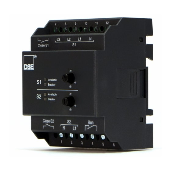
This is not a controlled document. You will not be automatically informed of updates. Any future updates of this document will be included on the DSE website at www.deepseaelectronics.com. The DSE327 is housed within robust plastic case designed for DIN rail mounting. Connections to the module are via screw terminals. -
Page 5: Clarification Of Notation
This document refers to and is referred to by the following DSE publications which can be obtained from the DSE website www.deepseaelectronics.com. 1.3.1 INSTALLATION INSTRUCTIONS DSE Part Description 053-237 DSE327 Installation Instructions 1.3.2 TRAINING DOCUMENTS DSE Part Description 056-022 Switchgear Control 056-091 Equipotential Earth Bonding 1.3.3 THIRD PARTY DOCUMENTS... -
Page 6: Specifications
Specifications 2 SPECIFICATIONS 2.1 PRODUCT VARIANTS CAUTION! Always ensure that the DSE327 ATS is the correct variant for the application. For more information on Product Variants please contact DSE Technical Support; support@deepseaelectronics.com The DSE327 is supplied with varying hardware and configuration parameters depending on the application requirements. -
Page 7: Power Supply Requirements
Specifications 2.4 POWER SUPPLY REQUIREMENTS NOTE: As the power supply is between L1 and N, topologies without a neutral connection are not supported. 2.4.1 230 V VARIANT Description Specification Power Supply Terminals L1 and N from S1 / S2 supplies Nominal Frequency 50 Hz Nominal Voltage... -
Page 8: Voltage And Frequency Sensing
Specifications 2.5 VOLTAGE AND FREQUENCY SENSING NOTE: Frequency failure detection is not supported within this module. However, the module only supports AC supplies in the range of 40 Hz to 70 Hz. NOTE: Voltage phase to phase failure detection is not supported within this module. However, the module supports a maximum phase to phase AC supply of 520 V. -
Page 9: Dimensions And Mounting
Specifications 2.7 DIMENSIONS AND MOUNTING NOTE: In conditions of excessive vibration, mount the panel on suitable anti-vibration mounting Description Specification Mounting Type DIN rail or chassis mounting EN 50022: 35 mm (1.4 “) DIN Rail Width 72 mm X 94.5 mm X 64.5 mm Dimensions Mounted on DIN Rail (2.83 ”... -
Page 10: Applicable Standards
27 – AC Under Voltage Relay 29 – Isolating Contactor 59 – AC Overvoltage Relay In line with our policy of continual development, Deep Sea Electronics Ltd, reserve the right to change specification without notice. 057-286 ISSUE: 3 Page 10 of 24... -
Page 11: Installation
Installation 3 INSTALLATION 3.1 USER CONNECTIONS To aid user connection, terminal descriptions are applied on the front of the module to help identify terminal functions. An example of this is shown below. Close S1 S1 Supply Output Breaker Delay Indicators Timers S2 Supply Close S2... -
Page 12: Connection Descriptions
Installation 3.2 CONNECTION DESCRIPTIONS Cable Name Description Notes Size Close Normally Open Volt-Free 1.0 mm² Used to control the S2 breaker coil. Relay AWG 18 Connect to S2 N. S2 Neutral Voltage 1.0 mm² (Recommend 2 A fuse) monitoring AWG 18 Power supply for module in event of S1 failure. -
Page 13: Typical Wiring Diagram
Installation 3.3 TYPICAL WIRING DIAGRAM As every system has different requirements, these diagrams show only a TYPICAL system and do not intend to show a complete system. Manufacturers and panel builders may use these diagrams as a starting point, however you are referred to the completed system diagram provided by your system manufacturer for complete wiring detail. -
Page 14: Phase, 4 Wire (L1, L2, L3 & N)
Installation 3.3.2 3 PHASE, 4 WIRE (L1, L2, L3 & N) 057-286 ISSUE: 3 Page 14 of 24... -
Page 15: Operation
Operation 4 OPERATION The DSE327 only offers protection for phase to neutral voltage failure and has one mode of automatic operation with two user configurable Breaker Delays for S1 and S2. If the S1 supply is out of limits on any of the phases, the S1 Available LED flashes twice every second for the S1 Transient Delay (5 seconds). -
Page 16: Led Indicators
Operation 4.1 LED INDICATORS 4.1.1 S1 / S2 AVAILABLE LED Two Available LEDs are shown on the module panel. The LEDs indicate if the AC supply is Available. For further information on Protection values refer to section entitled Protection section elsewhere in this manual. -
Page 17: Timers
Operation 4.2 TIMERS Timer Time Range S1 Breaker Delay 1 s to 40 s ±3% S2 Breaker Delay 1 s to 40 s ±3% S1 Transient Delay 5 s ±3% S2 Transient Delay 4 s ±3% Transfer Delay NOTE: For Product Part Number 0327-001-03 the Transfer Delay Timer is fixed at 10 seconds. -
Page 18: Timing Diagram
Operation 4.3 TIMING DIAGRAM The following Timing Diagrams detail the sequence of events during a typical S1 to S2 transfer in various scenarios. In all scenarios, the S1 / S2 Breaker Delays have been configured to 5 seconds. 4.3.1 S1 FAILURE 4.3.1.1 ABOVE POWER SUPPLY LIMIT In this example, the S1 supply voltage has risen above the S1 Breaker Over Voltage Trip or fallen... -
Page 19: S1 Return
Operation 4.3.2 S1 RETURN In this example, the S1 supply voltage has risen above the S1 Breaker Under Voltage Return or fallen below the S1 Breaker Over Voltage Return. Transfer S1 Breaker S2 Cooling Delay Delay complete. S1 Available complete complete Output Switch State... -
Page 20: Protections
Protections 5 PROTECTIONS NOTE: The DSE327 only provides phase to neutral voltage failure detection, frequency failure detection is not supported within this module. NOTE: See section entitled Configuration Mode elsewhere in this document for further details on how to configure the module’s nominal voltage. -
Page 21: Configuration Mode
Configuration Mode 6 CONFIGURATION MODE NOTE: The Configuration Mode feature is only available in modules of hardware version 0327-002-xx and above. For hardware version 0327-001-xx the nominal voltage is fixed to 110 V or 230 V depending upon the module variant. The S1 Breaker Delay Timer is used as a configuration selector when the Configuration Mode is entered. -
Page 22: Selecting The Configuration
Configuration Mode 6.2 SELECTING THE CONFIGURATION In Configuration Mode the module facia LEDs indicate the selected configuration. Upon entering Configuration Mode, the default configuration is always selected due to the S1 Breaker Delay Timer being turned fully anti-clockwise. As the S1 Breaker Delay Timer is rotated clockwise, additional LEDs illuminate to indicate which configuration is selected. -
Page 23: Maintenance, Spares, Repair And Servicing
Maintenance, Spares, Repairs and Servicing 7 MAINTENANCE, SPARES, REPAIR AND SERVICING The DSE327 Series controller is designed to be Fit and Forget. As such, there are no user serviceable parts within the controller. In the case of malfunction, you should contact your original equipment supplier (OEM). - Page 24 This Page is Intentionally Blank...
Need help?
Do you have a question about the DSE327 and is the answer not in the manual?
Questions and answers