Table of Contents
Advertisement
Advertisement
Table of Contents

Related Manuals for UFactory XARM 6


Summary of Contents for UFactory XARM 6
- Page 1 USER MANUA L S H E N Z H E N U F A C T O R Y C O . , LT D . V 1 . 0 . 2...
-
Page 2: Table Of Contents
Thanks for purchasing and using the light-weight multi-DOF(multi-degree-of-freedom) programmable robotic arm developed by UFACTORY As a cost-effective, lightweight, easy-to-use robotic arm, xArm significantly boosts the oper- ational efficiency with automation technology by employing a handful of SDK including python, ROS C++. xArm features custom APP, an user-friendly software xArm Studio which allows users to teach xArm to perform repetitive movement with ‘hand-guide’... -
Page 3: Table Of Contents
Table of Contents Table of Contents Preface Product Formation Additional Information 1. Important Safety Precautions Safety Instructions for Users 1.1. Introduction 1.2. Validity and Responsibility 1.3. Limitations on Liability Exceptions 1.4. Safety Alarms in this Manual 1.5. Safety Precautions 1.5.1. Overview 1.5.2. - Page 4 8.4.1. Digital Output 8.4.1.1. Using Tools for Digital Output 8.4.2. Digital Input 8.4.2.1. Using Tool for Digital Input 8.4.3. Tool Analog Input 8.4.3.1. Using Tool for Analog input, non-differential 8.4.3.2. Using Tool for Analog Input, Differential 8.5. Controller Electrical IO 8.5.1.
- Page 5 9.4.6. Linear Motion 9.4.7. Linear Motion with Circular Arc 9.5. Path Planning Guidelines 10. End-effector 10.1. Gripper 10.1.1. The Flow of Gripper Movement: 10.1.2. Precautions 11. xArm-Python-SDK Library 11.1. Introduction 11.2. Download and Install the Python Library 11.3. Get started 11.4.
-
Page 6: Preface
UFACTORY is devoted to providing reliable and safety information, but these contents do not constitute warranties by UFACTORY. UFACTORY will not have or accept any liability, obli- gation or responsibility whatsoever for any loss, destruction or damage however arising from or in respect of any use or misuse of xArm. -
Page 7: Limitations On Liability Exceptions
1.3. Limitations on Liability Exceptions Any information given in this manual regarding safety must not be construed as a warranty by UFACTORY that the industrial manipulator will not cause injur y or damage even if all safety instructions are complied with. -
Page 8: Safety Precautions
NOTICE:Iif not avoided, could result in personal injury or damage to the equipment. NOTICE CAUTION:If not avoided, could result in personal injury or damage to the equipment. CAUTION 1.5.Safety Precautions 1.5.1.Overview This section contains some general warnings and cautions on installation and application planning for the robotic arm. - Page 9 5.Preliminary testing and inspection for both robotic arm and perimeter protection system before production is essential. 6.The operator must be trained to guarantee a correct operation procedure when using SDK (Python/ROS/C++) and graphical interface xArm Studio. 7.A complete safety assessment must be recorded each time the robotic arm is re-installed and debugged.
- Page 10 The robotic arms authorize restructuring need in accordance with the latest ver- sion of all relevant ser vice manuals. If the robotic arm is modified or altered in any way, UFACTORY (Shenzhen) Technology Co.,Ltd disclaims all liability. 7.Users needs to check the collision and protection measures before transportation.
-
Page 11: Operator Safety
1.Each operator who uses the robotic arm system should be trained through a training course hosted by UFACTORY (Shenzhen) Technology Co., Ltd. Users should fully understand the standardized operating procedures with the robotic arm, and the solution to the robotic arm running error. -
Page 12: Precautions For Transportation
1.When lifting the arm, make sure to hold it steadily, and use the appropriate lifting equip- ment. All regional and national guidelines should be followed. UFACTORY (Shenzhen) Technology Co., Ltd. is not responsible for any damage caused during the transportation of the equip-... -
Page 13: Maintenance And Repair
3.Maintenance and Repair Maintenance must be performed by authorized integrators or UFACTORY (Shenzhen) Tech- nology Co., Ltd. All parts returned to UFACTORY (Shenzhen) Technology Co., Ltd. shall be returned according to the service manual. Make sure to reach the safety requirements of maintenance and repair, follow all regional and national guidelines and test whether all safety functions work normally. - Page 14 DANGER 1.Remove the main input cable from the bottom of the controller to ensure that it is com- pletely powered off. Take the necessary precautions to prevent other people from recharg- ing the system during the repair period. After the power is turned off, the system must be re-examined to ensure that it is powered off.
-
Page 15: Warranties
If there are any defects appear in the device outside the warranty period, UFACTORY (Shen- zhen) Technology Co., Ltd. is not responsible for any damage or loss caused by the equip- ment, such as loss of production or damage to other production equipment. - Page 16 In addition, UFACTORY (Shenzhen) Technology Co., Ltd. is not responsible for any indirect damage and consequences caused by the relevant products.
-
Page 17: The Hardware Composition Of Xarm
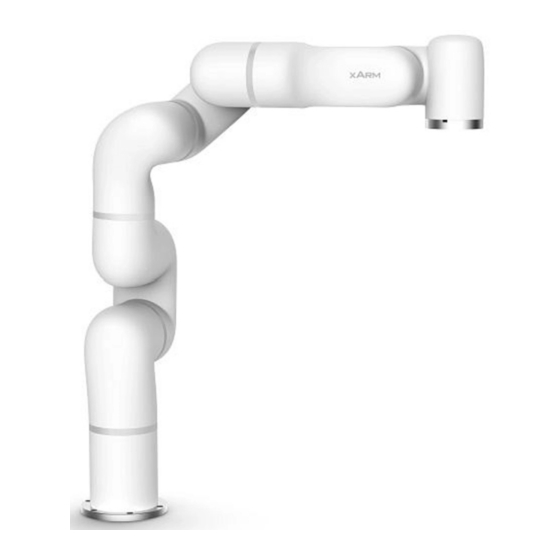
5.The hardware Composition of xArm 5.1.Hardware Composition The composition of robotic arm hardware includes: Robot (Figure 5-1) Controller (Figure 5-2) Robot signal cable (Figure 5-3) Robot power supply cable (Figure 5-4) Controller power supply cable (Figure 5-5) Figure 5.1 Figure 5.2 Figure 5.3 Figure 5.4 Figure 5.5... -
Page 18: Emergency Stop Button
Joint 6 Joint 5 Joint 4 Joint 3 Joint 2 Joint 1 Figure 5.6 Robot Joints 5.2.Emergency Stop Button By pressing the emergency stop button of the controller, a command will be sent to the con- troller for software deceleration to stop all activities of the robotic arm, plus clear all the cache commands in the controller;... -
Page 19: Workspace Of The Robot
ROBOT PWR EMERGENCY STOP CONTROLLER Figure 5.7 Emergency Stop:press the emergency stop button to power off the xArm, and the power light is extinct. Power-on: when the button is rotated in the direction indicated by the arrow, the button is pulled up, the xArm power indicator lights up, and the arm is powered. - Page 20 967mm -700 mm 700mm 700mm Figure 5-8 xArm workspace illustration...
-
Page 21: Robot Installation
6. Robot Installation 6.1.Safety Guidelines for the Robot Environment 01.Make sure the arm is properly and safely installed in place. The mount- ing surface must be shockproof and sturdy. 02.To install the arm body, check that the bolts are tight. 03.The robotic arm should be installed on a sturdy surface that is sufficient to withstand at least 10 times the full torsion of the base joint and at least 5 DANGER... -
Page 22: Robot Installation
6.3. Robot Installation The robotic arm has six M5 bolts and can be mounted through six ∅5.5 holes in the base of the robotic arm. It is recommended to tighten these bolts with a torque of 20N·m. ±0.01 Figure 4.2 Robot Base Mounting ( unit: mm) 6.3.1.Robotic Arm Mounting Configuration The mounting configuration for the robotic arm is designed to inform the controller of the direction of gravity. - Page 23 The initial position of the robotic arm: On the horizontal plane, when user is facing the robotic arm, the initial position is on the left-hand side of the user in a downward direction. Tilt angle: The initial position of the robotic arm and the base of the robotic arm to be mounted should be in a tilt angle, which ranges from 0 to 180°.
-
Page 24: End-Effector Installation
6.4.End-effector Installation End-effector flange has fourteen M16 threaded holes where end-effector of two different sizes can be mounted. The orientation of the end-effector must be documented in a file format, in order to avoid errors and unexpected result when reinstalling the end-effector. The end-effector flange supports the DIN ISO 9409-1-A50/A40 standard. - Page 25 Tool I/O M12-12PIN Figure 6-5 Dimension drawing of tool flange aviation joint (unit: mm) 01.Make sure the tool is properly and safely bolted in place. 02.If the end-effector does not have a locating hole, the orientation of the end-effector must be archived as a file. 03.Make sure that the tool is constructed such that it cannot create a hazardous situation by dropping a part unexpectedly.
-
Page 26: Power Supply For The Robotic Arm
7.Power supply for the Robotic Arm Preparation before Connecting to the Power supply Make sure the power cable and the communication wire is properly connected between the controller and the robotic arm. Make sure the network cable or 485 cable is properly connected. Make sure the power cable for the controller is properly connected. -
Page 27: Shutting Down The Robotic Arm System
7.4. Shutting Down the Robotic Arm System 1.Shutdown the robotic arm in order (1)Cut off the power supply arm Press the emergency stop button to power off the robotic arm, then the power indicator light will be turned off. ROBOT PWR EMERGENCY STOP CONTROLLER... -
Page 28: Robotic Arm Controller
8.Robotic Arm Controller 8.1.Connect the controller to the robotic arm 1.The robotic arm power supply cable connects the power port of the robotic arm and the ROBOT power port of the controller. 2.The robotic arm signal cable is connected to the signal interface of the robotic arm and the ROBOT signal interface of the controller. -
Page 29: Electrical Alarms And Cautions
EMC problems usually occur during the soldering process and are usually prompted by an error message in the log. UFACTORY (Shen- zhen) Technology Co., Ltd. is not responsible for any lose caused by EMC problems. -
Page 30: End-Effector I/O
8.4.End-Effector I/O At the tool side of the robotic arm arm, there is an avionic socket 12-PIN female industrial connector. This connector provides power and control signals for the grippers and sensors used on a particular roboticarm tool. Please refer to the figure below: There are 12 lines inside the cable with different colors, each color represents different functions, please refer to the following table: Line sequence... - Page 31 The electrical specifications are as follows: Parameter Min. value Typical Value Max. Value unit Supply Voltage in 24V Mode Blue +24V (Power) 2000 Supply Current * Note: * It is strongly recommended to use a protection diode for inductive loads. Make sure that the connecting tool and the gripper do not cause any danger when the power is interrupted, for example, the workpiece is dropped from the tool.
- Page 32 8.4.1.1. Using Tools for Digital Output The following example shows how to use the digital output. A s the internal output is an open collector, the resistor should be connected to the power supply according to the load. The size and power of the resistor depends on the specific use. POWER Note: It is highly recommended to use a protection diode for inductive loads as shown below.
- Page 33 8.4.2.1. Using Tool for Digital Input The following figure shows the connection with the simple buttons. POWER 8.4.3.Tool Analog Input The tool analog input is a non-differential input. The electrical specifications are as follows: Parameter Typical Unit Input voltage -0.5 in voltage mode Resolution Input current in...
- Page 34 8.4.3.1.Using Tool for Analog input, non-differential The following figures show how the analog sensor can be connected to a non-differential output. POWER Voltage Mode POWER Current Mode 8.4.3.2. Using Tool for Analog Input, Differential The following figures show how the analog sensor is connected to the differential output. Connect the negative output to GND (0V), then it can work like a non-differential sensor.
- Page 35 8.5. Controller Electrical IO This chapter explains how to connect the device to the electrical I/O outside of the control- ler. This I/O is extremely flexible and can be used in many different devices, including pneu- matic relays, PLCs and emergency stop buttons. The figure below shows the electrical interface layout inside the control box.
- Page 36 The electrical specifications for the internal and external power supplies are as follows. Terminal Parameter Min.value Typical value Max.value Unit Built-in 24V power supply [PWR - GND] Voltage [PWR - GND] Current External 24V input requirement [24V - 0V] Voltage [24V - 0V] Current The digital I/O electrical specifications are as follows.
- Page 37 Precaution: 1. There is no current limit on the digital output of the controller. If the specified data is exceeded, permanent damage may result. 8.5.2.Dedicated security I/O This section describes the dedicated safety inputs and its configuration of the secure I/O. Please follow the universal specifications in Section 5.3.1.
- Page 38 8.5.2.2.Connect To the Emergency Stop button In most applications, one or more additional emergency stop buttons are required. The figure below shows how to connect one or more emergency stop buttons Safety Safety 8.5.2.3.Share emergency stop with other machines When a robotic arm is used with other machines, it requires to set up a common emergency stop circuit in most of the time.
- Page 39 8.5.2.4 Automatically recoverable protective stops The door switch is an example of a basic protective stop device. When the door is open, the robotic arm stops. See the figure below. This configuration is only for applications where the operator is unable to close the door behind it.
- Page 40 8.5.3.Common Digital I/O Function 8.5.3.1.Configurable digital Output The digital output is implemented in the form of NPN. When the digital output is enabled, the corresponding connector will be driven to GND. When the digital output is disabled, the corresponding connector will be open (open/open). Users must follow the electrical specifications set in section 8.5.1 ‘universal specification’...
- Page 41 Configurable Outputs 8.5.3.2.Configurable digital input The digital input is implemented in the form of a weak pull-up resistor. This means that the reading of the floating input is always high. User must follow the electrical specifications set in the 8.5.1 ‘universal specification’. This example shows how a simple button is connected to a digital input.
- Page 42 8.5.4.Universal analog I/O This type of interface can be used to set or measure voltage (0-10V) into and out of other devices. For the highest accuracy, the following instructions are recommended: • Use the GND terminal closest to this I/O. •...
- Page 43 8.5.4.2.Using analog Input The following example shows how to connect an analog sensor. 8.6.Communication Interface The controller provides RS -485 interface and Ethernet interface, as shown in the figure below. CONTROLLER RS-485 ROBOT 24V PWR ROBOT TEACH POWER 8.6.1.RS-485 Communication The controller provides an RS-485 interface.
- Page 44 8.6.1.1. RS-485 Circuit Order Serial number Description 485_A 485_B connect connect connect connect connect 8.6.2.Ethernet TCP/IP The control box provides a gigabit Ethernet interface. ROBOT PWR CONTROLLER EMERGENCY RS-485 STOP ROBOT ROBOT 24V PWR CONTROLLER TEACH POWER Ethernet connection steps:The controller and the computer are connected via Ethernet. One end of the network cable is connected to the network interface of the controller, and the other end is connected to the computer or LAN network interface.
- Page 45 8.7. Controller Command Caching Mechanism The current controller can cache 512 commands. If more than 512 commands need to be sent, the controller will execute the current commands before sending further commands. When awaiting commands of the controller exceed the maximum buffer amount (512), and continues to send the commands, a return warning will be shown.
- Page 46 9.The motion mode of the robot The robotic arm arm has four underlying motion modes: joint motion, linear motion, linear circular motion, and servoj motion. The robotic arm moves from point A to point B and then to point C, the four basic motion modes have different joint rotation processes. The following motion modes are in position mode: Joint Motion: to achieve the point-to-point motion of joint space ( unit: degree/radian), the speed between each command is discontinuous.
- Page 47 Figure 6.1 shows the zero pose of the robotic arm, and the rotation angle of each joint is 0. When the x/y/z/Roll/Pitch/Yaw value of the TCP offset setting is 0, the robotic arm zero point Cartesian value would be: x/y/z/Roll/Pitch/Yaw = [206mm, 0,112mm , 180°, 0, 0] 112mm 206mm If the end-effector is installed in the robotic arm, make sure to...
- Page 48 9.3.Joint Motion The robotic arm consists of joint modules. The position of the end-effector is controlled by coordinating the rotation angle of each joint. The joint motion reach the target point with the fastest path, the end trajector y is not a straight line, and the speed unit is °...
- Page 49 Joint Joint(unit: rad) Joint(unit: degree) ±2PI ±360 -2.18~2.18 ±125 -4.0100 ~ 0.1000 -300 ~ 6 ±2PI ±360 -100~ 180 -1.7500 ~ PI ±2PI ±360 9.3.3. Joint Operating Speed Joint Speed: refers to the rotating degree per second, the range is 1°/s ~ 180°/s. When the robotic arm is in operation, the maximum speed will be influenced by the payload, speed and the pose, and the maximum speed would not be an absolute value.
- Page 50 1.After the release of the joint brake and manually dragging the arm, please always pay attention to the degree of joint rotation to avoid exceeding the rotation range of the robot joint and damage the inter- nal structure of the robotic arm. 2.After all the joints are closed, the robot arm can be driven.
- Page 51 9.4.2. TCP Setting TCP offset: When the x/y/z/Roll/Pitch/Yaw value of the TCP offset setting is 0, TCP coincides with the centre point of the tool output flange. TCP load and center of gravity: Please set the payload and tool center of gravity offset according to the actual situation of the arm.
- Page 52 The ±180 ° points of the Roll/Pitch/Yaw are coinciding in the space, and the range is ±180°, so it is possible to have ±180° when the robotic arm is reporting the position. RPY [rad] Roll angle, pitch angle, and yaw angle (RPY). The RPY rotation matrix (X, Y', Z" rotation) is determined by the following formula: R rpy ( γ, β,α...
- Page 53 1.In the case where the length of the end tool is more than the end joint of the robotic arm, the direction of rotation must be clear when setting the degree of rotation. 2.You must check the TCP offset before recording the Cartesian position.DAN- CAUTION 9.4.4.TCP Position Range To approach the limit value, the joint attitude needs to be adjusted.
- Page 54 9.4.7.Linear Motion with Circular Arc Figure 6.7 ●In terms of speed, the speed between arc motion commands is continuous. ●In terms of track accuracy, it will reach point C from the current point A, but will not reach point B in the middle, and will bypass the circular path around point B. ●The arc blending radius is reflected in each command with an arc line, and an arc is made at the middle point.
- Page 55 01.Approach the joint speed, joint range, TCP speed, and the TCP position range may cause an error reporting mechanism. 02.Exceeding the specified joint speed, joint range, TCP speed, and TCP posi- tion will trigger an error reporting mechanism. WARNING 10.End-effector 10.1.Gripper The gripper is a robotic arm end-effector that can dynamically pick up objects.
- Page 56 The gripper of the robotic arm in the zero position will exceed the mounting surface.
- Page 57 11.xArm-Python-SDK Library 11.1.Introduction The xArm-Python-SDK is an integrated librar y for controlling a series of motion planning that is based on controller communication protocol package, and the SDK is for advanced users. When controlling the real machine, make sure the robotic arm will not touch any obstacle.
- Page 58 11.5.Initialize the robotic arm motion mode Please check below for the Python code and click on the link for more Example s: https://github.com/xArm-Developer/xArm-Python-SDK/tree/dev/ Example /wrapper Note: Initialize the robotic arm 1.Import the XArmAPI interface import os import sys sys.path.append(os.path.join(os.path.dirname(__file__), '../..')) from xarm.wrapper import XArmAPI Note:...
- Page 59 Note: # 6. Set the position of the xArm robotic arm # angle=[20, 0, 0, 0, 0, 0, 0] indicates that joint 1 of the robotic arms is rotated by 20 ° , and the remaining joints are not rotated. # speed = 30 indicates that the joint rotation speed is 30°/s # is_radian = False means the unit is not the radian (rad), but the degree (°) # wait = True means waiting for the robotic arm to complete the command...
- Page 60 12.ROS Library 12.1.Introduction This code librar y contains sample development kit for xArm model files and related con- trols, plans, etc. The environment for development and testing is Ubuntu 16.04 + ROS Kinet- ic Kame. New function support, sample code, bug fixes, etc. will be updated, and the tutori- al is based on the online version.
- Page 61 Appendix 1.Technical Specifications xArm 1,4,6 ±360 ±125° Joint Range -230°~6 -100°~180° ±700mm ±700mm Cartesian Range -400mm~951.5mm Roll/Yaw/Pitch ±180° Maximum 180°/s joint speed Payload Reach 700mm Degrees of Freedom Repeatability ±0.1mm Max Speed of 1m/s End-effector Controller Size 260mm*180mm*120mm(L*W*H) Weight 10.5kg (no controller) *Ambient 0-50 °C*...
- Page 62 ISO Class Cleanroom Robot Mounting 8 digital inputs, 8 digital outputs, Controller 2 analog inputs, 2 analog outputs, I/O interface End-effector 2 digital inputs, 2 digital outputs, I/O interface 2 analog inputs, RS485 Programming Python/C++/ROS underlying interface Robotic Arm Self-defined Communication Protocol Controller TCP-IP/modbus RTU...
- Page 63 Suction Cup Payload Suction Cups Maximum Vacuum Degree -90kpa Notes: *1. All joints of xArm 6 use harmonic gear drive. *2. The ambient temperature of xArm is 0-50 °C, and reduces when the joint continued for high-speed operation.
- Page 64 2.Robot Movement & Status Analysis There are four types of controller motion mode: 0:Position Control mode ( joint motion, linear motion, circular, linear motion) 1:Servo motion mode (servo motion) 2:Joint teaching mode (not available) 3:Cartesian teaching mode (not available) There are three types of controller status setting: 3:Suspend the current movement 4:Stop all the current movements (including command buffer, restart the system) 0:Start the movement...
- Page 65 3.Controller Communication Protocol Protocol Format 3.1. 【The Meaning of symbols】 【u8】 :1 byte, 8-bit unsigned int 【u16】 :2 bytes, 16-bit unsigned int 【fp32】 :4 bytes, float 【str】 :String 【System Reset 】: After using this command, the command cache will be cleared, and the robotic arm movement will stop.
- Page 66 3.3. 【MODBUS-TCP Communication Format】 Parameters Default TCP Port:502 protocol: 0x00 0x02 Control (Only this one for now) Request instruction format Parameters Transaction Protocol Length Register (refer to the statement Identifier Format (u16) (u16) (u8) of each instruction) (u16) 2 byte 2 byte 2 byte 1 byte...
- Page 67 REPORT_TCP_NORMAL REPORT_TCP_NORMALDefault port:30001 Frequency:5Hz Byte Order Content: 1~87 bytes:Same as 【 REPORT_TCP_DEVELOP】 88 byte:ser vo brake status (u8 bit0 ~ bit7correspond to 1~6 joints respectively, 0 not enabled, 1 enabled) 89 byte:ser vo brake status (u8 bit0 ~ bit7correspond to 1~6 joints respectively, 0 not enabled, 1 enabled) 90 byte:Error code (u8) 91 byte:Warning code (u8)
- Page 68 Register: 11(0x0B) ⸺ Enable/Disable servo(System reset) Reply parameters none Example Enable all servos: 00 01 00 02 00 03 0b 09 01 (MODBUS-TCP) Disable all servos: 00 01 00 02 00 03 0b 09 00 xArm-Python-SDK motion_enable() interface Register: 12(0x0C) ⸺ Motion Status Setting Length:...
- Page 69 Register: 14 (0x0E)⸺ Acquire the number of commands in the command buffer none Required parameters Length: 2 bytes Reply parameters parameter1(u16) : The number of instructions in the instruction buffer Example 1 00 01 00 02 00 01 0e (MODBUS-TCP) xArm-Python-SDK get_cmdnum() interface...
- Page 70 Register: 18 (0x12)⸺ Setting the brake Switches Separately(System reset) Length: 2 bytes parameter 1(u8): Control the brakes 1~6: Select a motor joint separately Required parameters 8 : acts on all joints parameter 2(u8): operation 1: enable the servo 0: release the brake none Reply parameters enable the servo:...
- Page 71 Register: 21 (0x15) ⸺ Cartesian linear motion Length: 2 bytes Reply parameters parameter1(u16) : the number of commands in the instruction buffer xArm-Python-SDK set_position() interface Register: 22 (0x16) ⸺ Linear motion with circular arc Length: 40 bytes parameter1(fp32*6):Cartesian coordinates[X Y Z A B C], unit :...
- Page 72 Register: 23 (0x17) ⸺ P2P Joint Motion Example : 00 01 00 02 00 29 17 00 00 00 00 00 00 00 00 00 00 00 00 00 00 00 00 00 00 0000 00 00 00 00 00 00 00 00 c2 b8 32 3e c2 b8 32 3e 00 00 00 00 Example 1 (Note: Set the joint position to [0 0 0 0 0 0 0] speed is...
- Page 73 Register: 29 (0x1D)⸺ Servoj Motion Length: 40 bytes parameter1(fp32*7): correspond to axis 1~6 respectively, unit: rad Required parameters parameter2(fp32): motion speed (no meaning for now,0) parameter3(fp32): acceleration (no meaning for now,0) parameter4(fp32): motion time (no meaning for now,0) Reply parameters none xArm-Python-SDK set_servo_angle_j()
- Page 74 Register: 33 (0x21)⸺ Set joint space jerk Length: 4 bytes Required parameters parameter1(fp32): jerk, unit: radians/s^3 Length: 2 bytes Reply parameters parameter1(u16):number of commands in the command buffer xArm-Python-SDK set_joint_jerk() interface Register: 34 (0x22)⸺Set joint space max acceleration Length: 4 bytes Required parameters parameter1(fp32):...
- Page 75 Register: 36 (0x24)⸺End load setting(System reset) none Reply parameters xArm-Python-SDK set_tcp_load() interface Register: 37(0x25)⸺Set collision detection sensitivity(System reset) Length: 1 byte Required parameters parameter1(u8): detect sensitivity none Reply parameters xArm-Python-SDK set_collision_sensitivity() interface Register: 38(0x26)⸺Set hand-guiding sensitivity for teaching mode(System reset) Length:...
- Page 76 Register: 40 (0x28)⸺Save the current system configuration parameters none Required parameters none Reply parameters xArm-Python- save_conf() SDK interface 41~50 Acquire Motion Information Register: 41 (0x29)⸺Acquire the current Cartesian position of the controller Required parameters none Length: 24 bytes Reply parameters parameter1(fp32*6): Cartesian coordinates, unit: mm, rad xArm-Python- get_position()
- Page 77 Register: 45 (0x2D)⸺Check the limit of the joint space Length: 28 bytes Required parameters parameter1(fp32*7): the angle of 1~6 joints, unit: rad Length: 1 byte parameter1(u8): search result Reply parameters 1 : collision occurs 0 : no collision xArm-Python-SDK is_joint_limit() interface Register:...
- Page 78 Register: 106 (0x6A)⸺Acquire the status of the current robotic arm servo Required parameters none Length: 17 bytes parameter1(u8): Instruction execution state 0: Normal 1: The server has an error message 3 : Communication fail parameter2(u8*2): Joint1 [servo status + servo error code] parameter3(u8*2):...
- Page 79 Register: 117 (0x75)⸺Set the gripper mode Length : 1 byte parameter1(u8) Required parameters 1 : position mode 2 : speed mode (not yet open) 3 : moment mode (not yet open) none Reply parameters xArm-Python- set_gripper_mode() SDK interface Register: 118 (0x76)⸺Set the zero point of the gripper none Required parameters none...
- Page 80 Register: 120 (0x78)⸺Set the gripper position speed none Reply parameters xArm-Python-SDK i set_gripper_position() nterface Register: 121 (0x79)⸺Set the gripper position speed Length: 4 bytes Required parameters parameter1(fp32): the position value of the gripper, unit: pulse none Reply parameters xArm-Python-SDK set_gripper_speed() interface Register:...
- Page 81 3.3. 【MODBUS-TCP Communication Format】 Register: 131 (0x83) - Get configurable digital gpio input none Send parameter Length: 2 bytes Response parameter Parameter 1(u16): gpio signal, bit0 ~ bit5 correspond to signals of gpio0~gpio5 xArm-Python-SDK get_cgpio_digital() interface Register: 132 (0x84)⸺Obtain analog input AIN1 none Send parameter Length:...
- Page 82 Register: 135 (0x87)⸺Set the analog outputAIO1 Length: 2 bytes Send parameter parameter1(u16): analog output1,Range 0~4096,Corre- sponding to 0~10V Response parameter none xArm-Python-SDK get_cgpio_digital() interface Register: 136 (0x88)⸺Set the analog output AIO2 Length: 2 bytes Send parameter parameter1(u16): analog output2,Range 0~4096,Corre- sponding to 0~10V Response parameter none...
- Page 83 Register: 139 (0x8B)⸺Obtain GPIO status Send parameter none Length: 34 bytes parameter1(u8): gpio Module status 0 normal 3 Gripper has error message 6 Communication failure parameter2(u8): gpio module error code 0: normal Not 0: Error code parameter3(u16): Digital input function io status parameter4(u16):...
- Page 84 4.Joints Alarm Message and General Response Users can power off and on the system as an alarm response, the steps are as follows (re-powering needs to go through all the following steps): 1.Re-powering the robotic arm via the emergency stop button on the controller. 2.
- Page 85 Alarm Code Alarm Code Alarm descriptiont Alarm response 0x13 Abnormal current detection Power on again 0x14 Joint overcurrent Check if the brake is normally open Joint speeding Reduce the moving speed 0x15 Check if the location setting 0x16 Position command is too large value is too large Check if it caused by overtime 0x17...
- Page 86 Alarm Code Alarm Code Alarm descriptiont Alarm response 0x28 Joint undervoltage Reduce the acceleration EEPROM read and write 0x31 Power on again error Power on again Motor angle initialization 0x34 failed For alarm codes that are not listed in the above table: Power on again. If the problem remains unsolved after power on/off...
- Page 87 5.Controller Alarm Message and General Response 5.1 Controller Alarm Message Code If there is an error in the hardware of the robotic arm/the software of the controller/ in sending command, an error or warning will be issued. This error/warning signal will be fed back when the user sends any command;...
- Page 88 Error code Description Alarm Response Teaching mode current Check for collisions, load settings, 31 (0x1F) abnormality and collision sensitivity and speed. Three-point arc command Please re-plan the path. 32 (0x20) calculation error Controller gpio module 33 (0x21) error 5.2 Controller Alarm Code Alarm does not affect the normal operation of the robotic arm, but it may affect the user's program operation.
- Page 89 Alarm code Alarm description Alarm Response Abnormal current Power on the robotic arm again 0x09 detection and enable the gripper 0x0B Gripper overcurrent Re-enable the gripper. 0x0C Gripper speeding Power on again and enable the gripper Please check if the location Position command is 0x0E setting value is too large...
- Page 90 w ww. ufa ctor y.cc Website: Em a i l: i nfo @u facto r y.cc A ddress:2 F, B uilding M-6, Ma Qu e Li ng In d u st ri al Zo n e , Nansha n District , Shenz h en , G u a ngdo n g, P.R . C h i n a...
Need help?
Do you have a question about the XARM 6 and is the answer not in the manual?
Questions and answers