Table of Contents
Advertisement
Quick Links
Advertisement
Table of Contents

Related Manuals for Belden Grass Valley NV9606


Summary of Contents for Belden Grass Valley NV9606
- Page 1 NV9606 NV9000 Control Panel User’s Guide UG0044-01 14 Nov 2014...
- Page 2 Copyright & Trademark Notice Copyright © 2014 Grass Valley. All rights reserved. Belden, Belden Sending All The Right Signals, and the Belden logo are trademarks or registered trademarks of Belden Inc. or its affiliated companies in the United States and other jurisdictions.
- Page 3 NV9606 User’s Guide Change History Rev. Date Description Approved 05 Nov 10 17286 Initial release. D. Cox 14 Nov 14 19357 Reformatted. D.Cox Safety Compliance FCC Statement This equipment has been tested and found to comply with the limits for a Class A digital device, pursuant to part 15 of the FCC Rules.
- Page 4 Restriction on Hazardous Substances (RoHs) Grass Valley is in compliance with EU Directive RoHS 2002/95/EC governing the restricted use of certain hazardous substances and materials in products and in our manufacturing processes. Grass Valley has a substantial program in place for RoHS compliance that includes significant investment in our manufacturing process, and a migration of Grass Valley product electronic components and structural materials to RoHS compliance.
- Page 5 NV9606 User’s Guide General Warnings A warning indicates a possible hazard to personnel which may cause injury or death. Observe the following general warnings when using or working on this equipment: • Heed all warnings on the unit and in the operating instructions. •...
-
Page 7: Table Of Contents
Table of Contents 1 Preface ..........1 Chapter Structure . - Page 8 Table of Contents Secondary Modes ............... . . 27 Button Legends .
- Page 9 NV9640A User’s Guide 7 Technical Details ........45 Power Specifications .
- Page 10 Table of Contents...
-
Page 11: Preface
Preface Chapter 1 is an introduction to the NV9606 User’s Guide. Topics Chapter Structure ............... . . 1 The PDF Document . -
Page 12: Terms, Conventions And Abbreviations
Preface Terms, Conventions and Abbreviations Use the ‘First Page’ , ‘Previous Page’ , and ‘Next Page’ , and ‘Last Page’ buttons to go to the first, previous, next, or last page within a PDF file. Note To display the navigation buttons, right-click the Tool Bar area, and check ‘Navigation’ . •... -
Page 13: Introduction
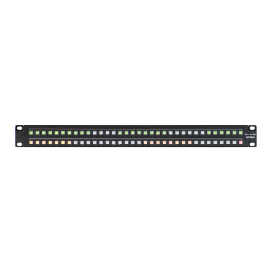
Introduction The NV9606 is a 1RU control panel. It has 68 backlit function buttons: Function Buttons Function Buttons The NV9606 can operate either by itself as a stand-alone panel or as a extension of an NV9607 control panel. When the panel is stand-alone, the function buttons are limited: an operator can select sources and destinations or execute salvos. -
Page 14: Tally Interface
Introduction Tally Interface At the rear of the panel is a DB25 connector that provides 8 tally inputs and 4 tally outputs. (The outputs are solid state relay outputs.) Both inputs and outputs are optically isolated. During configuration, you can construct Boolean logic that switches the outputs on or off. The terms of the logic expressions are states of the source and destination devices, etc., controlled by the NV9000 control system. -
Page 15: Multi-Destination Mode
NV9606 User’s Guide Single-Destination Mode with Breakaway In this mode too, the single destination is configured as the default destination. There are no destination buttons. Pressing a source button completes a take unless the corresponding NV9607 has a ‘Source Preview’ button and it is active (high-tally). Breakaway is possible in this mode if the panel has level buttons. - Page 16 Introduction Other NV9606 Functions...
-
Page 17: Installation
Installation Chapter 3 provides installation and connection instructions. Topics Package Contents ............... . . 7 Installation . -
Page 18: Installing Software And Documentation
Installation Installing Software and Documentation (Then NV960 has several options for a serial card and breakout box for such a connection.) Refer to the NV9000-SE Utilities User’s Guide for serial configuration options. Contact Miranda regarding serial interface options. 2 Connect one or both power supplies. First connect the 4-pin connector to PS1 or PS2 on the rear of the router. -
Page 19: Setting The Panel Id
NV9606 User’s Guide You can now prepare an NV9606 configuration in NV9000-SE Utilities and upload the configura- tion to the NV9606. You need a panel ID to create a NV9606 configuration. When you upload the configuration, the panel ID you entered in NV9000-SE Utilities designates the actual panel to which the upload will occur. -
Page 20: Testing
Installation Testing 5 Right-click that list entry. You will get a ‘Change ID’ message allowing you to change the panel ID: 6 Click ‘Change ID’ . A window appears in which you can enter a new panel ID: 7 Change the panel ID to a suitable value. Make a note of the value. 8 Now click ‘Configuration’... - Page 21 NV9606 User’s Guide 1 Do the buttons illuminate? When an NV9606 powers up, one or more of its buttons are sup- posed to turn green or amber. Did it pass the panel test mentioned above? 2 When the NV9606 powers up and it is connected to the system controller, it should initialize completely.
- Page 22 Installation Testing...
-
Page 23: Configuration
Configuration Chapter 4 provides configuration instructions for the NV9606. Topics Summary ................13 Adding a Panel to an NV9000 Configuration . - Page 24 Configuration Adding a Panel to an NV9000 Configuration After launching NV9000-SE Utilities, choose ‘Control Panels’ from the Configuration pane in the navigation area. The ‘Control Panels’ configuration page appears: Click ‘Add Control Panel’ at the bottom of the configuration page. The ‘Add Control Panel’ page appears: Choose “NV9606”...
- Page 25 NV9606 User’s Guide In the first and third cases, you will create a new configuration file whose name you designate. .606 The file extension for an NV9606 configuration file is . Click ‘Next’ or ‘Finish’ to proceed. Click ‘Previous’ to go back the previous page. Click ‘Cancel’ to terminate the entry operation. ...
-
Page 26: Nv9606 Panel Configuration Page
Configuration NV9606 Panel Configuration Page NV9606 Panel Configuration Page This is the default NV9606 panel configuration page in NV9000-SE Utilities: Panel Image Button Definition Section GPIO Sec- tion Panel Fig. 4-1: NV9606 Configuration Page (Default) After you configure buttons, the appearance of the panel buttons will have changed. The panel buttons on this page will show legends, determined from the button type assigned to the button. -
Page 27: Configuration Tasks
NV9606 User’s Guide • Panel options. In this section, configurers may specify the behavioral characteristics of the panel. See Panel Options, following. Configuration Tasks The person configuring an NV9606 panel will want to consider how best to use the buttons to support the devices and routers in the router control system at hand. -
Page 28: Button Definitions
Configuration Button Definitions Status Monitor None The current source video is not sent to a monitor. ‹device› The current source video for the selected destination appears on the specified monitor (device). High-Tally Illumi- (The default is Sets the panel’s button illumination for high-tally. Use the arrow nation 100.) buttons to scroll to a value. -
Page 29: Button Specification
NV9606 User’s Guide Button Specification The button definition section configures the button you have selected in the image of the NV9606: When you choose a button type, additional drop-down menus can appear, depending on the button type, allowing you to further specify the button’s behavior. Available options and selec- tions vary from button type to button type. - Page 30 Configuration Button Definitions Type Modes Description Default state S, B, X The button returns the panel to its most recent power-up state. That is called the default state. The button definition has no fields to configure. Destination X, L The button selects a destination. The destination name appears in the ‘Destination’...
- Page 31 NV9606 User’s Guide Type Modes Description Hold B, X In single-destination mode with breakaway, this button retains break- away levels after a take. In limited X-Y mode, this button allows the operator to perform a gang (or “dub”) route. In hold mode, destination selections are cumulative, and not mutually exclusive.
- Page 32 Configuration Button Definitions Type Modes Description Page Down The button scrolls the display down one page (either 3 lines or 7 lines according to the panel’s display configuration). The button definition has no fields to configure. Page Up The button scrolls the display up one page (either 3 lines or 7 lines according to the panel’s display configuration).
- Page 33 NV9606 User’s Guide Type Modes Description Source All, L The button selects a source. The source name appears in the ‘Status’ display. Pressing a source button completes a take unless source preview mode is in effect. In that case, pressing a take button is required for the completion of the take.
- Page 34 Configuration Button Definitions Type Modes Description Source Shift The button toggles between the first and second source sets. The button definition has no fields to configure. The button affects the operation of any source button (in any mode). Source buttons represent two sources. One belongs to one source set and the other belongs to the other source set.
-
Page 35: Operation
Operation Chapter 5 provides operating instructions for the NV9606 control panel. Topics Summary ................25 Operating Concepts . -
Page 36: Limited X-Y Mode
Operation Summary Limited X-Y Mode In limited X-Y mode, takes occur from a single source to a single destination. Destinations are selectable and there are two pages of destinations in addition to the two pages of sources. Breakaway is possible if the panel has level buttons. Pressing a source button completes a take unless source preview mode is active (when the panel is an NV9607 extension). -
Page 37: Secondary Modes
NV9606 User’s Guide Secondary Modes As a stand-alone panel, the NV9606 has no secondary modes. When it is an NV9607 extension, the secondary modes are: • Source preview mode — exists (in any operating mode) when you press a ‘Source Preview’ button. -
Page 38: Destination Shift
Operation Operating Concepts Destination Shift Destination shift applies only in ‘Limited X-Y’ mode. Each destination button can represent two destinations. A ‘Destination Shift’ button selects which of the two destinations the destination button will select. A destination shift button is a toggle that enables either the first or second destination of desti- nation buttons. -
Page 39: Limited X-Y
NV9606 User’s Guide Limited X-Y In limited X-Y mode, this button allows you to perform a gang (or “dub”) switch. In hold mode, destination selections are cumulative, and not mutually exclusive. Follow these steps to route a source to more than one destination: 1 Select the first destination to which you want to route the source. -
Page 40: Buttons
Operation Operating Concepts Buttons As a stand-alone panel, the NV9606 has 5 button types: Destination Previous Source Salvo Source Panel Lock As an NV9607, the NV9606 has 21 button types, not including “undefined” which is not an actual button type: Broadcast Free Source Page Up... -
Page 41: Default State
NV9606 User’s Guide Default State S, B, X The ‘Default State’ button returns the panel to its most recent power-up state. That is called the default state. (It does not cause any changes to the routers, control system, or its signals.) Destination L, X The button selects a destination. -
Page 42: Destination Shift
Operation Operating Concepts Protects apply to selected levels in single-destination mode with breakaway. The NV9606 provides no explicit indication, during operation, whether a destination is locked or unlocked. Destination Shift The ‘Destination Shift’ button toggles between the first and second destination sets (which are available only in limited X-Y mode). -
Page 43: Name Set Toggle
NV9606 User’s Guide Without the button, the operator has no access to the menu functions. By pressing certain buttons, you makes menu selections and enter data (such as panel ID) or change brightness values. When the panel is in menu mode, you must press the ‘Menu’ button to cycle through the functions of the menu. -
Page 44: Source Is Master
Operation Operating Concepts The nature of source buttons differs according to the NV9607 panel’s configured operating mode: • Single-destination, single-destination with breakaway, and limited X-Y modes A source button can select one of two sources. The first source belongs to source “page” 1 and the second source belongs to source “page”... -
Page 45: Lock, Protect, And Release
NV9606 User’s Guide Lock, Protect, and Release In a multi-user system, routes made by one user can be made safe from being accidentally or maliciously change by another user. Definitions Owner The user ID of a panel where a lock or protect was issued. Source lock No one can use the source. -
Page 46: Takes
Operation Operating Concepts Takes Pressing a source button completes a take, in any mode, unless source preview mode is active. In that case, it is necessary to press a ‘Take’ button to complete the take. The NV9606 can operate by itself as a stand-alone panel or as an extension to an NV9607. As an extension to an NV9607, it operates according to the mode in which the NV9607 is configured. -
Page 47: Case 5 - Nv9607 Extension, Limited X-Y Mode
NV9606 User’s Guide and the take button turns red. If that is the correct source, press a ‘Take’ button. If it is not the correct source, you can press another source and then press a ‘Take’ button. A take is all-level when all the level buttons are selected (high-tally) or when none of the level buttons are selected. -
Page 48: Self-Test
Operation Self-Test Self-Test You can perform a short test of the NV9606 when it is disconnected from its network and powered up. The panel powers up with the top right button illuminated in green and a moving pattern of green button illumination on the top row of the panel: Self- test Here we call the button at the top right the “self-test”... -
Page 49: Gpio
GPIO Chapter 6 provides information about the tally (GPIO) interface. Topics The Interface ................39 GPIO Configuration Concepts . -
Page 50: Output
GPIO GPIO Configuration Concepts During contact closure, a current of 1.2mA flows. A maximum of 48VDC can be applied to the tally input for less than 5 seconds without failure. No voltage above 5VDC should be continu- ously applied. Output A tally output is a solid state relay (no audible click) with a maximum resistance of 10W and current capability of 150mA. -
Page 51: Configuring Outputs
NV9606 User’s Guide Configuring Outputs Clicking an output button (one of 4) displays a “Relay Rule” dialog for the output: term term term operator operator Fig. 6-4: Relay Rule Dialog In this dialog, you create a Boolean expression involving sources destinations, port status, and GPI (input) status. - Page 52 GPIO Configuring Outputs (To allow a relay to switch when an input transitions from on to off, precede the input term by “NOT. ” For example, the expression INPUT 3 OR NOT INPUT 8 will evaluate TRUE when either input 3 goes on or input 8 goes off.) You can also include one or more sub-expressions regarding the state of output ports.
-
Page 53: Configuring Inputs
NV9606 User’s Guide Configuring Inputs Clicking an input button (one of 8) displays the GPI input dialog: An event is signalled when a transition occurs on the input from on to off or from off to on. You can configure the NV9606 to recognize either occurrence on any of the 8 inputs, and specify one of 4 behaviors for each event or both: 1 Execute a salvo. - Page 54 GPIO Configuring Inputs...
-
Page 55: Technical Details
Technical Details Chapter 7 provides electrical and mechanical specifications for the NV9606. Topics Power Specifications ..............45 NV9606 Specifications . -
Page 56: Nv9606 Specifications
Technical Details NV9606 Specifications 2.39 [60.7] 5.24 [133.0] Indicator LED 1.62 [41.0] AC Input DC Output Fig. 7-1: The power output has Molex 4-pin plug. See Power Cord Retention on page 50. NV9606 Specifications NV9606 Physical Specifications Specification Detail Dimensions Height: 1.72 in (43.7.9 mm), fits EIA 1 RU (1.75 in or 44.5 mm), Width: 19.0 in (482.6 mm). -
Page 57: Environmental Specifications
NV9606 User’s Guide Environmental Specifications NV9606 Environmental Specifications Specification Detail Operating temperature 0–30 °C, ambient. Relative humidity 0 to 90%, non-condensing. Cooling No fan required. Defaults Initial Panel State Destination: the configured default. Buttons: low-tally is 40% brightness by default and stays at its most recent setting. Configuration Page The initial NV9606 configuration has no buttons defined. - Page 58 Technical Details Drawings Fig. 7-2: Front, Top, and Rear View of the NV9606...
-
Page 59: Misc. Topics
Misc. Topics Chapter 8 provides the following. Topics Power Cord Retention ..............50... -
Page 60: Power Cord Retention
Misc. Topics Power Cord Retention Power Cord Retention Use the supplied retention strap to keep the AC power cord firmly connected to the power supply. Follow these steps to use the strap: 1 Firmly insert the AC power cord into the power supply. Examine the last figure in this section to see how the strap should be applied. -
Page 61: Glossary
Glossary AES/EBU (Audio Engineering Society/European Broadcasting Union). AES and EBU are standards organizations. Breakaway A condition where a destination has multiple sources on different levels. Category A category represents a set of devices. (The concept of categories exists to make it easier to select devices at a control panel.) A category can contain sources, destinations, or devices that are both sources and destinations. - Page 62 Glossary or more input ports. A destination is a device that is connected to one or more output ports. An example of such a device would be a monitor. A device can be both a source and destination. An example of such a device is a VTR. System The system administrator is the person responsible for installing, configuring, and maintaining a administrator...
-
Page 63: Index
Index page down ........22, 33 page up ........22, 33 panel lock . - Page 64 Index Configuration ........2 Devices NV9606 .
- Page 65 NV9640A User’s Guide Glossary ..........51 Keycaps .
- Page 66 Index single-destination, with breakaway 5, 13, 19, 23, 25–26, panel ..........17 28, .
- Page 67 NV9640A User’s Guide destination ........35 Source shift (button) .
- Page 68 Index WC0053 ..........4 Web site .
-
Page 69: Contact Us
Contact Us Grass Valley Technical Support For technical assistance, please contact the Grass Valley Technical Support center nearest you: Americas Asia Office hours: 9:00 a.m. – 9:00 p.m. (EST) Office hours: 9:00 a.m. – 6:00 p.m. (GMT+8) Telephone: +1-800-224-7882 Telephone: +852 2539 6987 Fax: +1-514-335-1614...
Need help?
Do you have a question about the Grass Valley NV9606 and is the answer not in the manual?
Questions and answers