Advertisement
1. DESCRIPTION
Designed for cooling or heating application. MT-512
temperature sensor, 1 digital input, data logger, cyclic time for natural defrost, IP65 frontal, min-max
temperature record, sensor response time control, fast freezing mode, tamper-proof function, control
functions shutdown and RS485 serial communication port for Sitrad real-time monitoring and
management.
Product conforming to UL Inc. (United States and Canada).
2. SAFETY RECOMMENDATIONS
- Check the controller for correct assembling;
- Make sure that the power supply is off and that it is not turned on during the controller installation;
- Read the present manual before installing and using the controller;
- Use adequate Personal Protective Equipmenet (PPE);
- For application at sites subject to water spills, such as refrigerated cabinets, install the protecting vinyl
supplied with the controller;
- For protection under more critical conditions, we recommend the Ecase cover, which we make
available as an optional item (sold separately);
- The installation procedures should be performed by a qualified technician.
3. APPLICATIONS
• Refrigerated displays
• Walk-in coolers
• Hot cabinets
• Greenhouses
4. TECHNICAL SPECIFICATIONS
MT-512E Log 115 or 230 Vac ±10%(*) (50/60 Hz)
Power supply
MT-512EL Log 12 or 24 Vac/dc +10%(*)
Control temperature
-50 to 105ºC (-58 to 221°F)(**)
Operating temperature
0 to 50 ºC / 32 to 122°F
NO -16A / 2HP
Maximum output current
NC - 500W / 1/10HP
Maximum consumption of device
1.5 VA
Operating humidity
10 to 90% RH (without condensation)
Dimensions (mm)
76 x 34 x 77 mm (WxHxD)
Cutout dimensions (mm)
71 ± 0,5 x 29 ± 0,5 mm (see image V)
(*)
Admissible variation in relation to the voltage rating.
(**)
This device can measure and control temperatures of up to 200° C when used in conjunction with a model SB59 silicon
sensor cable (sold separately).
Note: Sensor cable length can be increased to up to 200 meters by the user by using a PP 2 x 24 AWG cable.
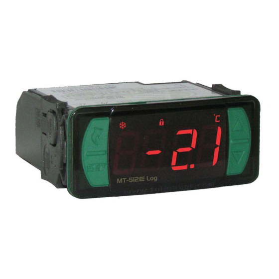
5. INDICATIONS AND KEYS
Defrost indication LED
Heating indication LED
Cooling indication LED
User-friendly
Menu Key (Flatec)
Set Key
e
MT-512
Log
6. WIRING DIAGRAM
6.1. Identifications (see Images I to IV)
- Image I: MT-512E Log, supplied at 115 Vac.
- Image II: MT-512E Log, supplied at 230 Vac.
- Image III: MT-512EL Log, supplied at 12 Vac/dc.
- Image IV: MT-512EL Log, supplied at 24Vac/dc.
IMPORTANT
THE USE OF APPROPRIATE TOOLS IS ESSENTIAL TO AVOID DAMAGE IN THE CONNECTION AT INSTRUMENT
TERMINALS:
SCREWDRIVER SLOT 3/32''(2.4mm) FOR ADJUSTMENTS IN THE SIGNAL TERMINALS;
SCREWDRIVER PHILLIPS #1 FOR ADJUSTMENTS IN THE POWER TERMINALS;
e
MT-512
DIGITAL INDICATOR AND CONTROLLER FOR
HEATING OR REFRIGERATION WITH NATURAL DEFROST
THROUGH COMPRESSOR SHUTDOWN AND
INTERNAL DATALOGGER
Manual
Function
Control functions
Serial
defrost
lock
shutdown
programming
e
Log is equipped with 1 powerful 2HP relay, 1
Functions lockdown indication LED
Control functions OFF indication LED
Temperature unit indication LED
Upper Key
Lower Key
Log
IP 65
LOG
FRONT
Datalogger
Supervisory
Degrees
system
of protection
Image I: MT-512E Log - 115Vac
A
B
D1
WIRING
TERMINALS
TEMPERATURE
SENSOR
Image
II:
MT-512E Log
A
B
D1
WIRING
TERMINALS
TEMPERATURE
SENSOR
Image III: MT-512EL Log - 12Vac/dc
A
B
D1
WIRING
TERMINALS
POWER
12Vac/dc
TEMPERATURE
SENSOR
Image IV: MT-512EL Log - 24Vac/dc
A
B
D1
WIRING
TERMINALS
POWER
24Vac/dc
TEMPERATURE
SENSOR
6.2. Temperature sensor connection
- Connect the sensor wires to terminals '1 and 2': the polarity is not relevant.
- Length of the sensor cables can be increased by user himself to up to 200 meters, using a PP 2x24
AWG cable.
- For immersion in water, use a thermowell (Image VI - item 13), available in the Full Gauge Controls
product line (sold separately).
e
e
Lo g
Lo g
MT -5 12
MT -5 12
CONTROLLER
WIRING
TERMINALS
NC
NO
COMMON
115 Vac
LOAD
}
POWER
GRID
- 230 Vac
CONTROLLER
WIRING
TERMINALS
NC
NO
COMMON
230 Vac
LOAD
}
POWER
GRID
CONTROLLER
WIRING
TERMINALS
S u r g e P r o t e c t i v e
Device (SPD)
NC
NO
COMMON
(sold separately)
W i r i n g d i a g r a m f o r
instalation of SPD in
LOAD
magnectic contactor
A1 and A2 are the terminals of
the contactor coil.
}
POWER
GRID
CONTROLLER
W i r i n g d i a g r a m f o r
WIRING
instalation of SPD in line
TERMINALS
with loads
For direct drive take in to
consideration the specified
maximum current.
NC
NO
COMMON
LOAD
}
POWER
GRID
evolution
E251415
A1
A2
LOAD
Advertisement
Table of Contents

Summary of Contents for Full Gauge MT-512e Log
- Page 1 AWG cable. SCREWDRIVER SLOT 3/32''(2.4mm) FOR ADJUSTMENTS IN THE SIGNAL TERMINALS; - For immersion in water, use a thermowell (Image VI - item 13), available in the Full Gauge Controls SCREWDRIVER PHILLIPS #1 FOR ADJUSTMENTS IN THE POWER TERMINALS; product line (sold separately).
-
Page 2: Assembling Procedure
Use the pins according to table below, considering the set version: 8.3.1. Adjusting setpoint (desired temperature) Hold the key down for 2 seconds until the message[SET,]. is displayed. The adjusted control Pins MT-512E Log MT-512EL Log temperature will be displayed when the key is released. 9 and 10 115 Vac 12 Vac/dc <... -
Page 3: Date And Time Adjustment
< > 8.3.8. Manual datalogger activation to change the value and press when ready to save the configured value and return to the function menu. To leave the menu and return to the normal operating mode (temperature indication), The manual activation requires function F21 to be configured with the value 2. By holding down the keys <... -
Page 4: Glossary Of Acronyms
“locked” temperature value again, or after 15 minutes in refrigeration (as a safety measure). [emem] Contact Full Gauge Controls. F13 - Delay in turning on device: When the device is switched on its control output will remain disabled, delaying the beginning of the [ClO,] Adjustment or visualization of the date and time. - Page 5 (of the same The materials used in the packaging of Full Gauge products are 100% recyclable. Try to controller), for example. It has three types of connections to load or unload the parameters: perform disposal through specialized recyclers.
Need help?
Do you have a question about the MT-512e Log and is the answer not in the manual?
Questions and answers