
Related Manuals for ATEN CS19208


Summary of Contents for ATEN CS19208
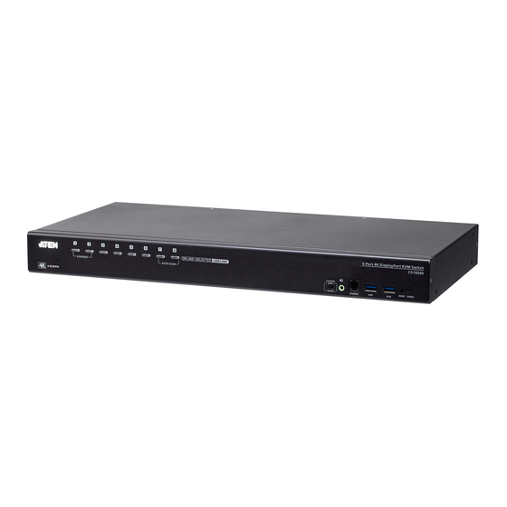
- Page 1 8/16-Port USB 3.0 4K DisplayPort KVM Switch CS19208 / CS19216 User Manual www.aten.com...
-
Page 2: Emc Information
CS19208 / CS19216 User Manual EMC Information FEDERAL COMMUNICATIONS COMMISSION INTERFERENCE STATEMENT: This equipment has been tested and found to comply with the limits for a Class A digital device, pursuant to Part 15 of the FCC Rules. These limits are designed to provide reasonable protection against harmful interference when the equipment is operated in a commercial environment. -
Page 3: User Information
CS19208 / CS19216 User Manual User Information Online Registration Be sure to register your product at our online support center: International http://eservice.aten.com Telephone Support For telephone support, call this number: International 886-2-8692-6959 China 86-400-810-0-810 Japan 81-3-5615-5811 Korea 82-2-467-6789 North America... -
Page 4: Package Contents
© Copyright 2020 ATEN® International Co., Ltd. Manual Date: 2020-10-12 ATEN and the ATEN logo are registered trademarks of ATEN International Co., Ltd. All rights reserved. All other brand names and trademarks are the registered property of their respective owners. -
Page 5: Table Of Contents
Front View CS19208 ........ - Page 6 CS19208 / CS19216 User Manual 3. Basic Operation Hot Plugging ..........25 Hot Plugging KVM Ports .
- Page 7 CS19208 / CS19216 User Manual 6. Keyboard Emulation Mac Keyboard ..........57 Sun Keyboard .
- Page 8 CS19208 / CS19216 User Manual CS19208 / CS19216 Connection Tables ......91 Specifications ..........93 Administrator Login Failure .
-
Page 9: About This Manual
CS19208 / CS19216 User Manual About this Manual This User Manual is provided to help you get the most from your CS19208 / CS19216 system. It covers all aspects of installation, configuration and operation. An overview of the information found in the manual is provided below. -
Page 10: Conventions
For information about all ATEN products and how they can help you connect without limits, visit ATEN on the Web or contact an ATEN Authorized Reseller. Visit ATEN on the Web for a list of locations and telephone numbers: International http://www.aten.com... -
Page 11: Introduction
Government, Production, Telecom, Finance, Medical Healthcare, Industrial Automation, etc. Note: The CS19208 / CS19216 offers two types of installation – 1) standalone/ cascade; and 2) multi-display – that require different cabling setups. Therefore, the functions of both types are not available in one installation. -
Page 12: Features
For PC compatible computers. Mac and Sun computers must use the USB cable connections (see Cables, page 5). Features One USB console controls up to eight (CS19208) or sixteen (CS19216) DisplayPort interface computers and two additional USB 3.0 peripheral devices ... - Page 13 Multiplatform support – Windows, Linux, Mac, and Sun Firmware upgradable Supports multimedia, wireless keyboards and mouse Note: 1. Cascading between CS19208 and CS19216 is available. 2. HD audio through HDMI and DisplayPort channel cannot be switched independently.
-
Page 14: Requirements
CS19208 / CS19216 User Manual Requirements Console An HDMI compatible monitor capable of the highest possible resolution that you will be using on any computer in the installation A DisplayPort compatible monitor capable of the highest possible resolution that you will be using on any computer in the installation Note: For multi-display installations, multiple monitors are required. -
Page 15: Cables
Sun Soloaris 11.3 and higher 10.6 and higher Note: Supports Linux Kernel 2.6 and higher. The CS19208 / CS19216 has a built-in USB3.1 hub, and does not support PCs or operating systems that do not support USB3.1. -
Page 16: Components
CS19208 / CS19216 User Manual Components Front View CS19208 & Front View CS19216 &... - Page 17 Note: The speakers plugged in here have priority over those in the rear panel. Firmware The firmware upgrade cable that transfers the firmware Upgrade Port upgrade data from the administrator's computer to the CS19208 / CS19216 plugs into this RJ-11 connector.
- Page 18 CS19208 / CS19216 User Manual Component Description USB 3.1 Gen USB 3.1 peripherals (printers, scanners, etc.) can plug into this 1 Peripheral port (this may require an extra power adapter). Hub Section Note: The USB 3.1 hub cannot be accessed through the switch by computers on the second level of a cascaded installation.
-
Page 19: Rear View Cs19208
1. Introduction Rear View CS19208 Rear View CS19216 Component Description Grounding Terminal The grounding wire used to ground the switch attaches here. Power Jack The power adapter cable plugs in here. Audio Jack The cables from your main speakers plug in here. - Page 20 CS19208 / CS19216 User Manual This Page Intentionally Left Blank...
-
Page 21: Hardware Setup
Consult your dealer to find out which custom KVM cables best fit your needs. Installation Types The CS19208 / CS19216 offers two types of installation – 1) standalone/ cascade; and 2) multi-display – that require different cabling setups. Therefore, the functions of both types are not available in one installation. See the following sections in this chapter for details about the different cabling requirements. -
Page 22: Stacking And Rack Mounting
CS19208 / CS19216 User Manual Stacking and Rack Mounting The CS19208 / CS19216 can be stacked on the desktop or rack mounted at the front or rear of the rack. The following sections take you through the procedures for each method. -
Page 23: Rack Mounting - Front
2. Hardware Setup Rack Mounting – Front 1. Remove the screws, one each from the left and right sides near the front of the unit. 2. Use the M3 x 6 Phillips hex head screws supplied with the rack mounting kit to screw the rack mounting brackets into the sides near the front of the unit. - Page 24 CS19208 / CS19216 User Manual 3. Place the KVM switch in the rack. Position it so that the holes in the mounting brackets line up with the holes in the rack. Secure the mounting brackets to the front of the rack.
-
Page 25: Rack Mounting - Rear
2. Hardware Setup Rack Mounting – Rear 1. Remove the screws, one each from the left and right sides of the switch near the rear of the unit. 2. Use the M3 x 6 Phillips hex head screws supplied with the rack mounting kit to screw the rack mounting brackets into the sides near the rear of the unit. - Page 26 CS19208 / CS19216 User Manual 3. Place the KVM switch in the rack. Position it so that the holes in the mounting brackets line up with the holes in the rack. Secure the mounting brackets to the rear of the rack.
-
Page 27: Single Stage Installation
2. Hardware Setup Single Stage Installation To set up your single stage CS19208 / CS19216 installation, refer to the installation diagram on page 18 (the numbers in the diagrams correspond to the steps, below), and do the following: 1. Ground the CS19208 / CS19216 by connecting one end of a grounding wire to the Grounding Terminal and the other end to a suitable grounded object. -
Page 28: Single Stage Installation Diagram
Power Jack. Now the CS19208 / CS19216 is turned on. 9. Power on the computers. Note: Make sure the computers and devices that the CS19208 / CS19216 connects to are also properly grounded. Single Stage Installation Diagram... -
Page 29: Two Stage Cascade
Two Stage Cascade To control even more computers, additional CS19208 / CS19216 units can be cascaded from the KVM ports of the First Stage unit. The cascaded CS19208 / CS19216s that connect back to the First Stage unit are considered Second Stage units. - Page 30 The USB 3.1 hub cannot be accessed through the switch by computers on the second level of a cascaded installation. Make sure the computers and devices that the CS19208 / CS19216 connects to are also properly grounded.
-
Page 31: Two Stage Installation Diagram
2. Hardware Setup Two Stage Installation Diagram USB DisplayPort KVM Cable Set... -
Page 32: Multi-Display Installation
CS19208 / CS19216 User Manual Multi-display Installation The CS19208 / CS19216’s multi-display feature allows you to stack two, three, four, or up to 8 units in a dual/triple/quad-display/multi-display installation to control up to seven (CS19208) or fifteen (CS19216) computers at once. This... -
Page 33: Multi-Display Installation Diagram
17 for full details. All video, audio and peripheral devices must be connected to the first switch. 6. Power up the CS19208 / CS19216 units, starting with the first switch, and then power on the computers. Note: Make sure the computers and devices that the CS19208 / CS19216 connects to are also properly grounded. -
Page 34: Grouping Ports Into "Vertical" Channels
Port 7s become Channel 7. The ports will all be switched at the same time, channel by channel. Depending on the number of stages in your stack, a CS19208 / CS19216 installation offers dual display (two stages), triple display (three stages), quad display (four stages) or multi-display (up to 8 stages) scenarios. -
Page 35: Basic Operation
Basic Operation Hot Plugging The CS19208 / CS19216 supports hot plugging – components can be removed and added back into the installation by unplugging their cables from the ports without the need to shut the unit down. In order for hot plugging to work... -
Page 36: Port Selection
Use the front panel pushbutton switches to manually switch to a port. Port ID Numbering Each port on a CS19208 / CS19216 installation is assigned a unique Port ID. You can directly access any computer on any level of the installation by specifying the Port ID that the computer is connected to –... -
Page 37: Powering Off And Restarting
3. Basic Operation Powering Off and Restarting If it becomes necessary to power off a CS19208 / CS19216, do the following before restarting it: 1. Unplug the CS19208 / CS19216 from its power source. 2. Shut down all the computers that are attached to it. - Page 38 CS19208 / CS19216 User Manual This Page Intentionally Left Blank...
-
Page 39: Osd Operation
Manufacturing Number The “MFG Number” (Manufacturing Number) is an internal serial number used by ATEN’s factory and technical support staff to identify products. This number does not affect products’ warranty. If your product requires after-sales services, you may provide the MFG Number to ATEN’s sales or technical support staff to identify the product and model number. -
Page 40: Osd Hotkey
OSD Hotkey You can display the OSD on the console monitor while also viewing the display of any port on the CS19208 / CS19216 by pressing the [Scroll Lock] key twice. Note: You can optionally change the OSD hotkey to the Ctrl key, in which case you would press [Ctrl] twice (see OSD HOTKEY, page 35). -
Page 41: Osd Main Screen Headings
4. OSD Operation b) To enable the Mouse Emulation via hotkeys, see Mouse Emulation Control, page 53. If the port list is collapsed, click on a switch number, or move the highlight bar to it then press the Enter key to expand the list. Similarly, to collapse a switch’s port list, click on the switch number, or move the highlight bar to it then press the right Enter key to collapse the list. -
Page 42: Osd Functions
CS19208 / CS19216 User Manual OSD Functions OSD functions are used to configure and control the OSD. For example, you can rapidly switch to any port, scan selected ports, limit the list you wish to view, designate a port as a quick view port, create or edit a port name, or make OSD setting adjustments. -
Page 43: F1: Go To
4. OSD Operation F1: Go To Clicking or pressing [F1] activates the Go To function. Go To allows you to switch directly to a port by keying in the port's ID. Enable mouse emulation for independent switching (see page 40), for this function to work. ... -
Page 44: F2: List
CS19208 / CS19216 User Manual F2: List Clicking or pressing [F2] activates the List function. This function lets you broaden or narrow the scope of which ports the OSD displays on the main screen. The submenu choices and their meanings are given in the table below. -
Page 45: F3: Set
4. OSD Operation F3: Set Clicking or pressing [F3] activates the Set function. This function allows the administrator and each user to set up his own working environment. A separate profile for each is stored by the OSD and is activated according to the username that was provided during login. - Page 46 CS19208 / CS19216 User Manual Port ID Display Determines how long a port ID displays on the monitor after a port Duration change has taken place. The choices are: 3 Seconds (default) and Always Off. Port ID Display Selects how the port ID is displayed: the port number plus the port Mode name (Port Number + Port Name) (default);...
-
Page 47: F4: Admin
4. OSD Operation F4: Admin Clicking or pressing [F4] activates Admin function. F4 is an administrator only function. It allows the administrator to configure and control the overall operation of the OSD. To change a setting, click on the settings item you want to configure, or use the up and down arrow keys to move the highlight bar to it then press [Enter]. - Page 48 CS19208 / CS19216 User Manual Setting Function Set User Login This function is used to set usernames and passwords for the administrator and users: 1. Usernames and passwords for one administrator and four users can be set. 2. After you select the administrator field or one of the user fields, a field that allows you to key in the username and password appears.
- Page 49 4. OSD Operation Edit Port Names To help remember which computer is attached to a particular port, every port can be given a name. This function allows the administrator to create, modify, or delete port names. To edit a port name: 1.
- Page 50 / Restore Management Utility lets you backup the current OSD configuration of the CS19208 / CS19216, and restore it when necessary. Storing the OSD configuration settings is useful when deploying more than one installation that uses the same settings. See OSD Configuration Backup/Restore, page 84, for full details.
-
Page 51: F5: Skp
4. OSD Operation F5: SKP Clicking or pressing [F5] invokes Skip (SKP) mode. This function enables you to easily skip backward or forward – switching the console focus from the currently active computer port to the previous or next accessible one. Enable mouse emulation for Skip mode to work (see page 40). -
Page 52: F6: Brc
CS19208 / CS19216 User Manual F6: BRC F6 is an administrator only function. Clicking or pressing [F6], invokes Broadcast (BRC) mode. When this function is in effect, commands sent from the console are broadcast to all available computers on the installation. -
Page 53: F7: Scan
4. OSD Operation F7: SCAN Clicking or pressing [F7] invokes Auto Scan mode. This function allows you to automatically switch among the available computers at regular intervals so that you can monitor their activity without having to take the trouble of switching yourself. Enable mouse emulation for Auto Scan to work (see page 40). -
Page 54: F8: Logout
CS19208 / CS19216 User Manual F8: Logout Clicking , or pressing [F8] logs you out of OSD control of the computers, and blanks the console screen. This is different from simply pressing [Esc] when you are at the main screen to deactivate the OSD. With... -
Page 55: Hotkey Operation
Hotkey Operation Hotkey Port Control Hotkey port control allows you to provide KVM focus to a particular computer directly from the keyboard. The CS19208 / CS19216 provides the following hotkey port control features: Selecting the Active Port Auto Scan Mode Switching ... -
Page 56: Hotkey Setting Mode
CS19208 / CS19216 User Manual Hotkey Setting Mode Hotkey Setting Mode is used to set up your CS19208 / CS19216 switch configuration. All operations begin with invoking Hotkey Setting Mode (HSM). Invoking HSM To invoke HSM do the following: 1. Press and hold down [Num Lock]. -
Page 57: Select The Active Port
5. Hotkey Operation Select the Active Port Each KVM port is assigned a port ID (see Port ID Numbering, page 26). You can directly access any computer on the installation with a hotkey combination that specifies the port ID of the KVM port that a computer is connected to. To access a computer using hotkeys: 1. -
Page 58: Auto Scan Mode
CS19208 / CS19216 User Manual Auto Scan Mode Auto Scan automatically switches, at regular intervals, among all the KVM ports that have been set as accessible under Scan–Skip Mode, so that their activity can be monitored automatically. See Scan–Skip Mode on page 36 for more information. -
Page 59: Skip Mode
5. Hotkey Operation Skip Mode This feature allows you to switch between computers in order to monitor them manually. You can dwell on a particular port for as long as you like – as opposed to auto-scanning, which automatically switches after a fixed interval. To invoke Skip mode, key in the following hotkey combination: 1. -
Page 60: Keyboard / Mouse Reset
CS19208 / CS19216 User Manual Keyboard / Mouse Reset If the keyboard or mouse cease to function on the computer connected to the currently selected port, you can perform a keyboard / mouse reset on the computer. This function is essentially the same as unplugging and replugging the keyboard and mouse on the target computer. -
Page 61: Osd Hotkey Control
5. Hotkey Operation OSD Hotkey Control The OSD Hotkey (see OSD Hotkey, page 35) can be toggled between [Scroll Lock], [Scroll Lock] and [Ctrl], [Ctrl]. To toggle the OSD Hotkey, key in the following hotkey combination: 1. Invoke HSM with the [Num Lock] + [-] or [Ctrl] + [F12] combination. 2. -
Page 62: Restore Default Values
To invoke Video DynaSync, do the following: 1. Invoke HSM with the [Num Lock] + [-] or [Ctrl] + [F12] combination. 2. Press [D]. Note: If the monitor is disconnected and reconnected, the CS19208 / CS19216 re-executes Video DynaSync. -
Page 63: Edid Mode
5. Hotkey Operation EDID Mode To configure an EDID mode for the CS19208 / CS19216, do the following: 1. Invoke HSM with the [Num Lock] + [-] or [Ctrl] + [F12] combination. 2. Press [V]. 3. Key in [1], [2], [3], or [4], the Function of [1], [2], [3], and [4] keys is... -
Page 64: Hsm Summary Table
CS19208 / CS19216 User Manual HSM Summary Table After invoking HSM (see page 46), key in one of the following keys to perform the corresponding function: Function [PN] [Enter] Switches KVM, Audio, and USB focus directly to the computer that corresponds to that port ID. (PN = port... - Page 65 n = 1, read DisplayPort monitor’s EDID. n = 2, read HDMI monitor’s EDID. n = 3, ATEN default EDID mode (Full HD 1920 x 1080 @60Hz). n = 4, Remix mode. Enables/Disables mouse emulation. [ ← ] Skips to the previous computer on the list, in skip mode.
- Page 66 CS19208 / CS19216 User Manual This Page Intentionally Left Blank...
-
Page 67: Keyboard Emulation
Chapter 6 Keyboard Emulation Mac Keyboard The PC compatible (101/104 key) keyboard can emulate the functions of the Mac keyboard. The emulation mappings are listed in the table below. PC Keyboard Mac Keyboard [Shift] Shift [Ctrl] Ctrl [Ctrl] [1] [Ctrl] [2] [Ctrl] [3] [Ctrl] [4] [Alt]... -
Page 68: Sun Keyboard
CS19208 / CS19216 User Manual Sun Keyboard The PC compatible (101/104 key) keyboard can emulate the functions of the Sun keyboard when the Control key [Ctrl] is used in conjunction with other keys. The corresponding functions are shown in the table below. -
Page 69: Rs-232 Operation
CS19208 / CS19216 installation are managed via HyperTerminal sessions on systems that are running Windows. In order to use this feature to send commands to the CS19208 / CS19216, you must first download and install a HyperTerminal application. -
Page 70: Rs-232 Pin Assignments
CS19208 / CS19216 User Manual RS-232 Pin Assignments Pin assignments for the CS19208 / CS19216’s Firmware Upgrade Port that is used for connecting to a serial terminal are given in the table, below: Assignment TXD: Transmit Data RXD: Receive Data... -
Page 71: Console Login - Hyperterminal
Chapter 7. RS-232 Operation Console Login - HyperTerminal Once a physical connection from the computer to the CS19208 / CS19216 has been made, you can establish a HyperTerminal session using the instructions below. 1. Open the HyperTerminal application, and configure the port settings for COM1 port, then click OK. -
Page 72: Rs-232 Commands
RS-232 commands to control the switch from the computer. When RS-232 control is enabled via the Open + [Enter] command, the CS19208 / CS19216’s front panel pushbuttons, OSD, hotkeys, and remote control commands will be disabled - until the RS-232 control is disabled. Verification... -
Page 73: Login
Chapter 7. RS-232 Operation Login The Login command allows you to login to the CS19208 / CS19216 and begin sending RS-232 commands. When you login the RS-232 link is “opened”, and the CS19208 / CS19216 will not respond to front panel pushbuttons, hotkeys, OSD, or remote control commands - until the RS-232 link is closed (see Switch Port, page 67). -
Page 74: Logout
CS19208 / CS19216 User Manual Logout The Logout commands allows you to logout of the CS19208 / CS19216 and close the RS-232 link. Use the Formula - to set Parameters - to create a Command. Formulas: Command + [Enter] Parameters:... -
Page 75: Open / Close Rs-232 Link
The Open and Close RS-232 Link commands allows you to open/close the link between the computer sending RS-232 commands and the CS19208 / CS19216. When the link is open, the CS19208 / CS19216 only accepts RS-232 commands and will not respond to front panel pushbuttons, OSD, hotkeys, and remote control commands - until the link is closed. -
Page 76: Set Baud Rate
CS19208 / CS19216 User Manual Set Baud Rate The Set Baud Rate command allows you to configure the baud rate setting for the serial port connection. The default baud rate is 19200. Use the Formula - to set Parameters - to create a Command. -
Page 77: Switch Port
Parameters: Command Description Switch Port Command Control Description Input Port Number xx= 01~08 (CS19208); 01~16 (CS19216) Enter Description Enter Enter and send out command Switch Port Commands The available formula for the Switch Port command is as follows: 1. Command + Control + [Enter]... -
Page 78: Hotkey Setting
CS19208 / CS19216 User Manual Hotkey Setting The Hotkey Setting command allows you to change the hotkey used to invoke the HSM (Hotkey Setting Mode). The default hotkey is [Num Lock] + [-]. Use the Formula - to set Parameters - to create a Command. -
Page 79: Osd Hotkey
Chapter 7. RS-232 Operation OSD Hotkey The OSD Hotkey command allows you to change the hotkey used to invoke the OSD. The default hotkey is [Scroll][Scroll]. Use the Formula - to set Parameters - to create a Command. Formulas: Command + Control + [Enter] Parameters: Command Description... -
Page 80: Usb Reset
CS19208 / CS19216 User Manual USB Reset The USB Reset command allows you to reset the USB connection. The default USB reset setting is off. Use the Formula - to set Parameters - to create a Command. Formulas: Command + Control + [Enter]... -
Page 81: Restore Default Settings
Chapter 7. RS-232 Operation Restore Default Settings The Restore Default Settings command allows you to reset all of the CS19208 / CS19216’s settings back to the default. The default setting is off. Use the Formula - to set Parameters - to create a Command. -
Page 82: Firmware Upgrade
CS19208 / CS19216 User Manual Firmware Upgrade The Firmware Upgrade command allows you to enable the firmware upgrade mode. The default setting is off. Use the Formula - to set Parameters - to create a Command. Formulas: Command + Control+ [Enter]... -
Page 83: Kvm Status
Chapter 7. RS-232 Operation KVM Status The KVM Status command allows you to display read-only information about the CS19208 / CS19216’ current configuration status. The default setting is off. Use the Formula - to set Parameters - to create a Command. Formulas:... -
Page 84: Edid Mode See Vs482B
CS19208 / CS19216 User Manual EDID Mode see VS482B The EDID Mode command allows you to set EDID mode for the CS19208 / CS19216. Use the Formula - to set Parameters - to create a Command. Formulas: Command + Control + [Enter]... -
Page 85: Broadcast Mode
Enter and send out command Broadcast Mode Command The available formula for the KVM Status command is as follows: 1. Command + Control + [Enter] For example, to enable the CS19208 / CS19216’s broadcast mode, type the following: broadcast on [Enter]... - Page 86 CS19208 / CS19216 User Manual This Page Intentionally Left Blank...
-
Page 87: The Firmware Management Utility
Introduction The purpose of the Windows-based Firmware Management Utility is to provide an automated process for upgrading all CS19208 / CS19216 switches in an installation. The program comes as part of a Firmware Upgrade Package that is specific for each device. -
Page 88: Preparation
CS19208 / CS19216 User Manual Preparation To prepare for the firmware upgrade, do the following: 1. Use the Firmware Upgrade Cable provided with this unit to connect a COM port on your computer to the Firmware Upgrade Port of your switch. -
Page 89: Starting The Upgrade
8. The Firmware Management Utility Starting the Upgrade To upgrade the firmware: 1. Run the downloaded firmware upgrade package file either by double- clicking the file icon, or by opening a command line and entering the full path to it. The Firmware Upgrade Utility welcome screen appears: Note: The screens shown in this section are for reference only. - Page 90 CS19208 / CS19216 User Manual 3. Click Next to continue. The Firmware Upgrade Utility main screen appears. The devices capable of being upgraded are listed in the Device List panel: CS19208/CS19216 [MAIN].. 4. As you select a device in the list, its description appears in the Device Description panel.
- Page 91 The firmware [Ver 1.0.] is not newer than the current firmware [Ver 1.0.090] in device CS19208/CS19216 [MAIN]: 000 Continue the upgrade? [Yes/No] If you didn't enable Check Firmware Version, the Utility installs the upgrade files without checking whether they are a higher level, or not.
-
Page 92: Upgrade Succeeded
CS19208 / CS19216 User Manual Upgrade Succeeded After the upgrade has completed, a screen appears to inform you that the procedure was successful. CS19208/CS19216 [MAIN].. CS19208/CS19216 [MAIN] :000 CS19208/CS19216 [MAIN] CS19208/CS19216 [MAIN]000:OK Click Finish to close the Firmware Upgrade Utility. -
Page 93: Firmware Upgrade Recovery
8. The Firmware Management Utility Firmware Upgrade Recovery There are three conditions that call for firmware upgrade recovery: When a firmware upgrade is manually aborted. When the mainboard firmware upgrade fails. When the I/O firmware upgrade fails. To perform a firmware upgrade recovery, do the following: 1. -
Page 94: Osd Configuration Backup/Restore
Backup Follow these steps to store a backup file to a local computer: 1. Make sure your computer is connected to the CS19208 / CS19216. See Preparation, page 78, and follow steps 1–3. 2. When you have selected the F4 Admin function, scroll down to OSD Config Backup / Restore. -
Page 95: Restore
8. The Firmware Management Utility Restore Follow these steps to restore a backup file from a local computer: 1. Do steps 1 to 3 of the previous section. See Backup, page 84. 2. Click Restore to recover an OSD configuration stored in the local computer. - Page 96 CS19208 / CS19216 User Manual This Page Intentionally Left Blank...
-
Page 97: Appendix
Appendix Safety Instructions General This product is for indoor use only. Read all of these instructions. Save them for future reference. Follow all warnings and instructions marked on the device. Do not place the device on any unstable surface (cart, stand, table, etc.). If the device falls, serious damage will result. - Page 98 CS19208 / CS19216 User Manual If the following conditions occur, unplug the device from the wall outlet and bring it to qualified service personnel for repair. The power cord or plug has become damaged or frayed. Liquid has been spilled into the device.
-
Page 99: Rack Mounting
Appendix Rack Mounting Before working on the rack, make sure that the stabilizers are secured to the rack, extended to the floor, and that the full weight of the rack rests on the floor. Install front and side stabilizers on a single rack or front stabilizers for joined multiple racks before working on the rack. -
Page 100: Technical Support
CS19208 / CS19216 User Manual Technical Support International For online technical support – including troubleshooting, documentation, and software updates: http://support.aten.com For telephone support, see Telephone Support, page iii: North America Email Support support@aten-usa.com Online Troubleshooting http://www.aten-usa.com/support Technical Documentation... -
Page 101: Cs19208 / Cs19216 Connection Tables
Appendix CS19208 / CS19216 Connection Tables The following tables indicate the relationship between the number of Primary View units and the number of computers that they control: (First Level) + (Second Level) CS19208 CS19208 Computers 1 - 8 8 -15... - Page 102 CS19208 / CS19216 User Manual (First Level) + (Second Level) CS19216 CS19208 Computers Computers 1 - 16 72 - 79 16 -23 79 - 86 23 - 30 86 - 93 30 - 37 93 - 100 37 - 44...
-
Page 103: Specifications
Appendix Specifications Function CS19208 CS19216 Computer Direct Connections Max. 128 (via Cascade) 256 (via Cascade) Port Selection OSD, Hotkey, Pushbutton, RS-232 Commands Connectors Console 1 x USB Type A Female Ports Video 1 x DisplayPort Female 1 x HDMI Female... -
Page 104: Administrator Login Failure
4. When the front panel LEDs flash, power off the switch. 5. Remove the jumper cap from J29. 6. Close the housing and start the CS19208 / CS19216 back up. After you start back up, you can use the default login procedure (see OSD... -
Page 105: Factory Default Hotkeys And Settings
Appendix Factory Default Hotkeys and Settings Setting Default OSD Hotkey [Scroll Lock] [Scroll Lock] Invoking HSM Hotkey [Number Lock] [-] Auto Scan Interval 5 seconds Mouse Emulation Enabled EDID Mode DisplayPort Monitor’s EDID Beeper Enabled Video DynaSync Enabled... -
Page 106: Limited Warranty
What is covered by the Limited Hardware Warranty ATEN will provide a repair service, without charge, during the Warranty Period. If a product is detective, ATEN will, at its discretion, have the option to (1) repair said product with new or repaired components, or (2) replace the entire product with an identical product or with a similar product which fulfills the same function as the defective product. - Page 107 Index Command Mode 38 OSD 37 Activate Beeper 41 Selecting the Active Port 49 ADM 39 Hotkey Mode Auto Scanning 45 exiting 48 Invoking Auto Scan 50 Hotkey Port Control 47 Pausing Auto Scan 50 Scan Duration 38 Stopping 50 Installation two stage 19 Beeper...
- Page 108 CS19208 / CS19216 User Manual Manual 28 Rack Mounting 91 ports SCAN 45 quick view 41 Scan Duration 38 set operating system 42 SCAN/SKIP MODE 38 Powering Off and Restarting 29 Screen Blanker 38 Selecting the Active Port 49 SET 37...
Need help?
Do you have a question about the CS19208 and is the answer not in the manual?
Questions and answers