
Related Manuals for ABB MNS-MCC


Summary of Contents for ABB MNS-MCC
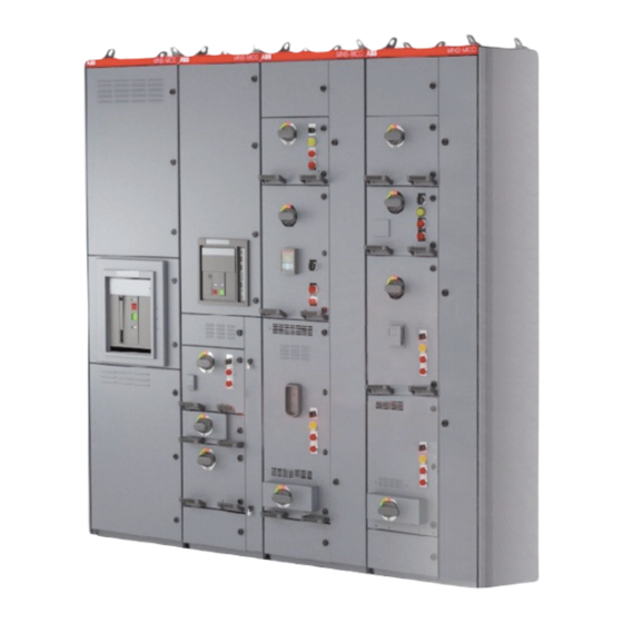
- Page 1 I N S TA L L AT I O N , O P E R AT I O N S A N D M A I N T E N A N C E M A N UA L MNS-MCC...
-
Page 3: Table Of Contents
TA B L E O F C O N T E N T S — Table of contents 04 – 05 Important user information 06 – 16 General information and system description 17 – 20 Packaging and handling 21 – 36 Installation 36 –... -
Page 4: Important User Information
M N S - M C C LO W V O LTA G E M OTO R C O N T R O L C E N T E R — Important user information ABB shall not assume any liability for any of the Keep this manual available for the installation, following: operation and maintenance of this equipment. - Page 5 ABB investigate all such ways. Anyone using service procedures or tools, whether or not Notice – Indicates a statement of recommended by ABB, must satisfy himself or...
-
Page 6: General Information And System Description
General information and system description System overview Withdrawable units feature a multi-position handle The MNS-MCC motor control center consists that controls the disconnecting means as well as a of one or more vertical metal cabinets referred mechanical interlock, preventing the unit from to as “sections.”... - Page 7 ANSI C84.1 (Voltage Tolerances for North America), Seismic Qualification to IBC-2018 and CBC-2019, AC156, “Shake-Table Testing for Nonstructural The MNS-MCC is designed, tested and constructed Components and Systems,” and ASCE/SEI 7-05, in accordance with the following industry standards “Minimum Design Loads for Buildings and Other...
- Page 8 M N S - M C C LO W V O LTA G E M OTO R C O N T R O L C E N T E R — MNS-MCC Standard configuration structure End sections are designed to allow for the addition...
- Page 9 I N S TA L L AT I O N , O P E R AT I O N S A N D M A I N T E N A N C E M A N U A L —...
- Page 10 M N S - M C C LO W V O LTA G E M OTO R C O N T R O L C E N T E R — Mechanical design Bus bar compartments 05 Frame, enclosure and inside constructions The basic mechanical design includes (Fig.
- Page 11 I N S TA L L AT I O N , O P E R AT I O N S A N D M A I N T E N A N C E M A N U A L —...
- Page 12 M N S - M C C LO W V O LTA G E M OTO R C O N T R O L C E N T E R — Vertical distribution bus bar Equipment compartment 08 Vertical distribution bus bar The MCC standard vertical bus bars are 800A and The equipment compartment is composed of one...
- Page 13 I N S TA L L AT I O N , O P E R AT I O N S A N D M A I N T E N A N C E M A N U A L —...
- Page 14 M N S - M C C LO W V O LTA G E M OTO R C O N T R O L C E N T E R — Withdrawable units A reinforcement, non-insulated bussing system 12 Withdrawable unit These units are designed to allow quick insertion could be added to the back of the multi-function and removal of feeders, starters and other special...
- Page 15 I N S TA L L AT I O N , O P E R AT I O N S A N D M A I N T E N A N C E M A N U A L — Top horizontal wireway Arc resistant features 13 Top horizontal wireway The MNS-MCC has a 277.5 mm (10.9 in) top The MNS-MCC Arc Resistant provides industry — horizontal wireway. leading features that afford operators the highest...
- Page 16 M N S - M C C LO W V O LTA G E M OTO R C O N T R O L C E N T E R — 15 Arc-resistant The MNS-MCC's Arc resistant offer is distinguished The withdrawable modules for the arc resistant roof plate...
-
Page 17: Packaging And Handling
— General The maximum length for a motor control center 17 MCC General Packaging will be done using ABB standard shipping split is 1800 mm (71 in). The skid length, arrangement - shipping splits methods, unless the customer requires and for such Shipping split, will be 2100 mm (82 In), the requests special packaging. - Page 18 Note: ABB is not responsible for the what was received. damage, after delivery of the MCC or bad handlings at the time of the download.
- Page 19 I N S TA L L AT I O N , O P E R AT I O N S A N D M A I N T E N A N C E M A N U A L —...
- Page 20 M N S - M C C LO W V O LTA G E M OTO R C O N T R O L C E N T E R — • Open section doors for several hours to 22 Guide values for acclimatize the equipment.
-
Page 21: Installation
• Convenient alignment with other equipment.a If there is any evidence of damage to the • Accessibility for maintenance. equipment, contact your ABB representative to • Ambient temperature above -10° C (14° F) but not evaluate the condition of the equipment before exceeding 40°C (104°F) at 85% non-condensing... - Page 22 M N S - M C C LO W V O LTA G E M OTO R C O N T R O L C E N T E R 762 mm [30 in] minimum — 1371 mm [54 in] minimum for 23 Wall and ceiling arc resistant equipment clearance requirements...
- Page 23 I N S TA L L AT I O N , O P E R AT I O N S A N D M A I N T E N A N C E M A N U A L —...
- Page 24 M N S - M C C LO W V O LTA G E M OTO R C O N T R O L C E N T E R — c. Connect the sections using the provided 30 Bolts to connect hardware, consisting of eight (8) M6 bolts, shipping sections typically provided screwed in the shipping...
- Page 25 I N S TA L L AT I O N , O P E R AT I O N S A N D M A I N T E N A N C E M A N U A L —...
- Page 26 M N S - M C C LO W V O LTA G E M OTO R C O N T R O L C E N T E R — Splicing ground bus bar Finally replace the transparent barrier(s). 37 Bus bar connections The horizontal ground bus must be spliced —...
- Page 27 I N S TA L L AT I O N , O P E R AT I O N S A N D M A I N T E N A N C E M A N U A L —...
- Page 28 M N S - M C C LO W V O LTA G E M OTO R C O N T R O L C E N T E R — 3.7. Changing cubical height 42 Withdrawable units — Drawer Sliding (Wheel) PVC Boot 43 Unit bottom plate Power Cable Connection...
- Page 29 I N S TA L L AT I O N , O P E R AT I O N S A N D M A I N T E N A N C E M A N U A L —...
- Page 30 Should new material be required, contact the • If required exchange power cables or leave to nearest ABB sales office or representative. be used by one of the units size 12E. • Disconnect control wiring or leave to be used by one of the three units size 12E.
- Page 31 I N S TA L L AT I O N , O P E R AT I O N S A N D M A I N T E N A N C E M A N U A L —...
- Page 32 M N S - M C C LO W V O LTA G E M OTO R C O N T R O L C E N T E R — Locate conduit approximately 50 mm (2 in) above Control Terminal Blocks (CTB): 53 Control terminal block floor level.
- Page 33 I N S TA L L AT I O N , O P E R AT I O N S A N D M A I N T E N A N C E M A N U A L —...
- Page 34 To remove grease or oil on the exterior, use a solvent cleaning agent (e.g. 3M™ Prep Solvent-70 Cleaner) and a cloth or disposable wipe. Repair scratches to the paintwork with ABB supplied touch-up paint. If touch-up paint was not supplied, contact your ABB representative. See the Exterior Metal Damage Repair section in this manual for repair instructions.
- Page 35 I N S TA L L AT I O N , O P E R AT I O N S A N D M A I N T E N A N C E M A N U A L Commissioning •...
-
Page 36: Operation
• ENGAGED – Unit is full inserted and connected to these individual manuals are not supplied, power. contact your ABB representative. • ISOLATED – Unit is moved approximately 30 mm (1.2 in) out to the first detent, disconnected from Withdrawable units power. - Page 37 I N S TA L L AT I O N , O P E R AT I O N S A N D M A I N T E N A N C E M A N U A L Units status The table below shows the Unit Status based on the rotary handle position and physical location of the...
- Page 38 M N S - M C C LO W V O LTA G E M OTO R C O N T R O L C E N T E R The rotary operating handle can be locked in the For safety, you can lock the operating handle in the OFF position while the unit is in any of the following OFF positions using up to three padlocks.
-
Page 39: Maintenance
Recommended Interval: Perform annually or based ABB offers a range of preventive maintenance on your local maintenance schedule. Using the services and programs. ABB can also provide ABB- proper tool for each connection, verify the trained expert technicians and give you fast access tightness of all control and power terminals to OEM parts. - Page 40 M N S - M C C LO W V O LTA G E M OTO R C O N T R O L C E N T E R — Move a unit to the isolated position Removing a unit 61 Isolated position 1) Rotate the operating handle to the MOVE 1) To remove a unit, rotate the operating handle to...
- Page 41 I N S TA L L AT I O N , O P E R AT I O N S A N D M A I N T E N A N C E M A N U A L 3) To completely remove the unit from the MCC 3) Rotate the operating handle again to the MOVE cubicle, grasp the unit firmly and be ready to...
- Page 42 When properly adjusted, the For small areas of damage, ABB supplied touch-up operating handle will reliably spring back to the paint kits are available. To obtain a kit, contact your OFF position after being moved to the ENGAGED ABB representative.
- Page 43 I N S TA L L AT I O N , O P E R AT I O N S A N D M A I N T E N A N C E M A N U A L Article 110.16- Arc-Flash Hazard Warning of the NEC You must establish field marking requirements (Version 2014) stated:...
-
Page 44: Tightening Torques
M N S - M C C LO W V O LTA G E M OTO R C O N T R O L C E N T E R — Tightening torque — Warning: Heat generated by improper terminal Table 5. - Page 45 I N S TA L L AT I O N , O P E R AT I O N S A N D M A I N T E N A N C E M A N U A L Torque table for components fixed in sheet metal 2 mm Component Description Type...
- Page 46 M N S - M C C LO W V O LTA G E M OTO R C O N T R O L C E N T E R Torque table for components fixed in sheet metal 1.5mm Component Description Type Size Torque Nm (Nominal)
- Page 47 I N S TA L L AT I O N , O P E R AT I O N S A N D M A I N T E N A N C E M A N U A L Control And Auxiliary Contacts Component Description Type...
- Page 48 M N S - M C C LO W V O LTA G E M OTO R C O N T R O L C E N T E R Power Terminals Component Description Type Size Torque Nm (Nominal) Torque Nm (Max) Terminal screw Terminal screw Terminal screw...
- Page 49 I N S TA L L AT I O N , O P E R AT I O N S A N D M A I N T E N A N C E M A N U A L Mechanical connections thread rolling screws in METAL Material Component Description...
- Page 50 M N S - M C C LO W V O LTA G E M OTO R C O N T R O L C E N T E R...
- Page 52 Any reliance placed on such information is therefore strictly at your own risk. ABB reserves the right to discontinue any product or service at any time.