Table of Contents
Advertisement
Quick Links
Advertisement
Table of Contents

Related Manuals for ROJ AGRI Mate PCS FS

Summary of Contents for ROJ AGRI Mate PCS FS
- Page 1 PCS FS Installation Operation Maintenance ORIGINAL INSTRUCTIONS...
- Page 2 ROJ reserves the right to change at any time the contents of this manual, without notice. For any technical or commercial problem, please contact your local ROJ dealer or call directly ROJ customer service center. We will be glad to meet your needs.
- Page 3 PCS FS INSTALLATION, OPERATION AND MAINTENANCE MANUAL Edition: January 2019, Revision: Direction and Plant: Via Vercellone 11 13900 Biella (BI) - Italy Tel. +39 015 84 80 111 Fax +39 015 84 80 209 E-mail: comm@roj.com www.roj.it...
-
Page 4: Table Of Contents
Table of contents TABLE OF CONTENTS PREFACE ..................................iii Safety .................................... iv CE Marking identification ............................... iv Compliance with the European Directives and Regulations…………………………………………………………………..v Warranty and Responsibility of the Manufacturer ......................vi Other Warranty terms ..............................vi 1. GENERAL INFORMATION ............................1.1 INTRODUCTION ............................. - Page 5 Table of contents BATTERY ................................ 2.8 SPEED SENSOR ............................2.8 2.7.1 Cogwheel individual sensor ..........................2.8 2.7.2 Wheel sensor check ............................2.9 MACHINE POSITION SENSOR ........................2.10 2.8.1 Position sensor check ........................... 2.11 ECU POSITIONING ............................2.11 2.10 SDB POSITIONING…………………………………………………………………………………………………...2.12 2.11 WIRING DIAGRAM……………………………………………………………………………………………………2.12 2.11.1 Main components…………………………………………………………………………………………………….
- Page 6 Table of contents UPDATES INDEX 9/18/2014 Edition 3/29/2016 Edition 1/10/2019 Edition – Manuals for the different systems (200, FS, 150) - iii - PCS FS Kit...
-
Page 8: Preface
– Since the Machinery Directive requirements, first of all ESR in Annex I are legally binding obligations, ROJ put a special emphasis on all ESR 1.7.4 points during the drafting phase of these manual, in particular: 1. The ROJ user and maintenance manuals are supplied in the language of... -
Page 9: Safety
Machine. CE Marking identification The ROJ PCS xxx kits are CE marked on the back of the graphic display. - iv - PCS FS Kit... -
Page 10: Compliance With The European Directives And Regulations
Compliance with the European Directives and Regulations Below is and extract of the Declaration of Incorporation, drawn up in accordance with the requirements of Annex II B to 2006/42/EC Directive, by which ROJ declares that the following partly completed machinery “... -
Page 11: Warranty And Responsibility Of The Manufacturer
Any failure or improper equipment connection will void the warranty. The warranty does not apply in case of floods, fire, electrostatic/inductive discharges or in case of discharges caused by lightning or other phenomena external to the ROJ equipment. The warranty does not cover any damages to operators or other equipment/devices connected to the ROJ equipment. -
Page 12: General Information
General Information 1 - GENERAL INFORMATION 1.1 INTRODUCTION 1.1.1 The ideal solution to control and optimize the sowing process The PCS FS kit has been designed for the installation on seeders and fertilizers in order to control and optimize the entire sowing process. Thanks to the exclusive flexibility and configurability the PCS FS kit represents the best solution for volumetric seeders and fertilizers. -
Page 13: Symbols Used In This Manual
General information 1.1.4 Symbols used in this Manual This symbol highlights the notes, warnings, and points on which the reader's attention is to be drawn. This symbol indicates a particularly delicate situation that could affect the safety or proper functioning of the system. This symbol indicates the obligation to dispose of a material having an impact on the environment in accordance with the local regulations. -
Page 14: General Information And Performances
General Information GENERAL INFORMATION AND PERFORMANCES 1.2.1 Introduction The PCS FS System has been designed to be applied on volumetric seeders and fertilizers (falling within the scope of the EN 14018 norm) in order to replace the mechanical transmission that drives the rotation of the distribution discs with electrical engines, operated by their relative control system. -
Page 15: Machines On Which The Integration Of The Mentioned Partly Completed Machinery Is Foreseen
General information 1.2.3 Machines on which the integration of the mentioned partly completed machinery is foreseen • Volumetric seeders and fertilizers for tractors NOT equipped with ISOBUS connection. • Volumetric seeders and fertilizers for tractors equipped with ISOBUS connection. The current version of the system is based on a proprietary architecture and DOES NOT include the ISOBUS connection (foreseen for the coming versions). -
Page 16: Components Of The Pcs Fs Kit
General Information COMPONENTS OF THE PCS FS KIT Figure 1-1 Main components of the PCS FS kit TECHNICAL DATA Rated voltage: 12 VDC; Rated current: 4.2 A; Rated power: 80 W Geared motors Rated speed: 3000 rpm Electronic Control Processor: 80 Mhz; Flash memory 2.5 Mb; RAM: 128 Kb; NVRAM: 8 Kb; Unit CAN Bus lines: 3;... - Page 17 General information Geared motor for the seeding elements and distributors fertilizer/granular fertilizer Electronic Control Unit Graphic display Sub distribution board - 1.6 - PCS FS Kit...
-
Page 18: General Information About Safety
General Information GENERAL SAFETY INFORMATION 1.4.1 Design criteria The principles introduced by the relevant paragraphs of the following Harmonized Standards have been adopted in the design and manufacturing of the PCS FS equipment: EN ISO 12100: 2010 Safety of machinery. General principles for design. Risk assessment and risk reduction. -
Page 19: Safety Devices And Solutions
General information 1.4.2 Safety Devices and Solutions All moving parts of the geared motors are adequately protected to prevent mechanical dangers and the electrical parts of the actuator are fitted into enclosures with a minimum IP65 protection. On the guards of seeding elements, the installation of a safety device (electromechanical micro-switch or electromagnetic sensor) is foreseen which prevents the geared motor start-up under open guards conditions. -
Page 20: Warnings And Behaviour Rules For The Operator
To avoid any risk condition for the operator and any damages to the equipment, it is recommended to strictly follow the warnings and behaviour rules herein listed. ROJ will assume no liability for any damages to people and/or properties arising from the non-observance of these warnings. -
Page 21: Noise Levels
General information At the end of every maintenance work, ensure that none of the used tool has remained in proximity of the geared motors. Before restarting the machine, always restore and check the safety devices and check that they work properly, in case they have been de-activated. After any operation on the equipment all materials having an impact on the environment (such as, for example, electrical cables, components, etc.) must be properly disposed of in accordance with the applicable regulations. -
Page 22: Installation
Installation 2 - INSTALLATION DMD0 e DMD2 (MD) GEARED MOTORS FEATURES For further information, please refer to the following enclosed documents for the DMD0: • TD_1406.601_revD.pdf or later revision. • 1061_hard.pdf • 1061-cid-a.pdf • 1061_angle.pdf For the DMD2: • TD_DMD2_revI.pdf o later review. MOTORS (MD) INSTALLATION 2.2.1 General principles... -
Page 23: Outlet Shaft Dimensions
Installation 2.3.2 Outlet shaft dimensions The geared motor outlet has got a hollow shaft with the following dimensions. Figure 2-1 Outlet shaft dimensions – For further information, make reference to the file 1061-cid-a.pdf 2.3.3 Fixing flange features Please refer to 1061-cid-a.pdf 2.3.4 Tilting limits The gearbox must operate with the axis parallel to the horizontal plane. -
Page 24: Fastening
Installation 2.3.5 Transport plug The rubber part of the geared motor oil filling plug is fitted at the time of delivery, in order to avoid lubricant leaks during transport. This part is exclusively mounted for transport and should be removed before the installation. Figure 2-3 Plug with exhaust valve –... -
Page 25: Dmd2
Installation DMD2 2.4.1 Outlet shaft torque, speed and axial/radial loads The following characteristics refer to the variables of the geared motor outlet shaft (slow shaft) Designed for 12V agricultural equipment • 4,5 Nm, 80 rpm @ outlet shaft (54T01085) • Built-in driver for the brushless motor •... -
Page 26: Fixing Flange Features And Geared Motor Fastening
Installation 2.4.3 Fixing flange features and geared motor fastening This kind of geared motors can be easily fastened by fixing the reduction gear in the desired position. The fixing flange must be suited to bear an approx. weight of 1,5 Kg and 4 M4 screws are needed. -
Page 27: Alternator
Installation ALTERNATOR The alternator is used to create a supply source independent from the tractor one. The machine manufacturer should provide the mechanical solution to fasten the alternator and connect it by means of a suitable transmission belt and an overdrive, from the tractor PTO. -
Page 28: Absorbed Mechanical Power And Radial Loads
Installation 2.5.2 Absorbed mechanical power and radial loads At this speed the absorption rate can be about 4kW in the worst case (= cold alternator) (Cold Po[kW] curve). The belt and its tensioning should be sized according to the given power. The tensioning system is typically obtained using one of the two fastening elements as a pin and the other one as a moving element to adjust the chain tensioning. -
Page 29: Battery
Single cogwheel sensor The speed sensor is implemented using a hall effect speed sensor type Cherry GS102301 (P/N ROJ 50A00174) and relevant cable (P/N ROJ 05R01400). This sensor detects the speed of a phonic wheel connected to the machine drive wheel. -
Page 30: Wheel Sensor Check
Installation Figure 2-9 Example of cogwheel for speed sensor – The cogwheel should be directly fixed to the seeder drive wheel, in order to avoid rack and pinion transmissions. During the installation stage, correctly adjust the sensor/teeth distance, in order to ensure a precise count. -
Page 31: Machine Position Sensor
Installation MACHINE POSITION SENSOR It is a mechanical proximity sensor (P/N ROJ 05R01422) used to define whether the machine is in seeding position (machine lowered) or in transfer position (machine raised). Figure 2-10 Position sensor – The sensor must be fastened to the machine frame, in such a way that: •... -
Page 32: Position Sensor Check
30 poles connectors are not used in all configurations. In this case your can use the 30 poles ECU plug (P/N ROJ 05R01334) or a cable already fitted for the seeding test and pressure sensor button (P/N ROJ 05R01380). -
Page 33: Sdb Positioning
Installation 2.10 SDB POSITIONING The SDB (sub distribution board) should be mounted on a sheltered position and central to the machine, in order to make the cables routing easier. 2.11 WIRING DIAGRAM Figure 2-12 - Wiring diagram of the system with alternator The codes of the various elements are listed in the following pages. - Page 34 Installation Figure 2- - Wiring diagram of the system without alternator PCS FS Kit - 2.13 -...
-
Page 35: Main Components
Installation Figure 2-13 Battery positive pole connection detail – 2.11.1 Main components Code Description Ref. on wiring diagram 54T01068 DEMETER ECU 58G00074 AGRI-MATE GRAPHICAL CONSOLE 1406.601 PCS MD-O 56C00646 PCS SDB 12+12 56C00651 PCS SDB 3 + 3 2.11.2 ECU connection Code Description Ref. - Page 36 Installation Figure 2-14 ECU wiring diagram – PCS FS Kit - 2.15 -...
-
Page 37: Sdb And Power Supply Cables Connection
Installation 2.9.3 SDB and power supply cables connection The Figure 15 and Figure 16 show how the connections on the two versions of the board contained in the SDBs, respectively the SDB 12+12 (56C00646) and the SDB 3+3 (56C00651) are made. The boards are divided into two or four dials indicated by the letters TL , TR, BL, BR corresponding to two or four cable lead-through on the SDB junction boxes. - Page 38 Installation Figure 16 - SDB 3+3 connections Code Description Ref. on wiring diagram 05R01404 DMD DISTRIBUTION CABLE 3 POS 05R01372 DMD DISTRIBUTION CABLE 6 POS 05R01373 DMD DISTRIBUTION CABLE 7 POS 05R01310 B- / BAT- CABLE 05R01311 B+ / BAT+ CABLE 05R01312 BAT+ / SDB+ CABLE L=2000 05R01349...
- Page 39 Installation The following Figure shows the correspondence between the number of fittings and the number printed on the red corresponding conductor. Figure 17 - 05R01404 cable – 3 outputs Figure 18 - 05R01372 cable – 6 outputs Figure 19 - 05R01373 cable – 7 outputs The CAN connector (4-poles white Molex Mini-Fit jr) should be connected to the CAN socket corresponding to the dial.
- Page 40 Installation The cabling differs according to the length and type of the connector used for the seed sensor. The seed sensor connector is not present if the MDs are used for the distributors of fertilizer and micro-granular fertilizer. DMD0 Code Description Ref.
-
Page 41: Safety Switch
Installation 2.9.5 Safety switch The connection to a safety switch offers two main functions: Safety function: if the contact is open, the MD cannot rotate. Addressing function: during the MD addressing stage, the safety contact closes and confirms the device address (see paragraph 3.4.2 on section 3). The safety switch must be implemented using: “... - Page 42 Installation This page is intentionally left blank PCS FS Kit - 2.21 -...
-
Page 43: Machine Start-Up
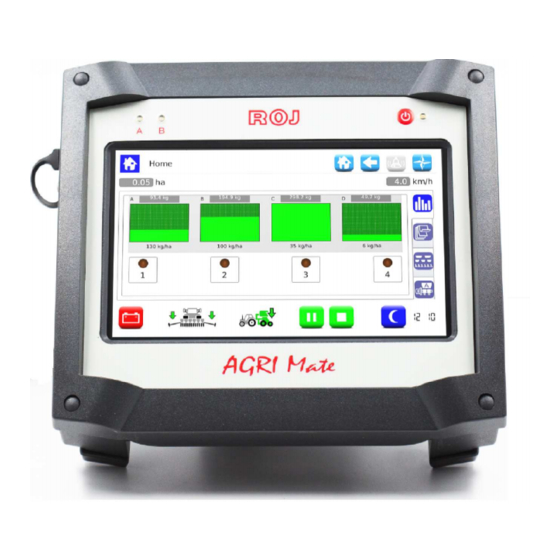
User's manual USER S MANUAL – ’ 3.1 MACHINE START-UP To start up the HMI connect the PCS FS to the battery or push/turn the corresponding battery disconnect switch located on the machine (if available). Approx. 4 seconds later, the following screen appears on the HMI display. Once the loading phase is finished, the Home screen indicated by the top left... -
Page 44: Graphic Organization
User's manual GRAPHIC ORGANIZATION Field Description Logo and name of the active window It allows to quickly return to the home screen. It allows to return to the previous screen. It allows to access the active alarms window It allows to access the complete console menu Selected tab Not selected tabs... -
Page 45: Access Levels
The default password is different for each manufacturer and can be changed by the manufacturer himself. ROJ Service This access level is foreseen for the ROJ technical support. Administrator It is the highest access level which allows to access all system functions and is reserved to the ROJ R&D... -
Page 46: Motors Addressing
User's manual MOTORS ADDRESSING At the first installation of the machine, it is necessary to address the motors, in order to associate the physical position of the motor on the machine to the logical position (Group A, Group B, Group C, Group D). The addressing procedure requires the operator s intervention and is automatically ’... -
Page 47: Machine Configuration
User's manual 3.4.1 Machine configuration Pushing the button a machine configuration window is opened where it is possible to read the number of motors associated to the A, B, C and D groups. MD addressing window Field Description It allows to modify the machine configuration If this button is pressed, the real addressing session starts To exit from the addressing window PCS FS Kit... -
Page 48: Addressing
User's manual 3.4.2 Addressing When the Addressing button is pressed, the real addressing session starts. “ ” When the addressing is active, a synopsis (summary) of the configuration set up on the previous phase is displayed. MD addressing window Field Description Motor not yet addressed Motor to be addressed... - Page 49 User's manual In case of error, press the motor symbol in order to display the dialog Unaddress “ which allows to cancel the address of one, a group or all motors: ” MD addressing window Field Description Motor not yet addressed Motor to be addressed (flashing) Addressed motor...
- Page 50 User's manual If the addressing has been completed correctly, the window is displayed as shown below and it is possible to exit by pressing the button MD addressing window Field Description It allows to modify the machine configuration If this button is pressed, the real addressing session starts To exit from the addressing window - 3.8 - PCS FS Kit...
-
Page 51: Machine Configuration
User's manual MACHINE CONFIGURATION This window allows to setup the machine during production at the manufacturer ’ premises. The setup settings of the machine can be modified only by the Manufacturer ’ Production dpt. or by the Technical Support. Path: Machine Tab Field Description... - Page 52 User's manual Single sensor (phonic wheel) Before calibrating the speed sensor used with the phonic wheel, it is possible to get a quite precise evaluation of the calibration result. For example: Supposing that the phonic wheel has been mounted on one of the seeder wheels. The wheel diameter is 64 cm.
- Page 53 User's manual Tab A/B/C/D Group Field Values range Description Number of motors associated to the group … • Group A: 1 – • Group B: 1 – • Group C: 1 – • Group D: 1 – -10000 ... 10000 Reduction gear ratio multiplied by 100 (for example: reduction gear 28.89 : 1 2889)
- Page 54 User's manual Creation of the MD/distributors association This function is enabled by pressing the button in the page for the association of the installed motors to the corresponding distributors on the machine. This operation can be carried out for all motors associated to the 4 groups. How to measure the Volume per revolution “...
- Page 55 User's manual Pressing the Start button, the auger is prefilled for the given rpm. Once this procedure is finished, the real measurement is carried out. After deciding the rpm to be run for the weighing test, press the Start button. PCS FS Kit - 3.13 -...
- Page 56 User's manual The same as for the auger prefill procedure, a progress bar is displayed to show the user how far along he/she is in the process. When the given rpm has been run, the following screen is displayed, where it is possible to input the product density and the value for the weighing carried out by the user.
-
Page 57: Seeding/Fertilization Settings
User's manual To calculate the volume per revolution the following formula is applied: Volume per revolution =1000 x Measured quantity / (Density * # auger revolutions) [cm³/revolution] NB : Supposing that only one motor has been chosen, it is necessary to put the bag for the weighing process under the nozzle of the selected distributor. - Page 58 User's manual Field Values range Description Number of pulses per 100m. 25000 – Press the button to run the speed sensor calibration session. (See below) 800 [cm] It indicates which machine is being used … 16 [km/h] It shows the maximum allowed work speed with the actual …...
- Page 59 User's manual Speed sensor calibration Pressing the button, it is possible to access the sensor calibration screen. The following window will pop up: In order to calibrate the sensor, you need to trace a target line exactly 100m far from the actual tractor position, and to travel this 100m section at a moderate speed (5-9 km/h).
- Page 60 User's manual Tab A/B/C/D Group Field Values range Description Density of the product being used … It allows to measure the density of the product being used 1000 Amount in kg to be delivered per hectare of field … 0 -16 [km/h] It shows the maximum allowed work speed with the actual settings.
- Page 61 User's manual Distributor measuring To check the density of the product being used it is possible to click on the button. A pop-up window will be displayed requesting to input a speed and to choose a motor for the test. Push the Play button to start the selected motor.
-
Page 62: Home
User's manual HOME This screen offers a general overview of the system functions and allows to: • start, finish and temporarily suspend the seeding activity. • get a graphical indication of the machine position (lifted/lowered), of the battery and alternator status and of the row markers position. •... - Page 63 User's manual Field Values range Description Value in ha It shows the partial ha-counter, in relation to the actual or just finished seeding job. Value in km/h Here you can see the real time system speed, as detected by the set speed sensor. Row exclusion and Seeding Tab.
- Page 64 User's manual Button for the day/night backlight activation. It activates the backlight set for the night It activates the backlight set for the day The backlight settings can be changed via the Terminal menu (see chapter TERMINAL Field Function Description The system is only using the battery.
-
Page 65: Group/Md Exclusion
User's manual 3.7.1 Group/MD exclusion Here you can easily view the status of the seeding elements and switch the rows off. Field Values range Description Hopper amount bar Bar: it shows the amount of seeds or fertilizer contained in the hopper. This value is entered by the user in the Setup menu. - Page 66 User's manual By clicking on the value shown above the remaining amount bar, it is possible to quickly load the desired amount. This quantity will be added to the hopper estimated residual quantity. Push the Load button to add the given quantity to the residual amount, push First Load to reset the Residual field and to load the given amount.
-
Page 67: Summary Information About The Seeding/Fertilization Job
User's manual 3.7.2 Summary information about the seeding/fertilization job Field Description Unique progressive number assigned to the seeding job. Seeding job starting date and time Seeding job date and time Time worked Tags related to the seeding job name Average working speed in [km/h] Maximum working speed in [km/h] Total ha-counter of the machine Partial ha-counter... -
Page 68: Synoptic Tab
User's manual 3.7.3 Synoptic Tab To enable and disable the groups and distributors motors and to quickly access the SEEDING/FERTILIZATION SETTINGS job set up functions, (see chapter It also gives a graphical overview on the devices status. Field Description Motor status icons The icon color indicates the status of the motor associated to the A group. - Page 69 User's manual tramline tramline button Rosso group/MD alarm / error Grey group excluded (not active) Motor status icons The icon color indicates the status of the motor associated to the D group. Green group/MD OK Yellow group/MD switched off by pressing the tramline tramline button Rosso...
-
Page 70: Seeding/Fertilization Job
User's manual SETTINGS ), on the Tab corresponding to the selected seeding discs. This button closes the window This button enables/disables the device Navigation buttons allowing to select the device you want to operate on 3.7.4 Seeding/fertilization job In order to proceed with the seeding or fertilization, you need to start a seeding or fertilization job. - Page 71 User's manual There are various kinds of alarms. According to the kind of alarm, it is possible to cancel it (the alarm status is eliminated) automatically or through a system rebooting, pressing the battery disconnect switch. Category Background Buzzer The pop-up Description colour window closes...
- Page 72 User's manual Alarm acknowledgment button Alarm description Alarm category Active alarm which has already been acknowledged (grey text) Alarm code - 3.30 - PCS FS Kit...
- Page 73 User's manual System errors Error code Message Solution 1060 Error overflow 1 Contact technical support 1061 Error overflow 2 Contact technical support 1062 Internal error Contact technical support 1063 Log checksum failure Contact technical support Connection timeout ECU / 1470 Check CAN cable connection between ECU and HMI Invalid protocol version 1471...
- Page 74 User's manual 2001 Invalid checksum Contact technical support 2003 Debug mode Not active on customer release 2007 Event log failure Contact technical support 2008 FRAM checksum error Contact technical support 2009 FSM queue overflow Contact technical support 2100 Cpu watch dog Contact technical support 2101 Software trap...
- Page 75 User's manual Let motor cool down. Check mechanical 1xx04 PCB high temperature arrangement to check that there aren't unwanted frictions, damage bearings, etc. 1xx06 High I2T Not active on customer release Check seeding disk for stuck seeds or distributor of 1xx07 Rotor lock stuck/blocking product...
- Page 76 User's manual 1xx81 High number of missings Adjust drawer position to a higher set value Deviation from theoretical 1xx82 Check seeding discs and drawer investment 1xx83 High number of missings Check Verify that vacuum is correct and seeds are present 1xx84 Prefill not completed in the hopper...
- Page 77 It allows to update the HMI software It allows to update the ECU board software It allows to update the motors software It allows to update the PSB for the HMI (only ROJ service) PCS FS Kit - 3.35 -...
- Page 78 User's manual ECI software update Path: Selecting the desired software from the list and pressing the button, it is possible to update the ECU software. Remarks: 1. After the ECU software update it is possible that an Invalid protocol version “...
- Page 79 User's manual How to confirm the addressing and restore parameters 1. Close the alarms window via the green check mark. The MD Addressing “ ” opens. 2. Wait 10 seconds before pressing the Addressing button. “ ” 3. An automatic procedure is performed after the message: All devices “...
- Page 80 User's manual HMI software update Path: Selecting the desired SW from the list and pressing the button, it is possible to update the HMI. After the update the console shuts off automatically and the system reboots. - 3.38 - PCS FS Kit...
- Page 81 User's manual MD software update Path: Selecting the desired software from the list, and pressing the button, the follow pop-up window is displayed where it is possible to choose the motor (and therefore the elements: seeding unit, fertilizers or micro-granulators) to be updated. If you press the button after the selection, the selected MDs update starts.
-
Page 82: Statistics
Path: Field Description Chart function (only accessible by ROJ Service) Statistics related to the seeding units (only active for the PCS200) Statistics related to the distributors included in the 4 groups System events log Events and statistics storage - 3.40 -... - Page 83 User's manual Seeder statistics This window contains statistic information about the distributors included in the various groups, both individual (for ex.: GroupA Md1) and total (for ex: All GroupA). Path: Field Description Quantity [kg] Quantity delivered by the distributors associated to the individual motors and Groups Gross partial [ha] Partial ha-counter Net partial [ha] Partial ha-counter considering only the active rows...
- Page 84 User's manual Field Description Event time and date Unique identifier for the seeding job Event name and icon Detailed event description Press this button to save the Event Log (you will need a USB stick) - 3.42 - PCS FS Kit...
- Page 85 User's manual Event and statistics storage In order to give an information to the Technical Support and ask for assistance, it is possible to download different kinds of logs from the system, using the functions accessible from Menu\Statistics\Save on USB log. To access those function, insert a USB stick in the corresponding HMI slot.
-
Page 86: Terminal
User's manual 3.11 TERMINAL In this window it is possible to adjust some settings related to the HMI terminal. Path: - 3.44 - PCS FS Kit... - Page 87 User's manual Field Description Select the HMI terminal language Select the access level (see also the chapter ACCESS LEVELS) Touchscreen calibration function Date and Time setting for the HMI terminal Here it is possible to enable and set up the screensaver function delay: If enabled, in case of activity, the screen backlight is reduced to a minimum.
-
Page 88: Test
User's manual 3.12 TEST Path: Speed Tab In this tab it is possible to test each motor, a group of motors or all the motors, controlling them by a "speed mode", corresponding to the set tractor s speed. ’ When using the "Speed tab, all functions like for ex. - Page 89 User's manual During this test all functions, for example the the hectares count and so on, will be active just like the machine was working on a real field. Field Description If this option is selected, it enables the simulation of a "real" tractor speed profile (data detected on the field).
- Page 90 User's manual Field Description Selection of the MD to be monitored Select this case to activate the torque monitoring function. The torque value is sampled each 200 ms. The window is refreshed every 1sec with new samples. Update button: if you press this button the samples values are refreshed. Insert a USB stick into the console slot, clear the Enable check box and...
- Page 91 User's manual This page is intentionally left blank PCS FS Kit - 3.49 -...
-
Page 92: Maintenance And Troubleshooting
Maintenance and Troubleshooting MAINTENANCE AND TROUBLESHOOTING – GENERAL INFORMATION ABOUT MAINTENANCE Thanks to the inherent sturdiness of the PCS FS system components, it is not required to carry out any particular preventive maintenance operations. However, in order to ensure the maximum equipment reliability and to avoid hazardous conditions, it is advisable to strictly follow the instructions and warnings given below. - Page 93 Maintenance and Troubleshooting MAINTENANCE / REPAIR TASKS ONLY ALLOWED TO SPECIALIZED PERSONNEL Operation Frequency Notes Check the safety devices operation At the beginning of each season This check can be carried out by putting the motors into service through the test functions described in paragraph 3.11 and verifying that, when each MD safety switch opens, the motor is stopped...
-
Page 94: Spare Parts
Maintenance and Troubleshooting SPARE PARTS PCS FS Kit - 4.3 -... - Page 95 Maintenance and Troubleshooting Code Description Ref. on connection diagram 54T01068 DEMETER ECU 58G00074 AGRI-MATE GRAPHICAL CONSOLE 1.406.601 PCS MD-O 56C00646 PCS SDB 12+12 56C00651 PCS SDB 3+3 05R01310 B- / BAT- CABLE 05R01311 B+ / BAT+ CABLE 05R01313 B- / SDB- CABLE L=1600 05R01350 B-/SDB- CABLE L = 2000 05R01312...
-
Page 96: Procedure For The Md Replacement Or Exchange
Maintenance and Troubleshooting PROCEDURE FOR THE MD REPLACEMENT OR EXCHANGE In case of MD motor failure, it is possible to proceed with the seeding activity, in one of the following ways: a) Replacing the MD with a new MD b) Exchanging the faulty motor with another properly functioning motor already mounted on the machine c) Removing the MD from the machine configuration Replacing the MD with a new MD... - Page 97 Maintenance and Troubleshooting Exchanging the faulty motor with another properly functioning motor already mounted on the machine If no spare MD is available, you can decide to exchange the faulty MD with another motor mounted on the machine, in order to continue working (you can for ex. exchange a faulty motor related to the seeding disc with the motor related to the micro-granulator, in case this last function is not needed).
- Page 98 Maintenance and Troubleshooting Removing the MD from the machine configuration In case a spare MD is not available and if the faulty MD is not able to communicate on the CAN line, it is possible to remove the device from the machine configuration in order to proceed with the job.
- Page 99 Maintenance and Troubleshooting This page is intentionally left blank - 4.8 - PCS FS Kit...
- Page 100 DISTRIBUTOR ISO 9001 Certificates by DNV from 1996 ISO 9001:2008 Certificates in 2009 Via Vercellone 11 13900 Biella (BI) Tel. +39 015 84 80 111 Fax +39 015 84 80 209 E-mail: comm@roj.com www.roj.it REV. 2.0 I 03/2016 –...
Need help?
Do you have a question about the AGRI Mate PCS FS and is the answer not in the manual?
Questions and answers