Table of Contents
Advertisement
Quick Links
Promotion Kit S5D9 (PK-S5D9)
Renesas Synergy™ Platform
Synergy Tools & Kits
Kits: PK-S5D9 v1.0
All information contained in these materials, including products and product specifications, represents
information on the product at the time of publication and is subject to change by Renesas Electronics
Corp. without notice. Please review the latest information published by Renesas Electronics Corp.
through various means, including the Renesas Electronics Corp. website (http://www.renesas.com).
www.renesas.com
Arrow.com.
Downloaded from
User's Manual
Rev.1.01 Apr 2017
Advertisement
Table of Contents

Related Manuals for Renesas Synergy Promotion Kit S5D9


Summary of Contents for Renesas Synergy Promotion Kit S5D9
- Page 1 All information contained in these materials, including products and product specifications, represents information on the product at the time of publication and is subject to change by Renesas Electronics Corp. without notice. Please review the latest information published by Renesas Electronics Corp.
- Page 2 You shall not alter, modify, copy, or otherwise misappropriate any Renesas Electronics product, whether in whole or in part. Renesas Electronics disclaims any and all liability for any losses or damages incurred by you or third parties arising from such alteration, modification, copy or otherwise misappropriation of Renesas Electronics products.
- Page 3 Renesas or its affiliates be liable for any other direct or indirect special, incidental or consequential damages arising out of or in relation to the use of this PK-S5D9, even if Renesas or its affiliates have been advised of the possibility of such damages.
- Page 4 1. Overview 1. Overview Features The PK-S5D9 is a single-board kit for the Renesas Synergy S5D9 Group Microcontrollers (MCUs), with a 176-pin LQFP package. The board provides easy-to-access interfaces to the peripherals of the S5D9 Group MCUs for application development.
-
Page 5: Block Diagram
Promotion Kit S5D9 (PK-S5D9) 1. Overview Block Diagram Figure 1.2 PK-S5D9 block diagram Hardware Features The PK-S5D9 contains the following hardware: S5D9 Group MCUs with a 176 LQFP package Four connectors that provide access to most of signals in the S5D9 Group MCUs ... -
Page 6: Getting Started
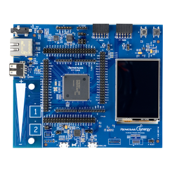
Promotion Kit S5D9 (PK-S5D9) 2. Getting Started 2. Getting Started To start working with the PK-S5D9, see the Quick Start Guide included in the kit. Figure 2.1 PK-S5D9 board close-up R12UM0009EU0101 Rev.1.01 Page 6 of 29 Apr 11, 2017 Arrow.com. Arrow.com. -
Page 7: Power Supply Requirements
MCU starts execution from internal flash (ROM). If J1 is in position 2-3, the MCU starts execution in USB program mode, which enables you to load a program directly to the internal MCU flash through the USB device interface using Renesas RFP software. Figure 3.1 shows the startup mode circuit for the CPU. Figure 3.1 CPU startup mode The J2 jumper can force the MCU to reset. - Page 8 Promotion Kit S5D9 (PK-S5D9) 3. Power Supply Requirements Figure 3.3 Measuring digital current consumption on the MCU Power consumption for the MCU analog supply requires removing resistor R114 and measuring current across it, as shown in Figure 3.4. Figure 3.4 Measuring analog current consumption on the MCU R12UM0009EU0101 Rev.1.01 Page 8 of 29 Apr 11, 2017...
-
Page 9: Board Components
Promotion Kit S5D9 (PK-S5D9) 4. Board Components 4. Board Components ® J-Link On-board Debugger ® The PK-S5D9 features a SEGGER J-Link on-board debugger, accessible through the J19 USB connector. Alternatively, the onboard debugger can be bypassed by removing resistors R107, R108, R109, and R110. Once removed, JTAG/SWD debugging can be done through the J18 header. - Page 10 Promotion Kit S5D9 (PK-S5D9) 4. Board Components Figure 4.2 LCD interface mode selection Touch-screen sensing uses a Semtech SX8656 resistive touch-screen controller, connected to the MCU through an I bus. Figure 4.3 shows the touch-screen controller connections. Figure 4.3 Touch-screen controller Ethernet The PK-S5D9 includes a Micrel KSZ8081 10/100 Ethernet physical interface.
-
Page 11: Usb Device Port
Promotion Kit S5D9 (PK-S5D9) 4. Board Components PMODB, available on the J14 connector, exposes a UART, three GPIO lines, and an interrupt line to the MCU. Figure 4.5 shows the PMODB interface connections. Figure 4.5 PMODB interface Both PMOD interfaces can output either 5V or 3.3V, depending on the position of the J13 and J15 jumpers. CAN, RS-232/485 The PK-S5D9 includes a UART interface (either RS-232 or RS-485) and a CAN interface. -
Page 12: Usb Host Port
Promotion Kit S5D9 (PK-S5D9) 4. Board Components detected since the power pin of this port is connected to the MCUs GPIO. Figure 4.7 shows the USB device port connections. Figure 4.7 USB device port USB Host Port The PK-S5D9 is equipped with a USB high-speed (480-Mbps) host port on J6. This host port can source a minimum current of 150 mA to devices connected to it. -
Page 13: User Buttons And Leds
Promotion Kit S5D9 (PK-S5D9) 4. Board Components Figure 4.9 Capacitive touch buttons and slider Audio The PK-S5D9 contains an amplified mono audio output on a standard 3.5 mm audio jack J16. The audio is generated with a D/A converter on output DA0, and the amplification gain can be changed by modifying resistor pairs R70/R71 and R73/R72. - Page 14 Promotion Kit S5D9 (PK-S5D9) 4. Board Components 4.11 QSPI Flash The PK-S5D9 includes a 64 Mb (8 MB) QSPI flash connected to the QSPI interface of the MCU. Figure 4.12 shows the connections for the QSPI flash. Figure 4.12 QSPI flash 4.12 Arduino Shield Interface The PK-S5D9 includes one Arduino Shield compatible interface, so that Arduino Shield boards can expand the PK-S5D9...
- Page 15 Promotion Kit S5D9 (PK-S5D9) 4. Board Components Figure 4.14 MCUs breakout headers R12UM0009EU0101 Rev.1.01 Page 15 of 29 Apr 11, 2017 Arrow.com. Arrow.com. Arrow.com. Arrow.com. Arrow.com. Arrow.com. Arrow.com. Arrow.com. Arrow.com. Arrow.com. Arrow.com. Arrow.com. Arrow.com. Arrow.com. Arrow.com. Downloaded from Downloaded from Downloaded from Downloaded from Downloaded from...
-
Page 16: Board Layout
Promotion Kit S5D9 (PK-S5D9) 5. Board Layout 5. Board Layout The PK-S5D9 board measures 145 mm x 120 mm. Figure 5.1 shows the location of all the relevant board components described in the prior section. Figure 5.1 PK-S5D9 component placement R12UM0009EU0101 Rev.1.01 Page 16 of 29 Apr 11, 2017... - Page 17 Promotion Kit S5D9 (PK-S5D9) 6. Configuration 6. Configuration The PK-S5D9 has several configuration options set by jumpers. Table 6.1 lists the different jumpers and their positions. Table 6.1 PK-S5D9 configuration jumpers Jumper Function MCU boot selection. If J1 is in position 1-2 (default), the MCU boots in normal mode (from its ROM). If J1 is set on the 2-3 position, the MCU boots in USB programming mode, which allows programming the MCU flash through the USB port.
- Page 18 Promotion Kit S5D9 (PK-S5D9) 7. Connectivity 7. Connectivity The following sections describe in detail the interfaces available on the PK-S5D9, including the MCU resources utilized in each. USB Host Port The PK-S5D9 includes a USB host/high-speed port (J6). This port supplies current to devices connected to it through a current limited power switch (U14).
- Page 19 Promotion Kit S5D9 (PK-S5D9) 7. Connectivity Table 7.3 Ethernet functions S5D9 Pin Function name P010 ETH_IRQ14# P806 ETH_RESET# P401 ETH_MDC P402 ETH_MDIO P705 ETH_CRS_DV P405 ETH_TXD_EN P700 ETH_TDX0 P406 ETH_TXD1 P702 ETH_RXD0 P703 ETH_RXD1 P704 ETH_RX_ER P701 ETH (reference clock) The PK-S5D9 includes a 240 x 320 QVGA LCD panel with touch-screen interface.
- Page 20 Promotion Kit S5D9 (PK-S5D9) 7. Connectivity Table 7.4 LCD functions (J3) S5D9 Pin Function name P610 LCD_RESET P314 LCD_VSYNC P313 LCD_HSYNC P900 LCD_CLK_B P315 LCD_Data_Enable P901 LCD_D15 P908 LCD_D14 P907 LCD_D13 P906 LCD_D12 P905 LCD_D11 P615 LCD_D10 PA08 LCD_D9 PA09 LCD_D8 PA10 LCD_D7...
- Page 21 Promotion Kit S5D9 (PK-S5D9) 7. Connectivity Table 7.6 PMODA port functions S5D9 Pin Function name P103 SSLA0_A P101 MOSIA_A P100 MISOA_A P102 RSPCK_A P111 IRQ4# P310 GPIO (PMOD pin 4) P311 GPIO (PMOD pin 6) P312 GPIO (PMOD pin 8) Table 7.7 PMODB port functions S5D9 Pin Function name...
- Page 22 Promotion Kit S5D9 (PK-S5D9) 7. Connectivity Table 7.9 UART interface functions S5D9 Pin Function name P706 UART_RXD P707 UART_TXD P801 INVALID P800 READY (RS-232) or RE (RS-485) Table 7.10 CAN interface functions S5D9 Pin Function name P203 CAN_TX P202 CAN_RX R12UM0009EU0101 Rev.1.01 Page 22 of 29 Apr 11, 2017...
- Page 23 Promotion Kit S5D9 (PK-S5D9) 8. Connections of Port and Connector 8. Connections of Port and Connector Table 8.1 shows port and peripheral functions of the MCUs and connections with PK-S5D9 connector. Table 8.1 Port and peripheral functions of the MCUs and connections with PK-S5D9 connector Port Peripheral Signal...
- Page 24 Promotion Kit S5D9 (PK-S5D9) 8. Connections of Port and Connector P309 Bluetooth BLE_RESET P310 PMODA J12 (4) P311 PMODA J12 (6) P312 PMODA J12 (8) P313 LCD_HSYNC J3 (40) P314 LCD_VSYNC J3 (41) P315 LCD_Data_Enable J3 (38) P400 PMODB IRQ0# J14 (2) P401 Ethernet...
- Page 25 Promotion Kit S5D9 (PK-S5D9) 8. Connections of Port and Connector P615 LCD_D10 J3 (31) P700 Ethernet ETH_TXD0 P701 Ethernet P702 Ethernet ETH_RXD0 P703 Ethernet ETH_RXD1 P704 Ethernet ETH_RX_ER P705 Ethernet ETH_CRS_DV P706 RS-232 UART_RXD J9 (4) P707 RS-232 UART_TXD J9 (3) P800 RS-232 READY/RE...
-
Page 26: Revision History
Revision History Description Rev. Date Page Summary 1.00 Feb 16, 2017 release 1.01 Apr 11, 2017 23-25 Description of pin connection and pin function corrected. All trademarks and registered trademarks are the property of their respective owners. Arrow.com. Arrow.com. Arrow.com. Arrow.com. - Page 27 Promotion Kit S5D9 (PK-S5D9) User’s Manual Publication Date: Rev.1.01 Apr 11, 2017 Published by: Renesas Electronics Corporation Arrow.com. Arrow.com. Arrow.com. Arrow.com. Arrow.com. Arrow.com. Arrow.com. Arrow.com. Arrow.com. Arrow.com. Arrow.com. Arrow.com. Arrow.com. Arrow.com. Arrow.com. Arrow.com. Arrow.com. Arrow.com. Arrow.com. Arrow.com. Arrow.com. Arrow.com. Arrow.com.
- Page 28 SALES OFFICES Refer to "http://www.renesas.com/" for the latest and detailed information. Renesas Electronics America Inc. 2801 Scott Boulevard Santa Clara, CA 95050-2549, U.S.A. Tel: +1-408-588-6000, Fax: +1-408-588-6130 Renesas Electronics Canada Limited 9251 Yonge Street, Suite 8309 Richmond Hill, Ontario Canada L4C 9T3...
- Page 29 Renesas Synergy™ Platform Promotion Kit S5D9 (PK-S5D9) R12UM0009EU0101 Arrow.com. Arrow.com. Arrow.com. Arrow.com. Arrow.com. Arrow.com. Arrow.com. Arrow.com. Arrow.com. Arrow.com. Arrow.com. Arrow.com. Arrow.com. Arrow.com. Arrow.com. Arrow.com. Arrow.com. Arrow.com. Arrow.com. Arrow.com. Arrow.com. Arrow.com. Arrow.com. Arrow.com. Arrow.com. Arrow.com. Arrow.com. Arrow.com. Arrow.com. Downloaded from Downloaded from...
Need help?
Do you have a question about the Synergy Promotion Kit S5D9 and is the answer not in the manual?
Questions and answers