Table of Contents
Advertisement
Advertisement
Table of Contents

Summary of Contents for K-TRON KCM
- Page 1 OPERATING AND MAINTENANCE INSTRUCTIONS Read this manual prior to opera- ting or servicing the equipment. This manual contains all safety labels and warnings. Original operating instructions 1090020601-EN Rev. 1.2.1 II 3D Ex tc IIIC T65°C 0590024903-D X 1190021904-A X...
- Page 2 If an error or ommission is found, please contact: documentation@ktron.com. Docu-No.: 1090020601-EN “K-Tron assumes no responsibility for damages resulting from misuse of any equipment or negligence on the part of operating personnel. Further, reference is made to the purchase order, acceptance or other document that con- Datum: 2012/Juli/09 tains the express K-Tron disclaimer of warranties for a statement of the provisions limiting or disclaiming certain warranties with respect to the Company's equipment.
-
Page 3: Table Of Contents
Warnings ........................... 21 Technical Data ........................ 22 Installation ........................28 Unpacking ......................... 28 Tools ..........................28 Dimensions KCM ......................29 Dimensions KCM SS ......................30 KCM-SS Hygiene mounting ....................30 Terminal descriptions ......................31 Docu-No.: 1090020601-EN Rev. 1.2.1 Page 3... - Page 4 4.10.19 AC interface analog I-O - J9 ..................... 45 4.11 I-O wiring connections ...................... 46 4.11.1 Safety input wiring to KCM Drive - J1 ................46 4.11.2 Drive enable input to KCM Drive - J1 ................46 4.11.3 Digital input #1 and #2 at Drive pc board ................47 4.11.4...
- Page 5 KCM CPU DIP switch setting .................... 57 5.1.3 KCM addressing with CPU DIP switch positions 1-5 ............57 5.1.4 K-Port 1 function via KCM CPU DIP switch positions 6-8 ..........57 5.1.5 K-PROM configuration ...................... 58 5.1.6 Display backlight control ....................58 5.1.7...
- Page 6 Emergency stop procedure ....................72 Switching ON and OFF ..................... 72 Cleaning ........................... 73 Maintenance ........................74 9.0.1 Required skills/training for maintenance of the KCM ............74 9.0.2 General tools required ...................... 74 Preventive maintenance ....................74 Parameter Backup ......................75 KCM fuse replacement .....................
- Page 7 KCM to BM-85 Host port wiring ..................108 12.4.10 450 watt DC drive wiring example - 0000007405 ............109 12.4.11 KCM without SIB board - dc motor - 0000002610 ............110 12.4.12 Remote KCM with SIB pcb at feeder ................111 12.4.13 Field wound DC motor wiring example ................
- Page 8 Page 8 Docu-No.: 1090020601-EN Rev. 1.2.1...
-
Page 9: Safety Notes
Safety Notes Safety symbols definitions 1.1 Safety Notes ▲ The explosion-proof control is one of the products with increased risk of damage, as it is used in hazardous locations. For handling with this device is therefore an increased duty of care. The front cover is part of the ignition protection and should not be opened in an explosive atmosphere. -
Page 10: Electrical Hazard Icon
Safety Notes 1.2 Operator responsibilities 1.1.1 Electrical Hazard Icon This sign indicates an electrical hazard. It is located on covers and doors. Only qualified personnel are allowed to remove these covers or open the doors. 1.1.2 Ground Icon This sign indicates that a ground/PE connection is required. 1.1.3 ATEX Icon Important information to explosion protection. -
Page 11: Proper Use
▲ The operation of the device in hazardous areas is only allowed in areas with classification zone 22. ▲ Only operate the device in conjunction with the feeder equipment from K-Tron. ▲ Only operate the device in accordance with the specified technical data. -
Page 12: Safety Devices
▲ Have repairs to the equipment carried out by – your authorized K-Tron customer service center – qualified personnel, trained by K-Tron. ▲ Only use original K-Tron parts for repairs. ▲ In EX equipment may only manufacturer-approved batteries used. Replacement from the battery, see section 9.4. -
Page 13: Removal From Service
Safety Notes Removal from service 1.11 1.11 Removal from service ▲ The operator is responsible for the proper removal and disposal of the equipment from service. Docu-No.: 1090020601-EN Rev. 1.2.1 Page 13... -
Page 14: Assembly And Function
KCM XPC3 stands for K-TRON Control Module and XPC3 for Explosion-protection of Category 3. The KCM is a control and a drive module for K-Tron feeders. The KCM is normally mounted directly on the feeder. It can also be mounted remotely.The KCM can used as controller for feeding processes which... -
Page 15: Zones And Device Categories (Dust)
Field of application 2.1 2.1.3 Zones and device categories (dust) Zone Description Use of KCM Zone 20 An area in which a dangerous, explo- sive atmosphere in the form of a cloud of flammable dust suspended in the air Not allowed is either constantly present, or frequent- ly or for long periods at a time. -
Page 16: Abbreviations
• KSL = K-Tron line interface for up to 8 feeders • K-Net = KCM serial data connection to KSU-II, KSL, K-Vision or • K-Port 1 and K-Port 2 = data ports for a K-Tron specific interface • KSU-II = Single unit user interface for the KCM •... -
Page 17: Additional Programming Information
• PID programming • SFM programming • VOL programming • LWB programming • WBB programming • SFB programming • GWB programming • The K-Tron’s supplied operating instructions describe how to use the connected feeder. Docu-No.: 1090020601-EN Rev. 1.2.1 Page 17... -
Page 18: Overview
K-Vision for up to 16 feeders and a KSC for interface for up to 30 feeders. The KCM is comprised primarily of a cpu pc board, and a drive pc board. Drive choices include a 1600 watt DC drive, a 450 watt DC... -
Page 19: Structure
Assembly and Function Structure 2.3 Structure The KCM includes the following components, some which are optional. 2.3.1 Enclosure First, the pc board assemblies are housed in an Aluminium profile or stainless steel housing with a swing-out cast cover. The enclosure is designed to mount directly to a feeder or be located in a control panel. -
Page 20: Circuit Assemblies
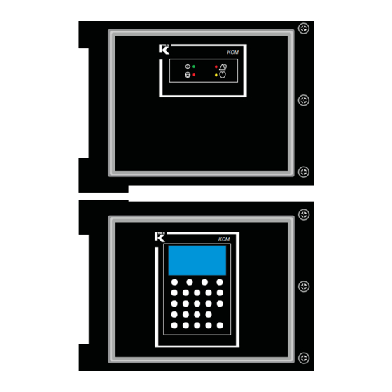
There are two choices for the on-board KCM operational display. First, a fully functional display and keypad assembly may be mounted to the rear of the KCM cpu pc board and permit access via the front of the cover for all operational actions. -
Page 21: Safety Devices And Warnings
2.4.2 Warnings On the front panel of the KCM, either with the full keypad or LED display, the following safety messages are supplied. Fig. 2.4 KCM safety label Make all ground/PE connections to these points as indicated. -
Page 22: Technical Data
See declaration of conformity II 3D Ex tc IIIC T65°C IP65 (only ATEX devices) -20 to +40°C 1190021904-A X Service application KCM must only be installed in an industrial or manufacturing power environment. Connection residential power system is not permitted. - Page 23 Technical Data Safety devices and warnings 2.4 Specification Limitations Notations Maximum input power DC motor-1600 watt drive: 2.0 KVA at 230 Vac 1.2 KVA at 115 Vac DC motor-450 watt drive: 0.5 KVA at 230 Vac 0.5 KVA at 115 Vac Vibratory drive: 250 VA at 115/230 Vac Stepper drive-0000005987:...
- Page 24 Pulsing DC at 2A. For dc motor drive. Special option 0000000639. standard 162 Vp DC at 115 Vac KCM. 325 Vp DC at 230 Vac Maximum dc motor 2500 rpm at 125% drive command Maximum input frequency from the speed motor tachometer cannot exceed 10 kHz.
- Page 25 +5VDC. Maximum motor speed is motor dependent. Speed accuracy-stepper ±0.01 rpm drive Maximum current from 500 mA maximum, all Process 24 Sourced from KCM internal power 24 VDC VDC connections supplies. Communications interface Internal data comm. 9 bit proprietary connections-six permitted.
- Page 26 Specification Limitations Notations Analog input rating Input value selected by jumpers on 0-20 mA/4-20 mA with 100 the KCM CPU circuit card. impedance or 0-5 Vdc with 94.5 k impedance or 0-10 Vdc with 65.3 k impedance...
- Page 27 0.05G, 10 to 50 Hz, all directions MTBF/MTTR > 45000 hours/< 15 minutes Approvals Met labs to UL 61010-1 CSA-Canada CE-Europe Label KCM (only ATEX devices) Label KCM SS (only ATEX devices) Table page 6 of 6 Docu-No.: 1090020601-EN Rev. 1.2.1 Page 27...
-
Page 28: Installation
4.1 Unpacking Installation ▲ Protect the explosion-proof control from direct sunlight. ▲ Ensure that the KCM is connected and put into operation only by authorized personnel. ▲ KCM mounting must be vertical and protect from direct sunlight.. ▲ Minimum lateral mounting spacing between KCMs is 25 mm. -
Page 29: Dimensions Kcm
Fig. 4.1 Dimensions - in mm Notes: • Slot A holds a M6 hex head bolt. • Use 8 bolts per KCM for secure mounting. • Cable gland hole sizes are: – 12 x M16x1.5 mm – 4 x M20x1.5 mm Docu-No.: 1090020601-EN Rev. -
Page 30: Dimensions Kcm Ss
Installation 4.4 Dimensions KCM SS Dimensions KCM SS 295.3 (11.63) 157.7 (6.21) 92.6 Fig. 4.2 Dimensions - in mm KCM-SS Hygiene mounting A specially designed controller mounting is available to improve the cleaning capacity for hygienic applications. In this mounting, the cable... -
Page 31: Terminal Descriptions
6 5 4 3 2 1 6 5 4 3 2 1 6 5 4 3 2 1 Fig. 4.5 KCM cpu keying diagram 1 2 3 4 5 6 1 2 3 4 5 6 Fig. 4.6 K-Port keying diagram Docu-No.: 1090020601-EN Rev. -
Page 32: Cpu Connection Summary
Installation 4.7 CPU connection summary CPU connection summary See programming manuals for configuration of I-O. 4.7.1 CPU DB-9 Configuration port - P1 Terminal Function Notes P1-2 To PC, serial port, pin 3 P1-3 To PC, serial port, pin 2 P1-5 Common To PC, serial port, pin 5 4.7.2... -
Page 33: Internal Channel; Cpu To Drive - J11
Installation CPU connection summary 4.7 4.7.4 Internal channel; CPU to Drive - J11 Terminal Function Notes J11-1 Power + 24Vdc power from Drive power supply J11-2 Common Ground/common from Drive power supply J11-3 RxD+ Internal data channel to Drive J11-4 RxD- Internal data channel to Drive J11-5... -
Page 34: K-Port Connection Summary
▲ Based upon the KCM power budget, only one KSU-II can be powered from the KCM. ▲ If a second KSU-II is connected to a KCM, use a separate 24 Vdc power supply for that KSU-II. ▲ For host connections, see the appropriate communication adapter card manual ▲... -
Page 35: K-Port Details
K-Port details Each K-Port supports RS485 (4 wire and 2 wire). K-Port 1 is used for KSC, K-Vision and KSU-II to KCM connections. K-Port 2 is used for KCM to remote Modbus I-O and KSU-II to KCM connections. 4.8.4 K-Port 1 connections - J14... -
Page 36: Host Port Connections
Installation 4.9 Host port connections Host port connections For the host port protocols of Modbus TCP, Ethernet IP, DeviceNet, ModbusPlus, ProfibusDP, Profinet, please refer to the following man- uals for wiring details. Protocol Document Number DeviceNet 0590020609 Ethernet IP Modbus TCP 0590020610 Profinet ModbusPlus... -
Page 37: Drive Connection Summary
Installation Drive connection summary 4.10 4.10 Drive connection summary The first group of connections, tables 4.10.1 4.10.4 are common for all drive types. See programming manuals for application information. 4.10.1 Drive digital inputs- J1 Input #1/#2 functions are programmable. Terminal Function Notes J1-1... -
Page 38: Drive Internal Channel; Drive To Cpu - J3
Installation 4.10Drive connection summary 4.10.2 Drive Internal Channel; Drive to CPU - J3 Terminal Function Notes J3-1 Power + 24 Vdc power from Drive power supply J3-2 Common Common from Drive power supply J3-3 TxD+ Internal data channel to CPU J3-4 TxD- Internal data channel to CPU... -
Page 39: Drive Output Relays - J5
Installation Drive connection summary 4.10 4.10.4 Drive output relays - J5 • Relay functions are programmable. – Contact ratings: 250 Vac, 30 Vdc, 5 A, maximum Terminal Function J5-1 Relay #1, common J5-2 Relay #1, N.O. J5-3 Relay #1, N.C. J5-4 Relay #2, common J5-5... -
Page 40: Dc Motor Drive Power - J6
4.10.8 Change DC motor shaft rotation To change the shaft rotation, switch the polarity of the motor armature leads either at the KCM DC Drive or at the motor. Do this only with power removed from the KCM. Page 40... -
Page 41: Stepper Drive Specific Connections
Installation Drive connection summary 4.10 4.10.9 Stepper drive specific connections ▲ Two stepper drive wiring configurations for J6 are used. The Universal Stepper drive, 0000005987 is described in table 4.10.10. The LoPo and HiPo stepper drives, 0000001430 and 0000004568 are described in table 4.10.11 4.10.10 Universal stepper motor drive power - J6 Terminal... -
Page 42: 4.10.12 Stepper Motor Drive Feedback - J2
Installation 4.10Drive connection summary 4.10.12 Stepper motor drive feedback - J2 Terminal Function Notes J2-1 + 5 Vdc + 5 Vdc power at 100 mA for sensor power J2-2 Input channel A from velocity sensor. Also used if the sensor has Frequency In A only a single output. -
Page 43: 4.10.14 Vibratory Drive Power - J6
Installation Drive connection summary 4.10 4.10.14 Vibratory drive power - J6 Terminal Function Notes J6-1 Variable amplitude and frequency power to vibratory feeder Vibratory feeder coil (-) drive coil. J6-2 Variable amplitude and frequency power to vibratory feeder Vibratory feeder coil (+) drive coil. -
Page 44: 4.10.17 Ac Interface Drive Power - J6
Installation 4.10Drive connection summary 4.10.17 AC interface drive power - J6 Terminal Function Notes J6-1 Switched line power L2 to Fused and switched through relay K6 from the input line remote motor contactor power at J6-7. J6-2 Switched line power L1 to Fused and switched through relay K6 from the input line remote motor contactor power at J6-8. -
Page 45: 4.10.19 Ac Interface Analog I-O - J9
Installation Drive connection summary 4.10 4.10.19 AC interface analog I-O - J9 Terminal Function Notes J9-1 For drive command control to external drive at 500 mA dc Analog current output (+) maximum source. J9-2 Analog current output (-) For drive command control to external drive. J9-3 For drive command control to external drive. -
Page 46: I-O Wiring Connections
Notes: • The maximum voltage drop across the contacts is 2.0 Vdc. Drive – J1 • The Drive Enable Input must be at 24 Vdc to permit KCM drive output. Close to • The input signal as shown in optically isolated from the KCM. -
Page 47: Digital Input #1 And #2 At Drive Pc Board
Installation I-O wiring connections 4.11 4.11.3 Digital input #1 and #2 at Drive pc board Notes: • These two digital inputs are found on the Drive pcb at terminal J1. 5 Vdc 24 Vdc • These two inputs on the drive circuit board have the possibility to be wired for either pull-up or pull down applications. -
Page 48: Ac Interface Drive Output Relay K4 - J9
Installation 4.11I-O wiring connections 4.11.5 AC interface drive output relay K4 - J9 • K4 is relay that provides a run enable control signal to an external device on the AC Interface drive circuit card. When the contacts are closed, the AC interface is permitting an external device to run, if that device’s interlock is wired to this relay. -
Page 49: Kcm Cpu Digital Outputs - J8
Installation I-O wiring connections 4.11 4.11.8 KCM CPU digital outputs - J8 This is an example of one of four programmable digital outputs available from the KCM CPU pc board. This example is driving a relay-CR. CPUout1=J8-6 CPUout2=J8-7 Notes: CPUout3=J8-8 CPUout4=J8-9 •... -
Page 50: 4.11.10 Kcm Cpu Analog Output - J9
Installation 4.11I-O wiring connections 4.11.10 KCM CPU analog output - J9 This circuit shows the analog output (0-20mA/4-20mA) that is available from the CPU pcb at terminal J9. CPU-J9 The output function is programmed via the I-O menu, Analog Output Analog Out (+) sub-menu. -
Page 51: 4.11.12 Kcm Cpu Frequency Input - J9
Installation I-O wiring connections 4.11 4.11.12 KCM CPU frequency input - J9 This circuit shows the frequency input that is available at the CPU pcb at terminal J9. CPU-J9 The input function is programmed via the I-O menu, Setpoint Input J9-1 2.2k... -
Page 52: Connecting The Kcm
• Electrical connection diagram examples are found in the Appendix. • If the KCM SS used in conjunction with the Hygiene mounting must be read the instructions in section 4.5. Page 52... -
Page 53: Recommended Wire Sizes And Maximum Lengths
16 AWG, 500 m (shielded) K-Port Minimum: 0.5 mm or 24 AWG, 500 m (shielded) Maximum: 1.3 mm or 16 AWG, 100 meters DC Power to KSU-II from KCM Minimum: 0.5 mm or 24 AWG, 20 meters Docu-No.: 1090020601-EN Rev. 1.2.1 Page 53... -
Page 54: Power Wiring; Specific Requirements
4.13 Power wiring; specific requirements Use this section as a guideline for power wiring installation. ▲ Each KCM must have its own power mains disconnect or circuit breaker. ▲ The disconnecting means or circuit breaker must be in close proximity to the equipment and within easy reach of the operator. -
Page 55: Shielding And Cable Glands
0.1 ohm) via the cable glands on both sides. Lay the shielding (1) evenly over the O-ring (2). If the KCM SS used in conjunction with the Hygiene mounting must be read the instructions in section 4.5. Fig. 4.19 Cable gland shielding Docu-No.: 1090020601-EN Rev. -
Page 56: Kcm Set-Up
KCM Set-Up 5.1 Initial set-up for KCM CPU KCM Set-Up Initial set-up for KCM CPU ▲ Do not open the KCM unless power has been removed and no explosive atmosphere is present. 5.1.1 CPU pc board jumper settings • JP2 through JP4 selects the range for an analog input. -
Page 57: Kcm Cpu Dip Switch Setting
Initial set-up for KCM CPU 5.1 5.1.2 KCM CPU DIP switch setting Positions 1-5 set the address of the KCM on the K-Net. Positions 6-8 control the function of the K-Port channel #1. ▲ Off = <0>, On = <1> for each switch position 5.1.3... -
Page 58: K-Prom Configuration
The K-PROM stores the actual data only on power shutdown not on CPU reset. The K-PROM must be installed on the KCM CPU pc board and it will be loaded by the Config port connection for communications or via the user interface for operations. -
Page 59: Initial Set-Up For Kcm Drives
Stepper drive. 5.2.1 Drive jumper settings-all drive types listed These settings must be made for all KCM drives. See below. Notes: • Digital input #1 or #2 must be set <True-On-1> to perform the programmed function •... -
Page 60: Dc Drive Set-Up
KCM Set-Up 5.3 DC drive set-up DC drive set-up 5.3.1 DC drive selection notes: • The 450 W dc drive provides a max at 2.50 Amps out. For 100 V motors this corresponds to a max nameplate power of 240 W. For 200 V motors this corresponds to a max nameplate of 500 W. -
Page 61: 450/1600 Watt Dc Drive Pc Board Dip Switch Settings
011 = 3 ..111 = 7 Not used 5.3.4 Additional jumper settings for 450 watt drive Normal Function Position [1-2] - SLM/KCM control JP-4 [2-3] - K10S protocol Position [1-2] is normal [1-2] - SLM/KCM control JP-5 [2-3] - K10S protocol Position [1-2] is normal Docu-No.: 1090020601-EN Rev. -
Page 62: Ac Drive Set-Up
AC drive interface pc board DIP switch settings Action Switch Range Off = 0-20 mA Analog Output On = 4-20 mA Off = KCM programmable Function of MDU Input 2 On = MDU alarm input Output frequency (34) 00 = 10 kHz, 10 = 15 kHz,... -
Page 63: Stepper Drive Set-Up (All Types)
KCM Set-Up Stepper drive set-up (all types) 5.5 Stepper drive set-up (all types) 5.5.1 Stepper motor programming table Feeder Type Maximum Required Stepper Drive Motor Power Setting-W 0000001430 BSP100 0000005987 0000004568 (194 watts) BSP125 49 or 194 0000001430 (49 watts) -
Page 64: Vibratory Drive Set-Up
KCM Set-Up 5.6 Vibratory drive set-up Vibratory drive set-up For loss-in-weight feeding or loss-in-weight batching only. 5.6.1 Vibratory drive pc board DIP switch settings Action Switch Pos Range Drive address (1-7) 1, 2, 3 (123) 000 = 0, 001 = 1, 010 = 2, 011 = 3 ..111 = 7... - Page 65 KCM Set-Up Vibratory drive set-up 5.6 1. Switch the feeder to <Volumetric> mode. 2. Start the feeder. 3. Read displacement from label on vibratory drive. 4. Calculate <Vib Span> according to the following formula. Vibratory span formula: New <Vib Span> = (Displayed Vib Span)* (expected displacement/Actual displacement.)
-
Page 66: Gwb Application Drive Set-Up
The weight information from the scale is used to control the feeders. 5.7.1 GWB Hardware overview Each ingredient feeder requires a KCM Drive board. All KCM Drive boards are usable: – 450 watt DC motor drive – 1600 watt DC motor drive –... -
Page 67: Setup Dc Drive Boards
KCM Set-Up GWB Application drive set-up 5.7 • The KCM stepper and the AC interface boards can only have address 1 to 4 so no it is not possible to use these units for feeder 5 .. 8 • Addressing the Motor Drive Boards using their DIP switches. -
Page 68: Setup Stepper Drive Boards
KCM Set-Up 5.7 GWB Application drive set-up Ingredient Address 5.7.4 Setup Stepper Drive Boards The Stepper bd. has a 4 position DIP switch and due to needing two other hardware flags, there are only two DIP switches used for setting the address of the board as shown below. -
Page 69: Transportation, Storage, Disposal
KCM as received. Notes on storage To store the KCM, secure unit in the anti-static packing materials. The storage location must be clean and dry and not exceed the rated storage temperature limits as stated. -
Page 70: Operation
Operation 7.1 Initial operation Operation ▲ Do not open the KCM unless power has been removed and no explosive atmosphere is present. ▲ Allow 3 minutes for power to dissipate prior to opening the enclosure. ▲ Do not operate machinery unless all guards are in place and all safety checks have been made. -
Page 71: Kcm-Sd Led Status Display
The alarm relay will activate if programmed. HEARTBEAT LED Blinks as the KCM CPU is running. When using the KCM with a display and keypad mounted to its surface (KCM-KD), refer to the operating manual for operational information. Docu-No.: 1090020601-EN Rev. 1.2.1... -
Page 72: Emergency Stop Procedure
7.2 Emergency stop procedure Emergency stop procedure • Each KCM must have a main switch to supply its main power. • The main switch should be within easy reach of the operator To shutdown the KCM quickly, switch off the appropriate main switch. -
Page 73: Cleaning
To clean externally, use a damp cloth to remove debris using normal industrial cleaners. Only clean the external portions of the KCM with its enclosure fully closed. Only use cleaners at meet the following specifications. -
Page 74: Maintenance
▲ If the KCM SS used in conjunction with the Hygiene mounting must be read the instructions in section 4.5. ▲ During operation and immediately after shut-down, the capacitors and, therefore, the printed circuit boards of the KCM are under high voltage. -
Page 75: Parameter Backup
▲ Do not replace any fuse while under power. ▲ Wait 3 minutes after disconnecting KCM power prior to opening the case. Notes: • Some fuses are self-resetting and require no replacement. -
Page 76: List Of Auto Resetting Fuses
• 1600 watt DC motor drive: – F3: Failure will cause power loss of 24 Vdc at the I-O. – F4/F5: Failure will cause power loss to the KCM CPU. • 450 watt DC motor drive – F3: Failure will cause power loss of 24 Vdc at the I-O. -
Page 77: 1600 Watt Dc Motor Drive Fuse Location-0000002610
Maintenance KCM fuse replacement 9.3 9.3.5 1600 watt dc motor drive fuse location-0000002610 Following fuses are (5x20 mm, slow-blow) used: F1/F2 -12.5AT, 5x20 mm, 250Vac fuse. SPDT Fig. 9.1 Fuse location, 1600 W DC motor drive 9.3.6 450 watt dc motor drive fuse location-0000007405 Following fuses are (5x20 mm, slow-blow) used: F1/F2-6.3AT, 5x20 mm, 250Vac fuse. -
Page 78: Ac Motor Drive Interface Fuse Location-000003413
Maintenance 9.3 KCM fuse replacement 9.3.8 AC motor drive interface fuse location-000003413 Following fuses are (5x20 mm, slow-blow) used: F1/F2-6.3AT, 5x20 mm, 250Vac fuse. SPDT Fig. 9.4 Fuse location, AC interface 9.3.9 Stepper drive interface fuse location-0000005987 Following fuses are (5x20 mm, slow-blow) used: F4-2.0AT, 5x20 mm, 250Vac fuse. -
Page 79: Battery Replacement
• Replace battery only with the same or recommended equivalent type. • Dispose of used battery according as required by law. 1. Switch off power to the KCM. 2. Wait for three minutes prior to opening KCM cover. 3. Open KCM. 4. Replace battery BT1. 5. Re-install cover. -
Page 80: Kcm Service Connections
KCM service connections The Config data ports are service connections to the KCM. Service connection to the KCM is possible by the USB port (J13) or the RS- 232 port (P1). A PC with K-Tron applications such as Loader, SmartConfig and ParamStore are used with the KCM to upload new application programs, upload custom <KGR>... -
Page 81: Troubleshooting
10.1 General information on fault detection ▲ Immediately after shut-down, the capacitors and, therefore, the conducting parts of the KCM are under high voltage. For this reason, before opening the KCM: • Disconnect the KCM from the power supply; • Wait the prescribed time of 3 minutes. -
Page 82: Kcm Cpu Leds
10.2KCM CPU LEDs 10.2 KCM CPU LEDs ▲ It is dangerous to open the KCM cover without removing power as high voltage is present on the Drive printed circuit board. Use the internal LEDs to evaluate KCM function. A listing is provided to help diagnose problems. -
Page 83: Cpu Pc Board Leds
Data is being received from the drive pc board on the channel Internal data channel. CPU is the channel master. Alarm Alarm function KCM pc board has an alarm condition 10.2.2 K-Port LEDs Refer to Fig. 10.1 for locations on cpu pcb near location J14/J15. -
Page 84: Kcm Drive And Power Supply Details
10 Troubleshooting 10.3KCM Drive and Power Supply Details 10.3 KCM Drive and Power Supply Details There are a series of drive circuit boards used for a variety of drive application. A listing is below. Note: • The 0000005987 stepper drive replaces both the LoPo and HiPo stepper drive when available. -
Page 85: Kcm Drive Pc Board Leds-All Types
Connect an external current/power measuring device only to the AC + 5 Vdc current input of the KCM, as the control of the motor takes place via Blue pulse width modulation and the current to the motor cannot be mea- Yellow sured using conventional instruments. -
Page 86: Dc Motor Drive Problems And Solutions
Check signal, if pick-up is OK, and • If scale interface pc board (SIB) is used, the SIB has failed. SIB is used, replace SIB. If signals are OK, replace KCM. • Setpoint is too high. Reduce setpoint. Check programming. -
Page 87: Vibratory Drive Problems And Solutions
Check that KCM has power. Check signal, replace sensor. Tray runs at • Displacement sensor has failed. maximum If signals are OK, replace KCM. • Setpoint is too high. displacement. Reduce setpoint. Check programming. Tray displacement •... -
Page 88: Stepper Drive Problems And Solutions
Check for alarms that might stop the machine. Check display status for <Wait>, <Disa>, <Alsh>. Check that KCM has power. Check motor cable and motor. Motor does not run. • Motor cable fault. Alarm LED is <On>. -
Page 89: Stepper Alarm Led Flash Sequence
Alarms 1, 2, 4, 6, 7, 8, 9 are cleared by the Alarm Clear message from the KCM CPU. Alarm 5 is cleared only by the Stop command from the KCM CPU. -
Page 90: Ac Interface Drive Problems And Solutions
Check signal, if pick-up is OK, and • If scale interface pc board (SIB) is used, the SIB has failed. SIB is used, replace SIB. If signals are OK, replace KCM. • Setpoint is too high. Reduce setpoint. Check programming. -
Page 91: Optional Devices
11.1 Host communication circuit cards These circuit cards plug into the Host slot on the KCM CPU circuit card. The host port is configured via the KSU-II SYSTEM menu or via the PC connected to the Config port on the KCM. -
Page 92: Field Power Supply
Field power supply In some select applications, a field wound DC motor is used. In that instance, a KCM DC Field Supply is used. (part number 0000000639) It is mounted near the motor. It is supplied with line power and the supply will output DC field power. -
Page 93: Sft Expander Circuit Card
Daisy chain connector The daisy chain connector permits easy cabling of K-Net connections from one KCM to another without having to have 2 wires in any terminal. point. This connector plugs into either K-Port 1 or K-Port 2. Fig. 11.4 Daisy chain connector Docu-No.: 1090020601-EN Rev. -
Page 94: Appendix
12 Appendix 12.1Cable length specifications Appendix 12.1 Cable length specifications 12.1.1 DC motor cable lengths: 230 Vac Motor Type Voltage Current Cable length for a Cable length for a Rating Rating diameter of 1.5 mm diameter of 4 mm 16 AWG, in meters 12 AWG, in meters Lenze 55 W 180V... -
Page 95: Cable Lengths For Speed Feedback Signals
Notes: • The Scale Interface pc board (SIB) pc board is located in a junction box on the side of the feeder and is used when the KCM is not mounted on the feeder. • The cable must be fully shielded. -
Page 96: Kcm I/O Defaults
12.2KCM I/O defaults 12.2 KCM I/O defaults The following table shows the standard bit I/O assignment. If other function are needed reassignment is possible with the operating unit. 12.2.1 Default KCM Programmable I-O table. In/output Location LWF/LWB PID/VOL CPU Input 1... -
Page 97: I-O Function Selection
Appendix 12 KCM I/O defaults 12.2 12.2.2 I-O function selection Following the possible selection on the KSU-II operator interface for the I/O assignment. Open I/O menu and select the desired sub- menus. Abbreviations: • CONT = LWF, WBF, PID, VOL and SFM control (continuous) •... - Page 98 12 Appendix 12.2KCM I/O defaults Digital output Digital input None Start Stop None Interlock Run Enable Any Alarm ALS Input Alr Relay Ack Alarm ALS Out Clr Alarm Drive Ena Start/Stop All (Not VOL/XTR) Grav Mode All (Not VOL/XTR) VOL Mode Auto Mode MAN Mode PSR Map...
-
Page 99: I-O Function And Kcm State Indications
• {blank} - If no status is displayed, the controller had a STOP command and all other conditions are cleared. Notes: • A START and STOP command can be issued from the K-Tron operator interface, Digital Input, or host communications. • Run Enable, Drive Enable, and Alarm Shutdown inputs issue a STOP command when activated. - Page 100 • If the host communications is reading the CondensedProcStatus, the KCM state can be determined from the following bits in the status word. Assuming the word starts at bit 0, bits 2 and 3 would help identify the state.
-
Page 101: Kcm Wiring Examples
J14 / J15 Fig. 12.1 KCM to KSU-II wiring example • If the KSU-II is more than 10 meters from the KCM, KSU-II power must be supplied from an independent power supply. • Either K-Port #1 or #2 may be used. -
Page 102: Kcm To Ksl Wiring At K-Port 1
12 Appendix 12.4KCM wiring examples 12.4.3 KCM to KSL wiring at K-Port 1 • K-Port #1 is to be used only. KSL-DB-9-RS485 K-Port 1 KCM K-Port KSL DB-9 Fig. 12.2 KCM to KSL wiring Page 102 Docu-No.: 1090020601-EN Rev. 1.2.1... -
Page 103: Kcm To Ksc Wiring At K-Port 1- Digi Card
• The wiring may be different for other RS485 serial communication cards. • K-Port #1 is to be used only. Digi RS485 Serial KSC-DB-9-RS485 K-Port 1 KCM K-Port KSC DB-9 Fig. 12.3 KCM to KSC wiring with Digi RS485 serial port Docu-No.: 1090020601-EN Rev. 1.2.1 Page 103... -
Page 104: Kcm To Ksc Wiring At K-Port 1- Moxa Card
• The wiring may be different for other RS485 serial communication cards. • K-Port #1 is to be used only. Moxa RS485 Serial KSC-DB-9-RS485 K-Port 1 KCM K-Port KSC DB-9 Fig. 12.4 KCM to KSC wiring with Moxa RS485 serial port Page 104 Docu-No.: 1090020601-EN Rev. 1.2.1... -
Page 105: Kcm To Ksc Wiring At K-Port 1- K-Tron Converter
• The wiring may be different for other RS485 serial communication cards. • K-Port #1 is to be used only. 9191-700550 RS 232 to RS422 Converter DB-9-RS422 K-Port 1 KCM K-Port Converter DB-9 Fig. 12.5 KCM to KSC wiring with interface 9191-700550 serial converter Docu-No.: 1090020601-EN Rev. 1.2.1 Page 105... -
Page 106: Kcm To Wago I-O Wiring At K-Port 2
KCM to WAGO I-O wiring at K-Port 2 • Refer to WAGO manual 750-138 for more information • Only K-Port #2 is used • WAGO bus coupler must be configured to function with the KCM WAGO-DB-9-RS485 K-Port 2 KCM K-Port WAGO DB-9 Fig. -
Page 107: Kcm To Kf2 Host Port Wiring
KCM wiring examples 12.4 12.4.8 KCM to KF2 Host port wiring This example shows the comm circuit card in the Host slot on the KCM CPU circuit card. The AB KF2 module is wired to J1 connector. AB KF2 Module... -
Page 108: Kcm To Bm-85 Host Port Wiring
12 Appendix 12.4KCM wiring examples 12.4.9 KCM to BM-85 Host port wiring This example shows the comm circuit card in the Host slot on the KCM CPU circuit card. The Modicon BM-85 multiplexer module is wired to J1 connector. Modicon BM-85... -
Page 109: Watt Dc Drive Wiring Example - 0000007405
Appendix 12 KCM wiring examples 12.4 12.4.10 450 watt DC drive wiring example - 0000007405 • Not all terminal blocks are shown in this example. +5Vdc 1 2 3 4 5 6 Speed Sensor Safety Drive Enable Vac line in... -
Page 110: Kcm Without Sib Board - Dc Motor - 0000002610
8 7 6 5 4 3 2 1 12 11 10 9 8 7 6 5 4 3 2 1 PE Mtr Drive Enable Safety DC Motor Vac line in Fig. 12.10Feeder mounted KCM wiring example - 1600 W DC Drive Page 110 Docu-No.: 1090020601-EN Rev. 1.2.1... -
Page 111: 12.4.12 Remote Kcm With Sib Pcb At Feeder
Appendix 12 KCM wiring examples 12.4 12.4.12 Remote KCM with SIB pcb at feeder This is a feeder wiring example for a remote KCM with a feeder mounted SIB circuit card for differential speed signal interfacing. (Fig. 12.11 Fig. 12.12) The speed encoder interface is shown mounted to J2 in this example. - Page 112 Spd 2 In - Fig. 12.12Differential input for DC motor drives wiring-Encoder Interface ▲ The Encoder Interface pcb functions with all drives except the AC interface drive when used to connect the KCM to the feeder mounted scale interface pcb. Page 112...
-
Page 113: 12.4.13 Field Wound Dc Motor Wiring Example
Appendix 12 KCM wiring examples 12.4 12.4.13 Field wound DC motor wiring example ▲ Danger of voltage Removal of JP3 and JP4 removes the discharge resistor R2 from the circuit. If no motor is connected, caution must be observed to... -
Page 114: 12.4.14 Stepper Drive Wiring Example For 0000005987
12 Appendix 12.4KCM wiring examples 12.4.14 Stepper drive wiring example for 0000005987 • Not all terminal blocks are shown in this example. • In the example shown the encoder and motor signals in the same cable. This requires individually shield twisted pair with the signals groups as shown and an overall shield. -
Page 115: Encoder Line Driver Board
Appendix 12 KCM wiring examples 12.4 12.4.15 Encoder Line Driver Board • For cable length > 2 m the Encoder Line Driver Board 0000020276 is installed at the stepper motor. +5VDC +5VDC +5VDC +5VDC INDEX INDEX COMMON COMMON CON5 CON5... -
Page 116: Vibratory Feeder Wiring Example - 0000000684
12 Appendix 12.4KCM wiring examples 12.4.16 Vibratory feeder wiring example - 0000000684 • Not all terminal blocks are shown in this example. Gray Vibratory Drive Pink Green Yellow White Brown 6 5 4 3 2 1 6 5 4 3 2 1 DPDT 6 5 4 3 2 1 12 11 10 9 8 7 6 5 4 3 2 1... -
Page 117: Ac Drive Wiring Example - 0000003413
Appendix 12 KCM wiring examples 12.4 12.4.17 AC drive wiring example - 0000003413 • Not all terminal blocks are shown in this example. • There are a number of ways to wire the AC drive. The example above shows an NPN tachometer (current sinking) input as a frequency source and a current output to the remote variable frequency AC drive. -
Page 118: 12.4.18 Kcm Interlock Wiring Example
KCM #2-J8 KCM #3-J8 Fig. 12.18KCM interlock wiring for ALS KCM programming example for ALS interlock wiring: • CPU digital input #3 programmed for <ALS Input> • CPU digital output #3 programmed for <ALS Out> • Terminal 10 is common •... -
Page 119: 12.4.19 Hi/Lo Auto Gear External Switching Circuit
KCM wiring examples 12.4 12.4.19 Hi/Lo Auto gear external switching circuit The following diagram shows how to safely wire the KCM for automatic gear switching functions for the LWF/LWB application when a K2M feeder with dual speed gearbox is used. -
Page 120: 12.4.20 Kcm To Hcu Wiring Example
12 Appendix 12.4KCM wiring examples 12.4.20 KCM to HCU wiring example Typical system wiring diagram for interconnecting a pneumatic loader using an HCU loader controller to the KCM. • Refer to the HCU electronics manual for additional wiring information. KCM-SFT HCU-J1/J2 Fig. -
Page 121: Schematic Of Sib Board-9191601650
Appendix 12 KCM wiring examples 12.4 12.4.22 Schematic of SIB board-9191601650 The Scale Interface pc board-SIB is used when the KCM is mounted away from the feeder. • Do not connect SFT power to LK-5 • Turn the DIP switch to <On> for all active SFT positions. -
Page 122: 12.4.23 Belt Slip Wiring For Wbf And Wbb Applications
Sensor Blue Yellow +5Vdc 4 3 2 1 On Motor Drive pcb Drum Optical Sensor Brown White Green Fin- Fin+ 6 5 4 3 2 1 KCM CPU pcb Fig. 12.23Belt slip wiring example Page 122 Docu-No.: 1090020601-EN Rev. 1.2.1... -
Page 123: Summary Of Kcm I-O
Appendix 12 Summary of KCM I-O 12.5 12.5 Summary of KCM I-O 12.5.1 CPU I-O J1/J2 K-Port 1/2 J8 CPU Digital I- J9 Analog/Freq J10 Alternate J11 Internal channel, DC power Power(+24Vdc) from Dig In 1 Fin+, (0-10kHz) +14 to 40 Vdc... -
Page 124: Common Drive I-O
12 Appendix 12.5Summary of KCM I-O 12.5.2 Common Drive I-O These connections are common to all drive types. See later specific sections for other drive connections. J1-Digital Inputs J3-Int Channel, J5-Relays +24 Vdc +24 Vdc to KCM Relay 1 Com... -
Page 125: Specific 450/1600 Watt Dc Drive Connections
Appendix 12 Summary of KCM I-O 12.5 12.5.4 Specific 450/1600 Watt DC Drive connections J2-Encoder J6-Line Power/ Motor + 5 Vdc DC Motor - Frequency In A DC Motor + Frequency In B PE/GRD Common PE/GRD PE/GRD Neutral 12.5.5 Specific Stepper Drive connections... -
Page 126: Specific Vibratory Drive Connections
12 Appendix 12.5Summary of KCM I-O 12.5.6 Specific Vibratory Drive connections J2-Encoder J6-Line Power/ Motor Displacement coil Vib Coil - feedback + Displacement coil Vib Coil + feedback - PE/GRD PE/GRD PE/GRD Neutral 12.5.7 Specific AC Drive connections J2-Encoder J6-Line Power/...
Need help?
Do you have a question about the KCM and is the answer not in the manual?
Questions and answers
El parámetro flujo. Activo tiene mucha variacion