
Related Manuals for Samsung XA067T


Summary of Contents for Samsung XA067T
- Page 1 Outdoor Product User Manual Model Name: XA067T/XA100T/XA160T Model Code:LH067XATSAC/** LH100XATSAC/** LH160XATSAC/** Version Number: Data: 03-Jun-2020...
-
Page 2: Table Of Contents
Table of contents 1. Safety ..........................4 1.1 Warning& Symbols ....................4 1.2 Safety Guidelines ...................... 5 1.3 Installation instructions ..................... 6 2. Open Package ........................7 2.1 Front view ........................ 7 2.2 Side view ........................8 2.3 Placing cabinet ......................9 3. - Page 3 9.10 Hardware Monitoring .................... 95 10. Servicing ........................102 10.1 Cleaning ......................102 10.2 Calibration ......................103 10.3 Replacement steps ....................104 11. Appendix ........................117 11.1 Responsibility for the Pay Service(Cost to Customers) ........... 117 11.2 Recycle Mark ...................... 118...
-
Page 4: Safety
1. Safety 1.1 Warning& Symbols Grounding The combination of multiple cabinets in an installation results in increased levels of leakage current. In order to avoid risk of electric shock due to high leakage current, proper grounding of the installation is required. Defeating the purpose of the grounding type plug will expose you to the risk of electric shock. -
Page 5: Safety Guidelines
Accredited safety officers must ensure the safety of the site, construction, assembly, connection, use, dismantling, transport etc. Assembly parts are designed for use only with Samsung displays. LEDs use specific materials and manufacturing processing in order to achieve unique advantages.Do not modify and/or replicate any components. -
Page 6: Installation Instructions
1.3 Installation instructions Instructions Read these instructions. Keep these instructions. Heed all warnings. Follow all instructions. Do not block ventilation openings. Please install in accordance with the manufactures instructions. Avoid installation near heat sources such as radiators, heat registers, stoves, or other apparatus (including amplifiers) that produce heat. -
Page 7: Open Package
2. Open Package 2.1 Front view Step 1: Open the top wooden cover Step 2: Open the side wooden cover Step 3: Take the cabinet out from the wooden box. -
Page 8: Side View
2.2 Side view Step 1: Open the top wooden cover Step 2: Open the side wooden cover Step 3: Take the cabinet out from the wooden box. -
Page 9: Placing Cabinet
2.3 Placing cabinet After taking the cabinets out from the wooden box, when you place the cabinet on the ground, please put the back side on the ground first, then carefully put it standing on the ground as shown above to make sure the modules will not be damaged. -
Page 10: Outdoor Product Introduction
3. Outdoor Product introduction 3.1 Product Specification XAT6.7 Parameter Specification Attribute Outdoor P6.7 XA067T Model Name (VD Common) LH067XATSAC Basic Model Name) Pixel Pitch (mm) Nationstar LED vendor SMD2727 LED package type FM-Z2727RGBA-SH LED package part name LED Lifetime Hr... - Page 11 ≧4000 Refresh rate(hz) (typical) Scan rate (lines) <780(W/㎡) /72.5 (W/ft2) Power consumption - Max <280(W/㎡) /26.0 (W/ft2) Power consumption - Typical AC100-120V/220-240, 47-63Hz Power Temperature and Receiving Monitoring Function card -30°C to 50°C Working Temperature (℃) 10% to 90% Operation Humidity -30°C to 60°C Storage Temperature 10% to 90%...
- Page 12 XAT10 Parameter Specification Attribute Outdoor P10 Model Name (VD Common) XA100T Basic Model Name) LH100XATSAC Pixel Pitch (mm) LED vendor Nationstar LED package type SMD2727 LED package part name FM-Z2727RGBA-SH LED Lifetime Hr 100,000 ( 24Hr, Luminance 50% down) Size of LED color bin combination R: 5nm, G:4nm, B:4nm Number of LED color bin combination 1ea, upto 2ea...
- Page 13 Power AC100-120V/220-240, 47-63Hz Monitoring Function Temperature and Receiving card Working Temperature (℃) -30°C to 50°C Operation Humidity 10% to 90% Storage Temperature -30°C to 60°C Storage Humidity 10% to 90% Color Temperature - Default 6500K±500K -Adjustable range 2800~16000K Cooling Self Radian Support -10°...
- Page 14 XAT16 Parameter Specification Attribute Outdoor P16 XA160T Model Name (VD Common) LH160XATSAC Basic Model Name) Pixel Pitch (mm) Retop LED vendor DIP346 LED package type Retop346 LED package part name LED Lifetime Hr 100,000 ( 24Hr, Luminance 50% down) R: 2nm, G:2nm, B:2nm Size of LED color bin combination 1ea, upto 2ea Number of LED color bin combination...
- Page 15 Temperature and Receiving Monitoring Function card -30°C to 50°C Working Temperature (℃) 10% to 90% Operation Humidity -30°C to 60°C Storage Temperature 10% to 90% Storage Humidity Color Temperature 6500K±500K - Default 2800~16000K -Adjustable range Self Cooling -10° to +90° Radian Support IP65 IP Rating...
-
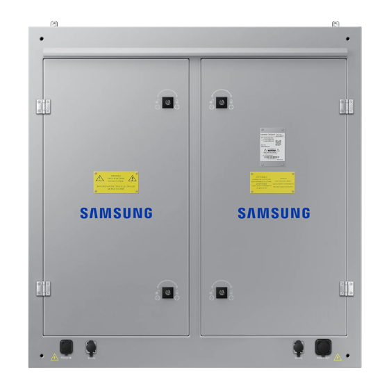
Page 16: Product Appearance
3.2 Product Appearance... - Page 17 XAT6.7&XAT10 XAT16...
-
Page 18: Product Design
3.3 Product design Decomposition chart... - Page 19 Assembly drawing...
-
Page 20: Product Main Components
3.4 Product main components Module Power Supply Receiving card DC output cables(9 pcs) Flat cables (9 pcs) -
Page 21: Led Display Screen Components
4. LED display screen components LED display screen connection Sending box(Model Name:LSFNS, Model Code: VG-LSFNS) Power LED and Switch: Power on or power off the sending box, the LED show the status of sending box. Power supply: AC power input, offer power for sending box. Power LED on back: Show the status of sending card. - Page 22 Function of sending box: 1. HDMI/DVI input; 2. HDMI/external audio input; 3. 12bit/10bit/8bit HD video source; 4. Resolution supported: 2048x1152, 1920x1200, 2560x960; 5. Resolution supported: 1440x900; 6. 1 light sensor interface; 7. Cascading supported; 8. 18bit gray scale processing and presentation; 9.
-
Page 23: Parts List And Parts Bom List
5. Parts List And Parts BOM List 5.1 Accessories list Sending box U Disk 3 core plug DVI cable BN81-15303A BN81-15312A BN81-15310A R2S8-22-1721 2S8-22-10025 R2J8-22-0125 R2L3-27-0104 USB cable AC power input cable Signal input cable AC power cascade cable BN81-15311A Different code by different project R2L3-27-0105 Different code by different project... -
Page 24: Spares List
5.2 Spares list Sending box Receiving card and HUB board Module Power supply BN81-15303A R2S8-22-1721 R2S8-22-1761(R3C6-88-10053) R4B3-10-10013 R2D8-25-10006 LED package Driver IC Mask Screws for Mask BN81-15332A BN81-15336A R3G1-27-0048 R2K2-22-0219 R2A8-24-10024 R2W8-22-1410 Tool for service (Front) AC power input cable Signal input cable AC power cascade cable Different code by different project R2W8-29-2868... -
Page 25: Parts Bom List
5.3 Parts BOM List Code Name Spec Unit Quantity R2S8-22-1721 Sending box MCTRL600-S(ROHS) R2W8-27-10392 Outdoor Cabinet 960*960*100mm 32X32 EMC Nova R4B3-10-10013 P10 module system(ROHS) R2J8-22-0125 3 core plug L 1.5M 2S8-22-10025 U Disk Control software/Setting files R2L3-27-0104 DVI cable L 1.5M R2L3-27-0105 USB cable L 1.5M... -
Page 26: Service Bom List
5.4 Service BOM List XAT 6.7 SVC BOM Item Spec Code.No SAMSUNG Spec Photo Quantity Unit A/S-LED MOUDLE:JDM,R4B3-06-10012,Module LED MOUDLE Module (P6.7 48*48 4S) R4B3-06-10012 (P6.7 48*48 4S) A/S-LED:JDM,R3G1-27-0048,LED LED (FM-Z2727RGBA-SH) R3G1-27-0048 2304 (FM-Z2727RGBA-SH) DRIVER IC IC (MBI5051B) R2K2-22-0219 A/S-DRIVER IC:JDM,R2K2-22-0219,IC (MBI5051B) - Page 27 ㎡ AC power cable(With A/S-AC CABLE:JDM,3D2-22-10359 ,2.5m AC CABLE 3D2-22-10359 connect) 110CM Seetronic-SAC3FPX ㎡ AC power cable(No A/S-AC CABLE:JDM, 3D2-22-10355 ,1.0m AC CABLE 3D2-22-10355 connect) 175CM,2.5-40 ㎡ AC power cable(No A/S-AC CABLE:JDM, 3D2-22-10356 ,1.0m AC CABLE 3D2-22-10356 connect) 30CM,2.5-40 ㎡ AC power cable(No A/S-AC CABLE:JDM,3D2-22-10357...
- Page 28 CONNECT Connect A/S-CONNECT PLATE:JDM, R2J8-42-0200 PLATE plate(130*100*4.0mm) R2J8-42-0200 ,Connect plate(130*100*4.0mm) CONNECT Connect A/S-CONNECT PLATE:JDM, R2J8-42-2403 PLATE plate(130*50*4.0mm) R2J8-42-2403 ,Connect plate(130*50*4.0mm) SERVICE A/S-SERVICE TOOL:JDM, R2W8-29-2868 ,Service Service tool (T type) R2W8-29-2868 TOOL tool (T type) A/S-SCREW:JDM,R2W8-22-1355,Screws (M3*8),Fix SCREW Screws (M3*8) R2W8-22-1355 SMPS, Air switch A/S-SCREW:JDM,R2W8-22-0050,Screws (M3*6),Fix SCREW...
- Page 29 XAT 10 SVC BOM Item Spec Code.No SAMSUNG Spec Photo Quantity Unit A/S-LED MOUDLE:JDM,R4B3-10-10013,Module LED MOUDLE Module (P10 32*32 2S) R4B3-10-10013 (P10 32*32 2S) A/S-LED:JDM,R3G1-27-0048,LED LED (FM-Z2727RGBA-SH) R3G1-27-0048 1024 (FM-Z2727RGBA-SH) DRIVER IC IC (MBI5051B) R2K2-22-0219 A/S-DRIVER IC:JDM,R2K2-22-0219,IC (MBI5051B) MASK Mask...
- Page 30 ㎡ AC power cable(No A/S-AC CABLE:JDM, 3D2-22-10356 ,1.0m AC CABLE 3D2-22-10356 connect) 30CM,2.5-40 ㎡ AC power cable(No A/S-AC CABLE:JDM,3D2-22-10357 ,1.0m AC CABLE 3D2-22-10357 connect) 30CM,2.5-40,2.5-40 SIGNAL A/S-SIGNAL CABLE:JDM,3D2-23-8025 ,100CM Signal cable 3D2-23-8025 CABLE Cat-5,two end network SIGNAL A/S-SIGNAL CABLE:JDM,3D2-23-8001 ,150CM Signal cable 3D2-23-8001 CABLE...
- Page 31 SERVICE A/S-SERVICE TOOL:JDM, R2W8-29-2868 ,Service Service tool (T type) R2W8-29-2868 TOOL tool (T type) A/S-SCREW:JDM,R2W8-22-1355,Screws (M3*8),Fix SCREW Screws (M3*8) R2W8-22-1355 SMPS, Air switch A/S-SCREW:JDM,R2W8-22-0050,Screws (M3*6),Fix SCREW Screws (M3*6) R2W8-22-0050 receiving card, hub board U DISK U DISK 2S8-22-10025 A/S-U DISK:JDM,2S8-22-10025,U DISK M10 BOWLS M10 Bowls R2W8-22-0466 A/S-M10 BOWLS:JDM,R2W8-22-0466...
- Page 32 XAT 16 SVC BOM Item Spec Code.No SAMSUNG Spec Photo Quantity Unit A/S-LED MOUDLE:JDM,R4B3-16-10004,Module LED MOUDLE Module (P16 20*20 1S) R4B3-16-10004 (P16 20*20 1S) LED R (DIP346-K2) R3G3-22-10002 A/S-LED:JDM,R3G3-22-10002,LED R (DIP346-K2) LED G (DIP346-K2) R3G3-23-10001 A/S-LED:JDM,R3G3-23-10001,LED G (DIP346-K2) LED B (DIP346-K2)
- Page 33 ㎡ AC power cable(With A/S-AC CABLE:JDM,3D2-22-10359 ,2.5m AC CABLE 3D2-22-10359 connect) 110CM Seetronic-SAC3FPX ㎡ AC power cable(No A/S-AC CABLE:JDM, 3D2-22-10355 ,1.0m AC CABLE 3D2-22-10355 connect) 175CM,2.5-40 ㎡ AC power cable(No A/S-AC CABLE:JDM, 3D2-22-10356 ,1.0m AC CABLE 3D2-22-10356 connect) 30CM,2.5-40 ㎡ AC power cable(No A/S-AC CABLE:JDM,3D2-22-10357...
- Page 34 SERVICE A/S-SERVICE TOOL:JDM, R2W8-29-2868 ,Service Service tool (T type) R2W8-29-2868 TOOL tool (T type) A/S-SCREW:JDM,R2W8-22-1355,Screws (M3*8),Fix SCREW Screws (M3*8) R2W8-22-1355 SMPS, Air switch A/S-SCREW:JDM,R2W8-22-0050,Screws (M3*6),Fix SCREW Screws (M3*6) R2W8-22-0050 receiving card, hub board U DISK U DISK 2S8-22-10025 A/S-U DISK:JDM,2S8-22-10025,U DISK M10 BOWLS M10 Bowls R2W8-22-0466 A/S-M10 BOWLS:JDM,R2W8-22-0466...
-
Page 35: Trouble Shooting List
6. Trouble shooting list 6.1 Display screen problem The whole display screen cannot light up Check if the display screen is power on. Check if the connection is broken between Sending box and the display screen, Check if the sending box is normal Check if the first cabinet is working normally in the display screen Check if the brightness setting is 0% Check if the software setting is correct. - Page 36 Part of the display screen cannot light up Check if the part is power on. Check if the power supply is broken Check if the connection is broken between cabinet and cabinet Check if the receiving card is normal Check if the software setting is correct Check if the program in receiving card is correct Part of the display screen is blinking Check if the connection is broken between cabinet and cabinet...
- Page 37 The display screen is out of control Check if the USB cable is connected well Check if the USB cable is broken Check if the software is running well The display screen display wrong image Check if the connection table setting is correct Check if the software setting is correct Check if the program in receiving card is correct...
-
Page 38: Cabinet Problem
6.2 Cabinet problem The cabinet cannot light up Check if the cabinet is power on Check if the connection is broken between cabinet to cabinet Check if the receiving card is normal Check if the power supply is broken in cabinet Check if the program for receiving card is correct The cabinet is blinking Check if the receiving card is broken... - Page 39 Part of the cabinet cannot light up Check if the power supply is broken Check if the flat cable is broken Check if the DC power cable is broken Check if the HUB board is broken Check if the module is broken Part of the cabinet is blinking Check if the flat cable is broken Check if the HUB board is broken...
-
Page 40: Module Problem
6.3 Module problem The module cannot light up Check if the DC cable is broken Check if the flat cable is broken Check if the module is broken Check if the last module is broken The module is blinking Check if the flat cable is broken Check if the module is broken Check if the last module is broken Block of module is broken or column of module is broken... - Page 41 Row of module is broken Check if the 4973 IC is broken Check if the soldering of the 4973IC is broken Pixel of module is broken Check if the led is broken Check if the soldering of led is broken...
- Page 42 How to check the status of the transmitting card? There are two lights on the transmitting card as shown as below. If everything is right, the Red one will be off and the Green one will be blinking. Otherwise the user needs to check graphics card setting, DVI cable and transmitting card. How to check the status of the receiving card? There are three lights on the receiving card as shown below If everything is right, the Red one is blinking, and the Green one is on (no blinking).
- Page 43 Checking Method Jump signal from the last module to another module Jump signal from the current row to the next row...
-
Page 44: Installation Guides
7. Installation Guides 7.1 Mechanical requirements and installation Support structure The support structure has to be provided and installed by the customer because they vary from project to project. The following issues must be considered: Weight tolerances: Ensure that the support structure and the floor on which or the wall against which the support structure has to be installed, is qualified to handle the complete weight of the LED display screen.(which can be provided by manufacturer. - Page 45 Installation of cabinets Fixing of connect plate...
- Page 46 Details of installation 1. First measure the under surface of the structure as a horizontal plane and the side of the structure as a vertical plane by spirit level as shown as below 2. First cabinet is placed in the middle of the bottom row with the stud rods in the middle of the corresponding slot as shown as below, do not fix the nuts tightly.
- Page 47 5. Measure the first row by spirit level, make sure it is installed horizontally, then fix the nuts tightly between the cabinets and the connect plates. 6. Place the middle cabinet in the second row, adjust it and fix it but not tight. Make sure it is installed horizontally and vertically, then fix it tightly as shown as below 7.
-
Page 48: Electrical Requirements
7.2 Electrical requirements Power system Power voltage must be in the range of the specification value. It is recommended to use a power distribution system (a power distribution system with a separate neutral and grounding conductor in order to avoid large ground current loops due to voltage differences in the neutral conductor. - Page 49 Lighting Strike Protection of Electric Closet Every electric closet of LED display screen must be installed with lightning protection device equipment. The requirement specification should be same as shown below. Nominal discharge current In (8/20µs) :20 kA The maximum discharge current Imax (8/20µs):40 kA Voltage protection level: Up in ln AC385-505V:≤1.7kV TA ˂25ns...
- Page 50 Cooling System If the customer want that the LED screen working normally for a long time. He should pay attention for the cooling system for control the temperature inside the steel structuer, at least less than 45 degrees Celsius. A. If the LED display dimension is less than 20 square meter, not need to install air condition, 2 air flow is enough.
-
Page 51: Connection Of The Led Screen
8. Connection of the LED screen 8.1 Connection for equipments Connection between Sending box and PC 8.2 Port of Cabinet AC Power input AC Power input Signal socket... -
Page 52: Connection For Power Cables
8.3 Connection for power cables Usually the length of the AC input cable depend on the distance between the power distribution and LED display screen, it is not certain. The AC cascade cable: 3*2.5 ㎡ 50cm,two end with connector. Attention: For 220-240V AC power voltage countries and areas, each AC input cable can offer power for 5 cabinets. -
Page 53: Connection For Data Cables
8.4 Connection for data cables Usually the length of the AC input cable is 50M, but sometimes it depend on the distance between the control room and LED display screen, it is not certain. The signal cascade cable: Cat-5 or Cat-6 60cm, two end with connector. The signal cascade cable: Cat-5 or Cat-6 120cm, two end with connector. -
Page 54: Cabinet Arrangement Drawings Sample
8.5 Cabinet arrangement drawings sample Every project there will be a cabinet arrangement drawing to show how to install the cabinet in turn. This is only a sample to show you what it like. Note: For waterproof, please use the water-proof cover to cover the last cabinet which have no connector to the next cabinet. -
Page 55: Control System Setting
9. Control system setting 9.1 Software setup It is sample to install the <NovaLCT> as below: Double-click NovaLCT setup file,(see Fig.9-1), select <Next> to start, follow the guides to finish the setup, software version:NovaLCT V5.2.0 . Fig 9-1 When the setup of the < NovaLCT> is completed, the <LED software> will show up in the <Start/<Program>. -
Page 56: Novalct Main Interface
9.2 NovaLCT Main interface This section describes how to use NovaLCT to set screen parameters as follows: Enter NovaLCT main interface Step 1:Start “NovaLCT", click ""User" → "Advanced Login", enter `User login` window as shown in Fig.9-3 Fig 9-3 Step 2:Input the password `admin`, enter the NovaLCT main interface for advanced users as shown in Fig 9-4 Fig 9-4... -
Page 57: Main Menu
9.3 Main Menu Menu Description This is used to reconnecting the NovaLCT to System Reconnect the synchronous system. Screen Configuration Shortcut button: (Advanced This is used for configuration of the LED user) screens. Shortcut button: This is used for adjusting the LED display Brightness brightness. - Page 58 Menu Description View correction coefficients of the receiving card and module. Module Flash Save correction coefficients in the receiving card and module. Test whether Flash is normal. Receiving Card Relay Set parameters for the receiving card relay. (Advanced Reset the time of the receiving card. user) Configure Information...
- Page 59 Menu Description management of video processor. Module ID Perform module ID configuration to make Setting module management easier. Some modules do not support ID configuration, please (Advanced contact NovaStar’s technicians for details. user) Includes Reset Run Time, Brighter Pixel Correction and Bite Error Detection. l Reset Run Time: Reset the run time displayed on the LCD of each cabinet.
-
Page 60: Screen Config
9.4 Screen Config To configure a LED display with system configuration files, click Screen Config button fromthe tool bar or select Tools->Screen Config from the main menu of the NovaLCT application main interface to open the Screen Config window. Shown in Fig.9-5 is the Screen Config window. - Page 61 Sending box setting Enter `Screen Config`, choose `Sending Board` as shown in Fig 9-6. Fig 9-6 In this interface, the user can set up `Sending Board`, `Scan Board` and `Screen Connection ` Attention: Usually the resolution of transmitting card is bigger than the resolution of the LED display screen.
- Page 62 Scan Board setting Choose the `Scan Board` as shown in Fig 9-7. Fig 9-7 Quantity This is the number of LED displays that are to be configured. Configure This button is used to load the Screen Number to the NovaLCT application. Read form HW This is used for the application to read the LED display information from the hardware.
- Page 63 This is used to save screen information files as screen information file (*.scr). Send to HW This is used to send the LED display configuration settings to the connected sending card. Restore Factory Settings Reset current parameter configuration to factory settings. Restore System Configuration Reset current operating status of the system (or sending card, or receiving card) to the status in the backup file.
- Page 64 Screen connection setting Choose the `Screen Connection` as shown in Fig 9-8. Fig 9-8 Quantity This is the number of LED displays that are to be configured. Configure This button is used to load the Screen Number to the NovaLCT application. Read form HW This is used for the application to read the LED display information from the hardware.
- Page 65 Reset current parameter configuration to factory settings. Restore System Configuration Reset current operating status of the system (or sending card, or receiving card) to the status in the backup file. Back Up System Configuration Back up current configuration parameters. Save System Configuration File Save system configuration parameters as a file.
-
Page 66: Advanced Color Configuration
9.5 Advanced color configuration Advanced color configuration includes factory setting, configure color space, color temperature table and color adjustment. The target color space plan and color temperature table configured here can be called directed when adjusting brightness. Choose Settings > Advanced Color Configuration, as shown in Figure 9-9. Figure 9-9 Advanced color configuration Factory Setting Current Gain: Some chips support current gain control. - Page 67 Draw black lines and common color temperature points: When this option is selected, a black line (color temperature curve) and common color temperature points (solid dots) are shown. Original color space: It is suggested to use a light gun to measure current CIE coordinates and brightness and fill out properly, use original color space as basis for adjusting color temperature.
- Page 68 : Add color temperature segments. : Compile selected color temperature segment. : Delete selected color temperature segment. : Clear all color temperature segment. : Save the color temperature table to local space. Color Adjustment Adjust hue, contrast and saturation of the LED display. This function is only supported NovaStar Pro HD for the moment.
-
Page 69: Adjust The Brightness And Gamma
9.6 Adjust the brightness and Gamma Click Brightness button from the tool bar or select Setting->Brightness from the main menu of the NovaLCT application main interface to open the Display Adjustment window for brightness, Gamma and color temperature adjustment. There are two methods to adjust the brightness: manual adjustment and automatic adjustment, after adjustment is done, click and save the adjustment results to hardware. - Page 70 Select independent Gamma adjustment mode, including Red Gamma, Green Gamma and Blue Gamma. (Only the MCTRL4K and MCTRL660 PRO support individual Gamma adjustment for RGB.) Set the grayscale bit value. Drag the slider to adjust the Gamma value. Under Recommended Gamma, select the Gamma mode, including Original, Mode A and Mode B.
- Page 71 Advanced Adjustment You can configure multiple time points, each point can be configured with specified brightness or environment brightness. Specified brightness: The brightness of LED display from certain time on designated by the user, the brightness is fixed. Environment brightness: The brightness of environment from certain time on designated by the user, the software will automatically adjust the LED display brightness in accordance with the parameters set by the users as well as environment brightness information collected by light sensors so that the LED display can exhibit proper...
- Page 72 When light sensor fails, adjust the brightness to: Enabled after being checked. If not enabled, when light sensor fails, the brightness will remain at the latest updated brightness value. : Divide the portion between the maximum environment brightness and minimum environment brightness into designated equal parts, the portion between the maximum and minimum LED display brightness is also divided into similar equal parts.
- Page 73 Step 1 Click , check Adjust by Light Sensor, then click Step 2 If you have not finished configuration of light sensor, it is need to configure the light sensor then, the detailed operation, please refer to the step 3) in Advanced Adjustment.
-
Page 74: Screen Control
9.7 Screen Control Start NovaLCT and click to enter the Screen Control window. The Screen Control window Black Out Show nothing on the LED display. Freeze Always show the current image frame of the LED display. Normal Switch the LED display back to normal from Black Out or Freeze. Self Test Show the test images generated by the receiving card for LED displays aging test or error detecting. -
Page 75: Check Hardware Information
9.8 Check Hardware Information Select Settings > Hardware Information to enter the Hardware Information page. The Hardware Information page Current Time of Hardware This is the date and time of the current synchronous system. Click Read button to update the hardware time shown in the Time panel. Click Set button to set the time of the current synchronous system as that of the computer. -
Page 76: Brightness/Color Calibration
9.9 Brightness/Color Calibration Online Calibration Online calibration is that NovaCLB (calibration software) connect NovaLCT through network for calibration of LED displays. It supports single-screen mode and combined-screen mode. Current Serial Port This is the serial port through which the LED display to be calibrated is connected to the computer. - Page 77 Coefficients Management This page is to adjust the calibration coefficients for better calibration performance. The Manage Coefficients page is shown below The Manage Coefficients page Upload Coefficients Upload a calibration coefficients database to the LED display. Save coefficients to database This operation is to read back the calibration coefficients form the LED display and save them to a database file.
- Page 78 bright lines. The page for upload coefficients step 1 Browse Click this button to select the calibration coefficients database file to be uploaded. Type The type of the selected calibration coefficients database is shown here. There are two database types, screen database and cabinet database. A screen database contains calibration coefficients for a whole display while a cabinet database contains calibration coefficients for one or multiple cabinets.
- Page 79 Screen The page for uploading calibration coefficients in Screen way Pixel The page for uploading calibration coefficients in Pixel way...
- Page 80 Topology or List The page for uploading calibration coefficients in Topology or List way Screen If this option is selected, calibration coefficients for the whole display will be uploaded. Pixel Select this option to upload calibration coefficients to the specified pixel area. Topology or List Selected this option to upload calibration coefficients to the cabinets selected in the cabinet array sketch map or the cabinet list.
- Page 81 Fast Upload The uploading speed will be set as maximum thus the time required for uploading is minimized if this option is selected. Stable Upload The uploading process is more stable and reliable for this option. But the time required is longer than the Fast Upload option.
- Page 82 The page for saving calibration coefficients to a new database Screen-Database Select this option if it is to save the calibration coefficients to a new screen database. Cabinet-Database Select this option if it is to save the calibration coefficients to a new cabinet database. Create Click this button to create a new screen database or a cabinet database according to the settings.
- Page 83 The page for specifying the display area for coefficients saving Screen Check this option if the calibration coefficients for the whole display are to be saved. If the database for saving the coefficients is a cabinet database, this option will be unavailable. Pixel Check this option to select the pixel area for which the calibration are to be saved.
- Page 84 Set coefficients for a new receiving card Step 1 Specify the LED display area that the new receiving card works for. Shown as below which is the page for specifying the area. The page for specifying the working area of the new receiving card Step 2 Select the calibration coefficient source.
- Page 85 Browse Click this button to select the database that the calibration coefficients for the new receiving card are from. If the selected is a cabinet database, the cabinet ID should also be specified from the Cabinet ID drop list. Cabinet ID If the selected database is a cabinet database, the IDs of the cabinets of which the calibration coefficients are contained in the database will be list in the drop list.
- Page 86 Use the slide bar to adjust the red brightness of the calibration coefficients. Green Use the slide bar to adjust the green brightness of the calibration coefficients. Blue Use the slide bar to adjust the blue brightness of the calibration coefficients. Advanced Click this item to switch to the advanced adjustment page.
- Page 87 Simple The color bar under each side bar indicates the color to be shown when adjusting. Note: l If the cabinet driven by the new receiving card is only different from the surrounding cabinets in brightness, simple adjustment is sufficient. l If the cabinet driven by the new receiving card is different from the surrounding cabinets in color, adjust the brightness, saturation and hue through the advanced adjustment page for better image quality.
- Page 88 Set coefficients for a new module Step 1 Specify the cabinet which the new module is in. The page for specifying the cabinet which the new module is in Step 2 Double click the selected cabinet, and select the new module. The page for specifying the new module Module Size Set the pixel array size of a module here.
- Page 89 according to those of the surrounding modules are used for the new module because the coefficients saved in the receiving card or the database are not suitable for the new module. The page for selecting the calibration coefficients source Note: l One or more surrounding modules can be selected for generating the calibration coefficients for the new module.
- Page 90 Adjust Coefficients If some parts of the LED display are different from the rest in color, the color of these areas can be adjusted by modifying the corresponding calibration coefficients. Step 1 Select the areas to be adjusted. The page for selecting the area to be adjusted Step 2 Select the adjustment type.
- Page 91 The page for Effect As Other Selected Area Note: l If Adjust Own Effect option is selected, NovaLCT will acquire the calibration coefficients of the selected area for the hardware. Adjustment on these coefficients is independent to the other area of the LED display. l If Effect As Other Selected Area is selected, NovaLCT will adjust the calibration coefficients of the selected area according to those of the reference areas and make the selected area looks similar to the...
- Page 92 Apply The Effect To Other Area The adjustment operations in Step 2 and Step 3 can also be applied to other areas that need the same adjustment. The page for Apply The Effect To Other area Apply Apply adjustment operations to the selected area. Note: l If the adjustment operations are to be applied to another area, the problem of this area should be similar to the area selected in Step 1.
- Page 93 Erase or Reload Coefficients Erase coefficients: erasing calibration coefficients of the whole display or any cabinets. Reload coefficients: reload the calibration coefficients lastly saved in hardware. The page for erasing calibration coefficients Screen Select this option to erase all calibration coefficients for the whole display. Topology or List Select this option to select the cabinets from the cabinet array sketch or the cabinet list of which the calibration coefficients are to be erased.
- Page 94 Resetting Calibration Coefficients Set the calibration coefficients again for the screen or a specified area according to the module size or pixels. After all the coefficients are reset, click Save to HW so that the coefficients can take effect. Resetting calibration coefficients...
-
Page 95: Hardware Monitoring
9.10 Hardware Monitoring NovaLCT supports monitoring status of sending cards, receiving cards and monitoring cards, as well as temperature, humidity, smoke, fan, power supply, ribbon cable, cabinet door and smart module. NovaLCT is applicable to both ordinary screen and combined screen. - Page 96 Refresh Period Modify refresh period and reread times when reading the status failed at the refresh period interface, wherein the period is the period of refreshing the monitoring data. If all screens are registered to the NovaCare server, check “Automatic Refresh” to perform remote monitoring.
- Page 97 Hardware Configuration The hardware configuration interface provides all hardware monitoring related setting options. The monitoring functions can only be realized by using the monitoring card, so Connect to Monitoring Card option should be selected before the refresh-related options are set. Hardware configuration : Click to enter the advanced setting of monitor, as shown in the figure below.
- Page 98 Each receiving card is connected with one monitoring card by default. Click to pop up with the interface below. Please set the number of receiving cards (0 or 1) according to the actual situation. Click to restore the default values immediately. Connect to Monitoring Card If this option is selected, the monitoring data of the monitoring card will be displayed.
- Page 99 Alarm Configuration Display alarm or fault information when setting the temperature, humidity, fan speed and voltage critical value. Data alarm configuration Control Configuration Set the rules for auto temperature and smog control. Control configuration Click to add control information.
- Page 100 Email Setting Operation procedures Select the Enable Email Notification option to show the related configuration items as shown below Email setting − : Add the receiver. − : Edit the receiver. − : Delete the receiver. If email notification is desired, information related to the email sender, receiver and email is required to be set.
- Page 101 Email Log If the Enable Email Notification option is selected, you can click Email Log to view the email notification log history as shown in the following figure. You can search the logs by time and delete the undesired ones. The History window for notification emails checking The details of operation for NovaLCT, please refer to the read as shown below: Note: Until now, the monitoring card only support...
-
Page 102: Servicing
10. Servicing 10.1 Cleaning For outdoor LED display screen Due to outdoor use the LED display screen are exposed to all kinds of weather conditions. Sand, dust, smog and other dirty things on the LED display and because of that the performance of the LED display may be effected, So regular cleaning on LED display is recommended. -
Page 103: Calibration
10.2 Calibration Factory calibration In order to achieve color uniformity among all cabinets of the same display the cabinets can be color calibrated to improve display effect of the LED display screen. The manufacturer can do calibration before goods are delivered out of factory. Site calibration When the LED display screen is running for a long time, for example for one year, some part of the display screen may play a different image from other parts. -
Page 104: Replacement Steps
10.3 Replacement steps Front Service: Module Power off the cabinet where the module is in Remove the module from front by front service tool as shown below Remove the DC power cable and flat cable from the bad module, and then take off the bad module from cabinet by hand as shown below Bring a new module, connect the DC power cable and flat cable into the new module Put the new module on the cabinet and then install it into cabinet by front service tool as... - Page 105 Power supply Power off the cabinet where the power supply is in Remove the modules from front by front service tool as the modules service steps as shown “Module replacement” Take off all the cables connected to the power supply as shown below Remove the patching board by screwdriver and then remove the bad power supply from the cabinet as shown below Install the spare power supply into the cabinet and then install the patching board by...
- Page 106 HUB board Power off the cabinet where the HUB board is in. Remove the modules from front by front service tool as the modules service steps as shown “Module replacement” Remove the bad HUB board from the cabinet as shown below Take off all the cables from bad HUB board and remove receiving card from HUB board as shown below Bring a new HUB board and install back the receiving card, then connect back the cables...
- Page 107 Receiving card Power off the cabinet where the receiving card is in. Remove the modules from front by front service tool as the modules service steps as shown “Module replacement” Remove the HUB board from front by screwdriver as HUB board service steps as shown “HUB board replacement”...
- Page 108 Air switch Power off the cabinet where the bad air switch is in, Remove the modules from front by front service tool as the modules service steps as shown “Module replacement” Remove the cover for the air switch , take off all the cables on the bad air switch, and then remove the it from the cabinet as shown below Bring a new air switch and install it into the cabinet, install all the cables into the new air switch, and then install the cover back on the cabinet as shown below...
- Page 109 Power cascade cable and Signal cascade cable Power off the cabinet where the bad cables are in. Remove the modules from front by front service tool as the modules service steps as shown “Module replacement” Open the door oft he cabinet by screwdriver from front as shown below. Service the bad cables as shown below After cables service , close the door of the cabinet as shown below Install back the modules from front by front service tool as the modules service steps as...
- Page 110 Back Service: Open cabinet Before replace the bad parts in cabinet, you need to open the back door of cabinet by key as shown below...
- Page 111 Before you replace the electrical parts, please ware the ESD protection gloves first. Module Power off the cabinet where the module is in Remove the module from back by hand as shown below Remove the DC power cable and flat cable from the bad module, and then take off the bad module from cabinet by hand as shown below Put the new module on the cabinet and then install it into cabinet as shown below Connect the DC power cable and flat cable into the new module as shown below...
- Page 112 Notice: After change modules, must check if the lock is fine as shown below: Power supply Power off the cabinet where the power supply is in Take off all the cables connected to the power supply as shown below Remove the patching board by screwdriver and then remove the bad power supply from the cabinet as shown below Install the spare power supply into the cabinet and then install the patching board by screwdriver as shown below...
- Page 113 HUB board Power off the cabinet where the HUB board is in, Take off all the cables from bad HUB board as shown below Remove the bad HUB board from the cabinet and then remove the receiving card from the bad HUB board as shown below Bring a new HUB board and install the receiving card into the new HUB board, and then install the new HUB board on cabinet as shown below...
- Page 114 Receiving card Power off the cabinet where the receiving card is in, Take off the bad receiving card from the HUB board as shown below Bring a new receiving card and install it into the HUB board as shown below Power on the cabinet Air switch Power off the cabinet where the bad air switch is in,...
- Page 115 AC input cable with connector Power off the cabinet where the bad AC input cable is in Remove the bad one from the cabinet Install the new one. Power on the cabinet Signal input cable Power off the cabinet where the bad Signal input cable is in Remove the bad one from the cabinet Install the new one Power on the cabinet...
- Page 116 Flat cable Remove the bad one Install the new one. DC power cable Power off the cabinet where the DC cable is, Take off the bad one Install the new one. Turn on the cabinet.
-
Page 117: Appendix
Product damage caused by customer`s mishandling or wrong repair. If a product damage is caused by: External impact or drop. Use of supplier or separately sold product unspecified by Samsung. Repair from a person besides an engineer of outsourcing service company or partner of Samsung Electronics Co.Ltd. -
Page 118: Recycle Mark
11.2 Recycle Mark This marking on the product, accessories or literature indicates that the product and its electronic accessories(e.g. power supply, cable, USB...) should not be disposed of with other household waste at the end of their working life. To prevent possible harm to the environment or human health from uncontrolled waste dispasal, please separate these items from other types of waste and recycle them responsibly to promote the sustainable reuse of material resources.