Advertisement
Table of Contents
- 1 Important Safety Information
- 2 Transportation and Storage
- 3 Product Overview
- 4 Positioning & Installation
- 5 Installation Errors
- 6 Control Panel
- 7 Remote Control
- 8 Operation Modes
- 9 Water Drainage
- 10 Maintenance
- 11 Further Safety Information
- 12 Troubleshooting
- 13 Technical Specification
- Download this manual
Advertisement
Table of Contents

Related Manuals for Pro-Elec PEL01201


Summary of Contents for Pro-Elec PEL01201
- Page 1 LOCAL AIR CONDITIONER Model: PEL01201...
-
Page 2: Important Safety Information
Please read these instructions carefully before use and retain for future reference. IMPORTANT SAFETY INFORMATION • Do not use any means to accelerate the defrosting process or to clean, other than those recommended by the manufacturer. • The appliance shall be stored in a room without continuously operating ignition sources (for example: open flames, an operating gas appliance or an operating electric heater). -
Page 3: Transportation And Storage
• Do not install and use the appliance in a bathroom or other humid environments. • Do not pull out the mains plug to turn off the appliance. • Do not place cups or other objects on the appliance to prevent water or other liquids from spilling into the air conditioning. -
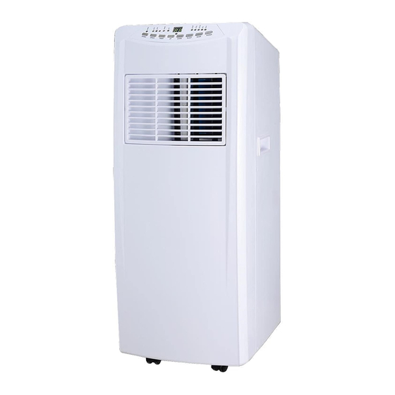
Page 4: Product Overview
PRODUCT OVERVIEW Front 1 Control panel 2 Air-outlet 3 Power button 4 Handle 5 Castor Back Filter frame upper Exhaust connector Filter frame lower Rubber plug 10 Plug cap 11 Power cord Accessories 12 Exhaust hose 13 Adjustable window guide 14 Exhaust hose adapter 15 Remote control 16 Filter... -
Page 5: Positioning & Installation
POSITIONING & INSTALLATION Positioning Warning: before using the local air conditioning, keep it upright for at least two hours. • The air conditioner must stand upright on an even surface. • Do not position near a bath, sink or other permanently damp or wet areas. •... -
Page 6: Installation Errors
INSTALLATION ERRORS To operate efficiently the air must be able to flow freely into the exhaust hose. To assist this: • Avoid any sharp bends or kinks in the exhaust hose. • Keep it as level as possible. • Keep its length as short as possible. The maximum extension length of the exhaust pipe is 1.5m. -
Page 7: Remote Control
REMOTE CONTROL 1. POWER 2. TIMER 3. DOWN 4. MODE 5. UP 6. FAN 7. SLEEP OPERATION MODES Cooling Mode • After the air conditioner turns on, the default setting is cooling mode with a temperature of 22°C and low fan speed. •... -
Page 8: Water Drainage
Compressor Protection After powering on, or a restart, there is a three minute delay before the compressor starts to operate. This helps to prolong the life of the compressor. WATER DRAINAGE • The air conditioner has an internal water tank to collect water that accumulates during the cooling process. -
Page 9: Further Safety Information
Seasonal Cleaning If the air conditioner is not going to be used for a long time, please follow the steps below: • Unplug the air conditioner from the mains. • Remove the drainage plug and empty the internal water tank. •... - Page 10 Presence of fire extinguisher • If any hot work is to be conducted on the refrigeration equipment or any associated parts, appropriate fire extinguishing equipment shall be available to hand. Have a dry powder or CO2 fire extinguisher adjacent to the charging area. No ignition sources •...
- Page 11 Initial safety checks shall include: That capacitors are discharged: this shall be done in a safe manner to avoid possibility of sparking. That there no live electrical components and wiring are exposed while charging, recovering or purging the system. That there is continuity of earth bonding. Repairs to sealed components •...
- Page 12 (Detection equipment shall be calibrated in a refrigerant-free area). • Ensure that the detector is not a potential source of ignition and is suitable for the refrigerant used. Leak detection equipment shall be set at a percentage of the LFL of the refrigerant and shall be calibrated to the refrigerant employed and the appropriate percentage of gas (25%maximum) is confirmed.
- Page 13 Prior to recharging the system it shall be pressure tested with OFN. The system shall be leak tested on completion of charging but prior to commissioning. A follow up leak test shall be carried out prior to leaving the site. Decommissioning •...
- Page 14 • Empty recovery cylinders are evacuated and, if possible, cooled before recovery occurs. • The recovery equipment shall be in good working order with a set of instructions concerning the equipment that is at hand and shall be suitable for the recovery of flammable refrigerants.
-
Page 15: Troubleshooting
TROUBLESHOOTING Trouble Cause Solution • Power is off • Switch the power on • Water-full indicator is on • Drain internal water tank • The ambient temperature is too • Recommend to use the low or too high machine in at the temperature range of 7-35 C (44-95 •... -
Page 16: Technical Specification
TECHNICAL SPECIFICATION Main voltage 220-240V ~ 50Hz Rated input power 1350W Power standby mode 1.0W Cooling capacity 3.52kW (12,000BTU/h) Dehumidifying capacity 28L/24hr Air flow 380m³/h Sound power level 65dB (A) Refrigerant/charge R290/195g Global warming potential 0.585kgCO Energy efficiency ratio (EER) Energy efficiency class Fan speeds Thermostat...
Need help?
Do you have a question about the PEL01201 and is the answer not in the manual?
Questions and answers