
Related Manuals for HYDAC ELECTRONIC Aqua Sensor AS 1200


Summary of Contents for HYDAC ELECTRONIC Aqua Sensor AS 1200
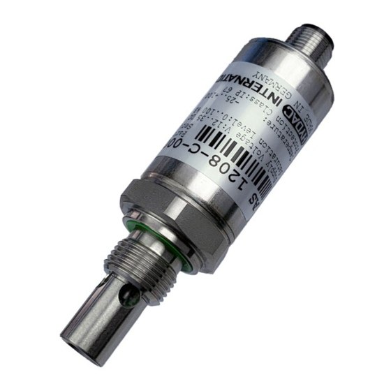
- Page 1 Aqua Sensor AS 1200 Benutzerhandbuch (Originalanleitung) User manual (Translation of original instructions)
-
Page 2: Table Of Contents
Aqua Sensor AS 1200 Inhalt 1 Allgemeines ......................... 4 2 Sicherheitshinweise ....................4 3 Montage ........................4 4 Funktionsweise ......................5 4.1 Idealer Sättigungsgrad in Hydraulik und Schmiersystemen ......5 4.2 Arbeitsbereich AS 1200 ..................6 5 Funktionen ........................6 ... - Page 3 Aqua Sensor AS 1200 Vorwort Für Sie, den Benutzer unseres Produktes, haben wir in dieser Dokumentation die wichtigsten Hinweise zum Bedienen und Warten zusammengestellt. Sie dient Ihnen dazu, das Produkt kennen zu lernen und seine bestimmungsgemäßen Einsatzmöglichkeiten optimal zu nutzen.
-
Page 4: 1 Allgemeines
Fremdeingriffe in das Gerät führen zum Erlöschen jeglicher Gewährleistungsansprüche. 2 Sicherheitshinweise Der Aqua Sensor AS 1200 ist bei bestimmungsgemäßer Verwendung grundsätzlich betriebssicher. Um jedoch Gefahren für Benutzer und Sachschäden infolge falscher Handhabung des Gerätes zu vermeiden, beachten Sie bitte die folgenden Sicherheitshinweise: ... -
Page 5: 4 Funktionsweise
Aqua Sensor AS 1200 4 Funktionsweise Die Aqua-Sensoren der Serie AS 1200 sind Wasser- und Temperatursensoren zur kontinuierlichen und präzisen Online-Überwachung von Wasser in Hydraulik- und Schmierfluiden sowie Diesel. Sie erfassen den Wassergehalt relativ zur Sättigungskonzentration (Sättigungspunkt). Hierbei bedeuten 0% wasserfreies Öl und 100% vollkommen mit Wasser gesättigtes Öl. -
Page 6: Arbeitsbereich As 1200
Aqua Sensor AS 1200 4.2 Arbeitsbereich AS 1200 Um bleibende Schäden am Sensorelement des AquaSensors AS 1200 zu vermeiden, ist darauf zu achten den Sensor nicht außerhalb des zulässigen Arbeitsbereiches (Medientemperaturbereich von -25 bis +125°C ) zu betreiben. 5 Funktionen Ausführung mit Analogausgängen... -
Page 7: Schaltausgänge
Aqua Sensor AS 1200 5.3.2 Schaltausgänge Verhalten innerhalb des vorgegebenen Temperaturbereichs Die Schaltausgänge sind nur im Arbeitsbereich aktiv, wenn: aktuelle Temperatur ≥ Aktivierungstemperatur und aktuelle Temperatur < Übertemperatur Die Schaltpunkte beziehen sich auf die Sättigung. Zu jedem Schaltausgang kann ein Schaltpunkt und ein Rückschaltpunkt (RP) eingestellt werden. - Page 8 Aqua Sensor AS 1200 Einstellbereiche der Parameter Messbereich Untere Grenze Obere Grenze Mindestabstand Schrittweite* Sättigungsgrad von RP von SP zw. RP und SP in % in % in % in % 0 .. 100 100,0 * Die in der Tabelle angegebenen Bereiche sind im Raster der Schrittweite einstellbar.
-
Page 9: Grafische Darstellung Des Ausgangsverhaltens
Aqua Sensor AS 1200 5.3.4 Grafische Darstellung des Ausgangsverhaltens Stand: 23.02.2021 HYDAC ELECTRONIC GMBH Mat. Nr.: 670050... -
Page 10: 6 Elektrischer Anschluss
Aqua Sensor AS 1200 6 Elektrischer Anschluss Signal Sättigungsgrad AS 1200 -C Signal Temperatur SP2, Warnung AS 1200 -2 SP 1, Alarm * HSI = HYDAC Sensor Interface (HYDAC-interne Kommunikations-Schnittstelle) = (U – 10 V) / 20 mA [k] Stand: 23.02.2021 HYDAC ELECTRONIC GMBH Mat. -
Page 11: 7 Technische Daten
Aqua Sensor AS 1200 7 Technische Daten Eingangskenngrößen AS 1200-C AS 1200-2 Messbereich (Sättigungsgrad) 0 .. 100 % Messbereich (Temperatur) -25 .. +100 °C Betriebsdruck - 0,5 .. 50 bar 630 bar Druckfestigkeit Mechanischer Anschluss G3/8A ISO 1179-2 Anzugsdrehmoment, empfohlen 25 Nm Medienberührende Teile... -
Page 12: 8 Bestellangaben
Aqua Sensor AS 1200 8 Bestellangaben 1 2 0 8 - X - 000 Medium 2 = Mineralölbasisende Fluide, Diesel oder Phosphatester basierende Fluide 2) 3) Anschlussart mechanisch 0 = G 3/8A ISO 1179-2 Anschlussart elektrisch 8 = Gerätestecker M12x1, 5-pol. (ohne Kupplungsdose) -
Page 13: 9 Geräteabmessungen
Aqua Sensor AS 1200 9 Geräteabmessungen Elastomer Profildichtring Stand: 23.02.2021 HYDAC ELECTRONIC GMBH Mat. Nr.: 670050... -
Page 14: Elektrisch
Aqua Sensor AS 1200 10 Zubehör 10.1 Elektrisch ZBE 08 (5-pol.) Kupplungsdose M12x1, abgewinkelt Bestell-Nr.: 6006786 ZBE 08-02 (5-pol.) mit 2m Leitung Bestell-Nr.: 6006792 ZBE 08-05 (5-pol.) mit 5m Leitung Bestell-Nr.: 6006791 ZBE 08S-02 (5-pol.) mit 2m Leitung geschirmt Bestell-Nr.: 6019455 ZBE 08S-05 (5-pol.) -
Page 15: Hda 5500
Aqua Sensor AS 1200 11 Anzeigen 11.1 HDA 5500 Das HDA 5500 in der Ausführung HDA 5500-1-1-AC-000 bzw. HDA 5500-1-1-DC-000 ist ein Anzeigegerät mit 4 programmierbaren Schaltausgängen, speziell auf den AS 1200 zugeschnitten. In Verbindung mit dem HDA 5500 ist es möglich, die aktuellen Messwerte zur Anzeige zu bringen. -
Page 16: Hmg 2500 Und Hmg 4000
Aqua Sensor AS 1200 11.3 HMG 2500 und HMG 4000 Mobile Handmessgeräte mit einem vollgrafikfähigen Farbdisplay zur Messwertanzeige bzw. Messwertaufzeichnung des AS 1200. In Verbindung mit einem der o.g. HMGs können die aktuellen Messwerte auf dem Display angezeigt werden. Die Aufnahmen können auf den HMGs auch gespeichert und bearbeitet werden (genaue Beschreibung siehe jeweilige Bedienungsanleitung). - Page 17 Aqua Sensor AS 1200 HYDAC ELECTRONIC GMBH Hauptstr. 27 D-66128 Saarbrücken Germany Web: www.hydac.com E-Mail: electronic@hydac.com Tel.: +49 (0)6897 509-01 Fax.: +49 (0)6897 509-1726 HYDAC Service Für Fragen zu Reparaturen steht Ihnen der HYDAC Service zur Verfügung. HYDAC SERVICE GMBH Hauptstr.
- Page 18 Notizen / Notes / Notes ...
- Page 19 Aqua Sensor AS 1200 User manual (Translation of original instructions)
- Page 20 Aqua Sensor AS 1200 Contents General ......................... 4 Safety Information ....................... 4 Installation ........................4 Function principle ....................... 5 Ideal saturation level in hydraulic and lubrication systems ......5 Working range AS 1200 ..................6 Functions ........................6 Model with analogue outputs ................6 Error Messages ....................
- Page 21 Aqua Sensor AS 1200 Preface This manual provides you, as user of our product, with key information on the operation and maintenance of the equipment. It will help you to familiarise yourself with the product and assist you in obtaining maximum benefit in the applications for which it is designed.
-
Page 22: General
HYDAC personnel will invalidate all warranty claims. 2 Safety Information The Aqua Sensor AS 1200 presents no safety concerns when operated in accordance with this user manual. However, in order to avoid any risk to the operator or any damage due to incorrect handling of the unit, please adhere strictly to the following safety instructions: ... -
Page 23: Function Principle
Aqua Sensor AS 1200 4 Function principle AS 1200 Aqua Sensors are water and temperature sensors designed for the continuous and precise online monitoring of hydraulic and lubrication fluids as well as diesel. They measure the water content in relation to the saturation level(saturation level). The value 0 % corresponds to oil which is free of water and 100 % is an indication for oil which is completely saturated with water. -
Page 24: Working Range As 1200
Aqua Sensor AS 1200 4.2 Working range AS 1200 In order to avoid lasting damage to occur to the sensor element of the AS 1200, make sure the sensor is not operated outside the permitted working range (fluid temperature range from -25 to +125°C) -
Page 25: Switching Outputs
Aqua Sensor AS 1200 5.3.2 Switching outputs Behaviour within the prescribed temperature range The switching outputs are only active in the working range if: actual temperature ≥ activation temperature and actual temperature < over-temperature The switching points relate to the saturation. A switching point and a switch-back point (reverse switching point RP) can be set for each switch output. - Page 26 Aqua Sensor AS 1200 Setting ranges of the parameters Measurement range Lower limit of Upper limit of Minimum Increment* Saturation Level difference betw. RP and SP in % in % in % in % 0 .. 100 100.0 * All ranges listed in the table can be adjusted by the increments shown.
-
Page 27: Graphic Representation Of The Output Behaviour
Aqua Sensor AS 1200 5.3.4 Graphic representation of the output behaviour Edition: 2021-02-23 HYDAC ELECTRONIC GMBH Part no.: 670050... -
Page 28: Electrical Connection
Aqua Sensor AS 1200 6 Electrical connection Signal saturation level AS 1200 -C Signal temperature SP2, Warning AS 1200 -2 SP 1, Alarm * HSI = HYDAC Sensor Interface (HYDAC's own communication interface) = (U – 10 V) / 20 mA [kW]... -
Page 29: Technical Details
Aqua Sensor AS 1200 7 Technical details Input data AS 1200-C AS 1200-2 Measuring range (saturation level) 0 .. 100 % Measuring range (temperature) -25 .. +100 °C Operating pressure - 0.5 .. 50 bar 630 bar Pressure resistance... -
Page 30: Order Details
Aqua Sensor AS 1200 8 Order details 1 2 0 8 - X - 000 Fluid 2 = Mineral oil-based fluids, diesel or phosphate ester-based fluids 2) 3) Mechanical connection 0 = G3/8 A ISO 1179-2 Electrical connection 8 = Plug M12X1, 5 pin (mating connector not included) -
Page 31: Device Dimensions
Aqua Sensor AS 1200 Device dimensions Elastomer profile seal ring Edition: 2021-02-23 HYDAC ELECTRONIC GMBH Part no.: 670050... -
Page 32: Equipment
Aqua Sensor AS 1200 10 Equipment 10.1 Electric ZBE 08 (5-pin) Mating connector M12x1, right-angled Order no.: 6006786 ZBE 08-02 (5 pole) with 2m cable Order no.: 6006792 ZBE 08-05 (5 pole) with 5m cable Order no.: 6006791 ZBE 08S-02 (5-pin) With 2m screened cable Order no.: 6019455... -
Page 33: Displays
Aqua Sensor AS 1200 11 Displays 11.1 HDA 5500 The HDA 5500, modification HDA 5500-1-1-AC-000 or HDA 5500- 1-1-DC-000 is a display unit with 4 programmable switching outputs, specifically designed for the use in combination with the AS 1200 sensor. -
Page 34: Hmg 2500 And Hmg 4000
Aqua Sensor AS 1200 11.3 HMG 2500 and HMG 4000 Portable data recorders with a colour display with full graphics capability, designed to display or record measured values from the AS 1200. In combination with one of the above mentioned HMGs the current measured values can be visualised on the display. - Page 35 Aqua Sensor AS 1200 HYDAC ELECTRONIC GMBH Hauptstr. 27 D-66128 Saarbruecken Germany Web: www.hydac.com E-mail: electronic@hydac.com Phone: +49 (0)6897 509-01 Fax.: +49 (0)6897 509-1726 HYDAC Service For enquiries about repairs or alterations, please contact HYDAC Service. HYDAC SERVICE GMBH Hauptstr. 27...
- Page 36 Notizen / Notes / Notes ...
Need help?
Do you have a question about the Aqua Sensor AS 1200 and is the answer not in the manual?
Questions and answers