
Related Manuals for LORCH S-Pulse


Summary of Contents for LORCH S-Pulse
- Page 1 Lorch Schweisstechnik GmbH Im Anwaender 24 - 26 D-71549 Auenwald Telephone: +49 7191 503-0 Fax: +49 7191 503-199 Website: www.lorch.eu Email: info@lorch.eu Service manual S-Pulse/S-SpeedPulse XT P-Basic/-Synergic XT 909.2710.1-06...
- Page 2 This documentation including all its parts is protected by copyright. Any use or modification outside the strict limits of the copyright law without the permission of LORCH Schweisstechnik GmbH is prohibited and liable to prosecution. This particularly applies to reproductions, translations, microfilming and storage and processing in electronic systems.
-
Page 3: Table Of Contents
Machine Wiring Diagrams ..8 9.14 Service Codes ........63 9.15 Malfunction Codes ......64 Common Logic Functions ..12 Front panels ......12 Front panel P-Synergic / S-Pulse / S- SpeedPulse 3.0 ........12 Front panel functions S/P ....12 Front panel P-basic ......14 Pc-Boards ......15 Pc-board MAPRO05 ......15... -
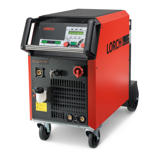
Page 4: Machine Elements
Machine elements Machine elements 27 17 Fig. 1: Machine elements S/P “driveable” - 4 - 909.2710.1-06 02.20... - Page 5 Machine elements Fig. 2: Machine element S/P mobile Gas hose Connection socket ground cable Chain Ground cable Tray area Connection socket electrode holder Mains plug Air intake Ground clamp Socket remote control (optional) Main switch Coolant filling nozzle (optional) Transport rollers Coolant return (optional) Socket for WUK 5 cooling system Coolant flow (optional)
-
Page 6: Safety Precautions
Norms IEC 60974-4 In-service inspection and testing Testing Lorch machines according to IEC 60974-4 – it is not necessary to disconnect any components of the power unit for the test – it is recommended to disconnect the torch at water cooled machines –... -
Page 7: Inverter Principle
80 kHz. This allows a very small construction of the welding transformer, because it‘s driven at this high frequency. The basic structure of a welding inverter is always the same at Lorch power sources: – mains filter –... -
Page 8: Machine Wiring Diagrams
Machine Wiring Diagrams Machine Wiring Diagrams L1 L2 0.42 0.20 X10/2 0.400 X10/1 X4/1 X4/2 X26/1 X8/1 ~1 ~2 ~3 X26/4 X8/2 +VCC CAN_L X8/3 CAN_H X8/4 X18/1 Start / Stop X18/2 +10VDC X18/3 0-10VDC X18/4 X18/5 X18/6 Ken. extern external X18/7 2 takt... - Page 9 Machine Wiring Diagrams L1 L2 0.42 F8*² XP/1 0.20 M4*² XP/3 0.230 X10/2 0.400 X10/1 A1*² T1*² F4*² 0.230 F3*² X6/3 M8-10* X4/1 X4/2 X6/1 XL/2 X13/1 X26/1 M5-7 XL/1 X26/4 X13/2 X8/1 +VCC X8/2 CAN_L X8/3 CAN_H X8/4 X18/1 Start / Stop X18/2 +10VDC...
- Page 10 Machine Wiring Diagrams - 10 - 909.2710.1-06 02.20...
- Page 11 Machine Wiring Diagrams 02.20 909.2710.1-06 - 11 -...
-
Page 12: Common Logic Functions
Tab. 1: Common logic functions Front panels Front panel P-Synergic / S-Pulse / S-SpeedPulse 3.0 Fig. 4: Front panel S 3.0 Front panel functions S/P Gas test – press the buttons “arrow up” [1] and “gas type“ (+) [2] at the same time –... - Page 13 Front panels Master Reset – press the buttons “arrow up” [1] and “Mode” [3] together for about five sec. – the display shows “Master Reset“ – the machine is reset completely to factory settings !!! CAUTION !!! all Tiptronic jobs are deleted after a Master Reset! Before a Master reset is done, it is important to check if Tiptronic jobs are present on the ma- chine.
-
Page 14: Front Panel P-Basic
Front panels Front panel P-basic Quatro Hold m/min Fig. 5: Front panel P-Basic Gas test – keep the torch trigger pressed – switch on the machine with the pressed trigger switch – the gas valve is switched on for 30 sec. Pump test –... -
Page 15: Pc-Boards
Pc-Boards Pc-Boards Pc-board MAPRO05 The pc-board MAPRO05 is responsible for the welding sequence and is managing the process control of the S- and P-series. (MAPRO = MAster-PROcess) Functions – Logicfunctions of the welding process – generating and monitoring supply voltages –... - Page 16 Pc-Boards Picture pc-board MAPRO05 LED5 LED2 LED4 LED6 LED3 Master Master 3,3V LED2 LED5 LED1 LED4 LED6 Fig. 6: pc-board MAPRO05 - 16 - 909.2710.1-06 02.20...
- Page 17 Pc-Boards DIP switch It is possible to program the DSP (Process) via a serial port (RS232 at connector X23). To set the proces- sor into programming mode, the DIP switches 1, 2 and 3 must be set to “ON”. All details about the serial programming is given in the operating manual “LorchInstall”...
- Page 18 Pc-Boards Overview connectors MAPRO05 Connector designation connector to power uint 1 connector control transformer (supply of pc-board) connector to pc-baord DS-ERW (only used at machines with two wire feed units) connector to power uint 2 connector to Interpass hose package 230V supply fans/cooling unit (from control transformer) connector fan group 1 (230V AC) LorchNet connector (CAN bus)
- Page 19 Pc-Boards 02.20 909.2710.1-06 - 19 -...
-
Page 20: Pc-Board Dmr
Pc-Boards Pc-board DMR The pc-board DMR is the wire feed motor control of the machine. Functions – control and monitoring wire feed motor – driving solenoid valve – control and monitoring of operating elements (DS20BF, PowerMaster, torch button) – monitoring wire inching button –... - Page 21 Pc-Boards Measuring points measuring designation result point 5V internal supply voltage X5-1 +5V DC X5-3 24V internal supply voltage X8-8 +24V DC X8-1 60V Motor supply voltage X8-5 +60V DC X8-6 Tab. 8: Measuring points DMR Overview connectors DMR connector designation torch trigger switch front panel...
-
Page 22: Pc-Board Pp90R
Pc-Boards Pc-board PP90R The pc-board PP90R is an analog control PCB for a PushPull torch. It is optional and can be retrofitted into existing, compact machines and wire feeders. It is connected to the pc-board DMR. Functions – supply for PushPull motor Meauring points measuring designation... -
Page 23: Pc-Board Dmrpp04
Pc-Boards Pc-board DMRPP04 The pc-board DMRPP04 is the (digital) control board to use a Lorch Push-Pull torch (optional). It is also necessary for the use of an intermediate feeder or for the NanoFeeder. If a digital PushPull shall be retrofitted into an existing machine, the pc-board DMR is replaced by the DMRPP04. - Page 24 Pc-Boards Picture pc-board DMRPP04 LED2 DIP S1 LED1 LED3 LED3 LED1 LED2 X11 X10 Fig. 11: Pc-board DMRPP04 - 24 - 909.2710.1-06 02.20...
- Page 25 Pc-Boards Overview connectors DMRPP04 connector designation torch trigger switch front panel volt/amp display wire inch button tacho wire feed motor solenoid valve control cable (Interpass hose package) wire inch and retract button wire feed motor “-” (minus) wire feed motor “+” (plus) welding potential (PowerMaster signal compensation) control cable PushPull flat ribbon connector motor wires...
-
Page 26: Pc-Board Zvp
Pc-Boards Configuration Intermediate Feeder When using an intermediate feeder, a stronger control transformer (655.8031.0) is used in the power source to provide enough power for the intermediate unit. This is done via an additional pc-board ZVP. Detailed information is given in the mounting instruction “Digital PushPull with auxiliary drive“ (E00.0320.1). Please note!: the first (“rear”) DMRPP04 pc-board requires special software (special firmware), the DMRPP04 pc-board in the intermediate feeder (“front”) has the standard PushPull firmware. - Page 27 Pc-Boards Schematic Fig. 14: Schematic pc-board ZVP connector designation control cable to MAPRO (X5) control cable to DMRPP +60V DC connection (input) 42V AC control transformer parallel connection to DMRPP Tab. 15: connections pc-board ZVP 02.20 909.2710.1-06 - 27 -...
-
Page 28: Pc-Board Ds20Bf
Pc-Boards Pc-board DS20BF The pc-board DS20BF is the front panel with all buttons, rotary impulse encoder and all displays. Functions – operating/setup the machine – display of parameters and malfunction codes Picture pc-board DS20BF LED11 LED10 LED5 LED6 LED7 LED8 LED14 LED16 LED15... -
Page 29: Pc-Board Ds21Bf
Pc-Boards Pc-board DS21BF LED5 LED6 LED7 LED8 LED11 LED13 LED12 LED1 LED10 LED14 LED15 LED2 LED3 LED4 LED9 Fig. 16: Pc-board DS21BF Pc-board DS22BF LED11 LED10 Fig. 17: Pc-board DS22BF 02.20 909.2710.1-06 - 29 -... -
Page 30: Pc-Board Mat-Bf
Pc-Boards Pc-board MAT-BF The pc-board MAT-BF is the front panel of the P-Basic machines. Fig. 18: Pc-board MAT-BF Front panel test function The display test at the P-Basic machines is activated by pressing the two outer buttons (mode TA1 and main parameter TA4). - 30 - 909.2710.1-06 02.20... -
Page 31: Pc-Board Ds-Va
Pc-Boards 7.10 Pc-board DS-VA The pc-board DS-VA is the digital volt and ampere display of the machine. Functions – display nominal and actual values of welding voltage and welding current – hold-function of the last welding values – displaying malfunction codes Picture pc-board DS-VA LED41 Fig. -
Page 32: Pc-Board Dcdr21 / Dcdr23
Pc-Boards 7.11 Pc-board DCDR21 / DCDR23 The pc-board DCDR21 is the primary driver board of the S5 and S8 / P4500 and P5500. The pc-board DCDR23 is the primary driver board of the S3 and P3x0 mobile. Functions – encoding power unit –... - Page 33 Pc-Boards Picture pc-board DCDR2x D00.0050.6-02 LED6 UZmin LED6 LED4 LED4 UZmax LED1 LED2 LED2 drv low LED1 ovr cur LED5 LED5 drv hi Fig. 21: Pc-board DCDR2x T=MOSFET (power transistor) D=diode !!! CAUTION !!! at all positions where cables are attached, the longer screws are used (A+ A- +UZ -UZ).
- Page 34 Pc-Boards Overview connectors pc-board DCDR connector designation flat ribbon cable to pc-board MAPRO05 connection to current sensor and pc-board PWRUP connection temperature sensor Tab. 19: Connectors DCDR PWM-Driver The pc-baord DCDR is the primary driver board for the transformer. It is a classical half bridge design. The supply is provided via pins 1, 2 and 3 of the flat ribbon cable and the PWM signals (PWM = Pulse Width Modulation) for driving the MOSFETs are at pin 5 (low side) and pin 6 (high side).
-
Page 35: Pc-Board Dk-Pwrup / Dk-Pwrup02
Pc-Boards 7.12 Pc-board DK-PWRUP / DK-PWRUP02 The pc-board DK-PWRUP is the charge-up control of the S3 and P3500. Depending on the type of the water pump or the application, the DK-PWRUP or the DK-PWRUP02 is used. cooling unit DK-PWRUP DK-PWRUP02 water pump standard “high pressure”... -
Page 36: Pc-Board Dk-Pwrup04Dkl / Dk-Pwrup05-Dkl
Pc-Boards 7.13 Pc-board DK-PWRUP04DKL / DK-PWRUP05-DKL The pc-board DK-PWRUP is the charge-up control of the S5, S8 and P4500, P5500. Depending on the type of the water pump or the application, the DK-PWRUP04 or the DK-PWRUP05 is used. cooling unit DK-PWRUP04DKL DK-PWRUP05-DKL water pump... -
Page 37: Pc-Board Dp-S3Nefi
Pc-Boards 7.14 Pc-board DP-S3NEFI The pc-board S3NEFI is the mains filter board and power-up of the S3 mobile and P3000 mobile. Functions – mains filter – limitation of inrush-current when charging up the capacitors on pc-board DCDR – supply for control transformer Measuring points measuring designation... - Page 38 Pc-Boards Power-up cycle After switching on the machine with the mains switch, the capacitors on the DCDR pcb are charged up first. These capacitors are buffering the bus voltage (rectified mains voltage). The input current during charge up can be very high and must be limited to prevent the mains fuses to break. The current limitation is made by the PWRUP pcb, where each phase is conducted via resistors to the mains rectifier.
-
Page 39: Pc-Board Dk-Glcl3
Pc-Boards 7.15 Pc-board DK-GLCL3 The pc-board DK-GLCL3 is for connecting/wiring the secondary rectifier diodes. Functions – connecting diodes – impulse smoothng – diode protection Picture pc-board DK-GLCL3 Fig. 27: Pc-board DK-GLCL3 Schematic Fig. 28: schematic welding rectifier 02.20 909.2710.1-06 - 39 -... -
Page 40: Pc-Board Dp-Ufi-Bo
Pc-Boards 7.16 Pc-board DP-UFI-BO The pc-board DP-UFI-BO is a filter circuit for meassuring the output voltage. Functions – low-pass filter for measuring output voltage 650.5311.x DP-UFI-BO RP393/2 D00.0107.2-00 Picture pc-board DP-UFI-BO Fig. 29: Pc-board DP-UFI-BO 7.17 Pc-board DP-EMV The pc-board DP-EMV is a emc-filter circuit for the compliance with emc regulations. Functions –... -
Page 41: Pc-Board Ds-Erw
Pc-Boards 7.18 Pc-board DS-ERW The pc-board DS-ERW is an extension board for machines with additional wire feeder (AB or BB version). Functions – switching between wire feeder 1 / wire feeder 2 – driving solenoid valve – driving water valves LEDs state meaning... - Page 42 Pc-Boards Schematic DMR1 DMR2 X7-1 X7-2 DS-ERW X8-1 X8-2 MAPRO In addition to the two DMR boards, the water valves are also connected the DS-ERW. Depending on the active torch (feed one or two), the water cooling circuit is also switched over. - 42 - 909.2710.1-06 02.20...
-
Page 43: Pc-Board Tc21
Pc-Boards 7.19 Pc-board TC21 The pc-board TC21 is the control board used inside the PowerMaster torches and in the hand remote con- trol RC20. It is used to set welding parameters. The communication is done via the torch trigger wires (PowerMaster torch) in the central connector (bi- directional, single-wire communication), or via the start-contact wires of the remote control socket (RC20). -
Page 44: Electrical Components
Electrical Components Electrical Components Current Sensor VAC The current sensor is used to measure the weldng current. Measuring points measuring designation result point supply voltage X1-1 +15V DC X1-2 -15V DC X1-4 sensor output X1-3 output current signal 1:2000) Tab. 27: Measuring point current sensor VAC Picture current sensor VAC Fig. - Page 45 Electrical Components New VAC position With the release of the software version 3.05 on 29.03.2018 the ignition behaviour of some welding char- acteristics has been improved. As a result, the magnetic field of the welding inductor also increases. This stronger magnetic field also affected the current sensor VAC, which was mounted relatively close to the welding choke, and sporadically there were false measurings.
-
Page 46: Control Transformer
Electrical Components Control transformer Depending on the machine configuration, different control transformers are used. control transformer useage 655.8021.0 S3, S5, S8 / P3500, P4500, P5500 with standard water pump 655.8023.0 S3 mobile / P3000 mobile 655.8031.0 S3, S5, S8 / P3500, P4500, P5500 with intermediate feeder 655.8037.0 S3, S5, S8 / P3500, P4500, P5500 with water pump “high pressure”... -
Page 47: Tig Option
Electrical Components TIG Option The TIG mode can be retrofit into all S- and P- machines. The retrofit kit contains all necessary parts like a additional solenoid valve and a TIG control socket. The TIG function must be activated first, before the mode can be selected via the mode button at the front panel (see also “9.14 Service Codes”... -
Page 48: Troubleshooting
Troubleshooting Troubleshooting Monitoring temperature The temperature of the heat sink is constantly monitored via a temperaure sensor. This sensor is a tem- perature dependent resistor (NTC = negative temperature coefficient). The higher the temperature, the lower the resistance value of the sensor. Schematic DP-MAPRO +3.3V... -
Page 49: Supply Voltages
Troubleshooting Supply voltages All internal supply voltages are generated and monitored on the pc-board MAPRO05. The basic supply is coming from the control transformer. Schematic Fig. 39: Supply voltages Different supply voltages are monitored by the Microcontroller (Master) and the DSP (Process). If the 24V drops below 17V the machine will stop and displays E14 (Op. -
Page 50: Monitoring Welding Current
Troubleshooting Monitoring welding current The welding current is measured via a separate current sensor (VAC). The current is monitored by the Microcontroller (Master) and the DSP (Process) independantly from each other. Schematic MAPRO +3.3V DCDRV +15V X2 / 3 X1 / 16 X2 / 2 X1 / 15 MASTER... -
Page 51: Pe-Protection / Gas Pressure Switch
Troubleshooting PE-protection / gas pressure switch All machines of the S- and P-Relaunch series have a build-in PE protection by standard. As soon as a cur- rent >15A is flowing via the PE (protective earth) wire of the mains cable, the Reed-contact opens and the machine stops with the code E04-01 (Stop/peripherals error). -
Page 52: Cooling Unit
Troubleshooting Cooling unit At watercooled machines, the flowrate of the coolant is measured in the return flow. The flowmeter output is a digital signal where it’s frequency is proportional to the flowrate. The higher the flowrate, the higher the frequency. If the flowrate is below 0.3 liter per minute, the machines will stop and dislays E05 (cooling system error). - Page 53 Troubleshooting Flow meter The most common cause of a cooling water fault “E05” is a dirty flow meter. Regular cleaning of the com- plete cooling circuit (torch, intermediate hose package, internal hoses, cooler) is recommended. Depend- ing on the degree of pollution, the coolant tank should be completely washed out, as dirt can accumulate at the bottom of the tank over time.
- Page 54 Troubleshooting Cooling unit versions The machines of the S- and P-Relaunch series can be ordered with different cooling units. Depending on the customers needs, he can choose between three versions: control fuse version pump transformer PWRUP standard standard standard 2 x 4A 665.5571.0 655.8021.0 slow...
-
Page 55: Monitoring Output Voltage
Troubleshooting Monitoring output voltage The output voltage is conducted via a low pass filter (pc-board DP-UFI-BO) to the MAPRO pcb. The voltage is measured by the Master as well as the Process. Schematic If the Master is measuring a voltage >100V, the machine will stop and displays E06 (secondary overvolt- age). -
Page 56: Monitoring Wire Feed Motor
Troubleshooting Monitoring wire feed motor The pc-board DMR has it‘s own microcontroller which is responsible for driving, controlling and monitoring the wire feed motor. Schematic The current consumption and the tacho signal of the motor are monitored by the microcontroller. If the current consumption of the motor is too high (e.g. - Page 57 Troubleshooting Schematic DMRPP04 Schweiß- potential DMRPP-C Amphenol 17+PE Drahteinlauf +24V Kaltdraht- Sensor Gas- Ausblaß- Draht- Draht- Lüfer Drahtende- Gastest ventil ventil rückzug einlauf Sensor Gastest Brenner- interface data Kollisionsschutz Kollisionsschutz analog Eingang +12V +12V +10V analog in +24V +24V ext. analog digital2 PushPull...
-
Page 58: Remote Control
Troubleshooting Remote control The remote control interface is for connecting a hand or foot remote control. It is also possible to use the interface for a small automation application. In case of “inpermissible“ short circuits between the connector pins of the interface, the machine will stop and displays E11 (remote control conn.). -
Page 59: Monitoring Primary Input Current
Troubleshooting Monitoring primary input current The input current of the power units is monitored at the DCDR pcb. The current that is flowing through the primary coils of the welding transformer is measured with an internal current sensor. As soon as the cur- rent is exceeding the maximum value, the CPLD (= Complex Programmable Logic Device) on the MAPRO shuts down the power unit immediately. -
Page 60: Monitoring Bus Voltage
Troubleshooting 9.10 Monitoring bus voltage The bus voltage is monitored by the DSP (Process) directly. As soon as the bus voltage is too low or too high, the machine will stop and displays the corresponding error message: E22 : Mains undervoltage 1 E23 : Mains overvoltage E30 : Mains undervoltage 2 Should the mains voltage be too low at both power units (at S5 or S8 / P4500 or P5500), only the error... -
Page 61: Encoding Power Units
Troubleshooting 9.11 Encoding power units During the initialisation of the machine (switching on), the MAPRO pcb is detecting what power units are connected. The identification of the power units is made by a DIP switch at the DCDR pcbs. Should the MAPRO detect that the configuration is not valid, it will stop and displays E25 (Power module detection). -
Page 62: Testing Mosfets
Troubleshooting 9.12 Testing MOSFETs MOSFET / IGBT - Test 9V Batterie benutzen, um die Drain-Source Strecke einzuschalten 9V Batterie 9V battery Drain-Source Strecke ist niederohmig Kurzschluss zwischen Gate und Source um Drain-Source Strecke „auszuschalten“ Drain-Source Strecke ist hochohmig 9.13 Inside diagram diodes - 62 - 909.2710.1-06 02.20... -
Page 63: Service Codes
Troubleshooting 9.14 Service Codes Via menu Extras, Lock function special Service codes can be entered to enanble or disable different func- tions. code function displayed message reset the three-digit code of the lock function to “000” Code = 0 activate TIG mode selection TIG mode On deactivate TIG mode selection TIG mode Off... -
Page 64: Malfunction Codes
Troubleshooting 9.15 Malfunction Codes code designation reason removal E 01 Thermal overload thermal sensor of power unit meas- let machine cool down in standby (*1) ures a too high temperature see page 48 for details E 02 Mains overvoltage mains voltage too high check mains voltage and control internal 24V supply >... - Page 65 Troubleshooting code designation reason removal – check PushPull-torch and -motor E 08 M04 Motor 2 overcurrent PushPull-motor draws too much cur- (only at DMRPP) rent – check motor current (*4) M05 Tachometer motor 1 – tacho signal of wire feed motor is –...
- Page 66 #1 - #5 ware MAPRO – switch the machine off and on again – contact Lorch Service if necessary sub code #10 setting of DIP switch 4 does not check DIP switch 4 on MAPRO match to serial number of the ma-...
- Page 67 Troubleshooting code designation reason removal E 29 EEProm checksum error data in EEPROM memory faulty/cor- switch the machine off and on again, rupt exchange the MAPRO if necessary E 30 Mains undervoltage 2 power unit 2 detected a too low bus check mains voltage, mains rectifier, voltage pc-board PWRUP and DCDR...
- Page 68 Lorch Schweißtechnik GmbH Im Anwänder 24 - 26 D-71549 Auenwald Germany Tel. +49 7191 503-0 Fax +49 7191 503-199 info@lorch.eu www.lorch.eu...
Need help?
Do you have a question about the S-Pulse and is the answer not in the manual?
Questions and answers