Table of Contents
Advertisement
Sede Operativa
Via Toscana, 57/59 - 20090 - Buccinasco (MI)
Tel. +39-02-45713300 Fax +39-02-45713351 e-mail: info@siel.com www.siel.com
Siel Broadcast S.p.A
Via delle Acacie, 2/4 - 05018 Orvieto (TR) - Italy
Tel. +39-0763-393721 Fax +39-0763-390752 e-mail: info@sieltelevision.com
C.F.e P. IVA IT 05305970963 Cap.Soc. € 2.040.000,00 Int. Vers.
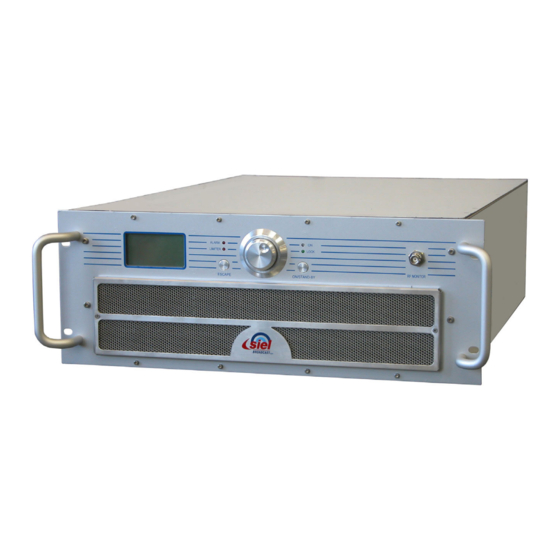
FM super-compact transmitter series
User and maintenance manual
Version 1.8
QUALITY SYSTEM
THE INTERNATIONAL
ISO 9001:2001
CERTIFICATION NETWORK
CERTIFICATE n. 9110.SIBR
REGISTRATION n. IT-61344
Advertisement
Table of Contents

Summary of Contents for Siel EXC-GT Series
- Page 1 Sede Operativa Via Toscana, 57/59 - 20090 - Buccinasco (MI) Tel. +39-02-45713300 Fax +39-02-45713351 e-mail: info@siel.com www.siel.com FM super-compact transmitter series User and maintenance manual Version 1.8 Siel Broadcast S.p.A Via delle Acacie, 2/4 - 05018 Orvieto (TR) - Italy Tel.
- Page 2 We used the utmost care in making a complete manual with detailed, precise, and updated information; however, the contents herein cannot be regarded as binding towards our company. SIEL, in their constant commitment to improve the quality of their products, reserve the right to vary the device’s technical features without prior notice. For updates, please visit our web-site www.siel.com...
- Page 3 EXC-GT – FM super-compact transmitter series Contents .......................... 5 NTRODUCTION !........................... 6 AFETY FIRST Symbols used ..........................6 Warnings ............................6 .................... 7 IEL PRODUCTS AND VALUE ADDED Full conformity to EC regulations ....................7 Quality in series manufacturing..................... 7 Overdesigning for performance.....................
- Page 4 EXC-GT – FM super-compact transmitter series ........... 52 LECTRICAL MECHANICAL DIAGRAMS AND PARTS LOCATION User’s manual – Page 4 of 98...
- Page 5 EXC-GT series the best offered on the market today. The transmitters in the EXC-GT series are available ranging from 30 W (for common uses, such as an exciter) to 4 KW, ideal for N+1 systems and as a spare transmitter.
- Page 6 IMPORTANT: Improper use or installation of this device could cause serious damage to objects and people alike. Therefore, it is essential to rely on an installer who has been previously authorized or approved by Siel, or by our local representative, and that both the user and the installer read the entire manual before carrying out any operation.
- Page 7 Siel is particularly careful about guaranteeing its clients conformity to regulations. To this end, after having taken measurements during the research phase, Siel uses a certified laboratory and an international certification body (Rasek) to certify the full conformity of its products based on measurements taken according to regulations.
- Page 8 D E N T I F Y I N G Y O U R M O D E L The EXC-GT Series family of transmitters has characteristics common to all of the models (for example, the command menu, the primary controls, the primary connection inputs, etc.). However, the range of models is in continual evolution, and each model is distinguished by a different transmission power and by characteristics specific to the series, or by optional characteristics that make it unique.
- Page 9 O M M A N D S A N D I N P U T S The primary commands and connections for the EXC-GT Series are common to all the models. However, each version has been created with a different unit rack and may be equipped with different functions and connections. This section allows you to identify your device and the locations of its available commands and inputs.
- Page 10 EXC-GT – FM super-compact transmitter series 5.1.b Model 2 Front Rear User’s manual – Page 10 of 98...
- Page 11 EXC-GT – FM super-compact transmitter series 5.1.c Model 3 Front Rear User’s manual – Page 11 of 98...
- Page 12 EXC-GT – FM super-compact transmitter series 5.1.d Model 4 Front Rear User’s manual – Page 12 of 98...
- Page 13 EXC-GT – FM super-compact transmitter series 5.1.e Model 5 Front Rear User’s manual – Page 13 of 98...
- Page 14 EXC-GT – FM super-compact transmitter series List of commands and inputs The commands and inputs that, according to your model, may be available on the device are listed below: Control panel – allows the user to set device functions, and to view and set operating parameters. It is composed of the following: Liquid crystal display (LCD) –...
- Page 15 EXC-GT – FM super-compact transmitter series [16] AUX – auxiliary modulating channel input (RDS/SCA) at low frequency on a 20-100 KHz band (BNC-type unbalanced connector with grounding shield) for connection to an RDS encoder. For details, see 7.9. [17] MPX – externally created broadband stereo composite modulating signal input (BNC-type unbalanced connector with grounding shield).
- Page 16 Should doubts or technical problems arise during the installation procedure, it is strongly recommended that you contact SIEL or a local agent/dealer. Should technical problems or doubts of any kind arise during installation, SIEL would be happy to provide qualified technical assistance. Technical intervention by personnel not authorized by Siel should not be performed.
- Page 17 In such cases, it is advisable, if not indispensable, to install a protector, an insulating transformer, or possibly an electromechanical mains voltage regulator. Upon request, SIEL can provide all of these accessories. Even though the mains regulator allows for a wide incoming voltage range, it is important to avoid operating using high impedance mains lines in proximity to the lowest permitted AC limit: if the line falls below a given value while fully loaded, the control circuit for the lowest AC limit may trigger a very dangerous oscillating on/off cycle.
- Page 18 EXC-GT – FM super-compact transmitter series The MPX connector is internally connected in parallel to the RIGHT connector. As such, if the MPX connector is in use, the simultaneous connection of signals to the LEFT and RIGHT connectors is not possible. Again in this case, the highest impedance position is 5 KOhm.
- Page 19 EXC-GT – FM super-compact transmitter series to suitable connectors, usually a female DB9 or DB25 on the PC port and a male DB9 connector to the transmitter. The applicable communication software is also required. Never connect the cable if the PC or transmitter are turned on. User’s manual –...
- Page 20 Connection to LEFT, RIGHT, or MPX modulation connectors The EXC-GT Series supports both balanced and unbalanced audio signals according to the connection that is made in the three LEFT and RIGHT XLR connector contacts. The input impedance for these contacts is pre-set at the factory at 10 KOhm resistivity (5 KOhm for unbalanced connections), which can be decreased to 600 Ohm if necessary, as explained further ahead.
- Page 21 EXC-GT – FM super-compact transmitter series The MPX connector is internally connected in parallel to the RIGHT connector. As such, if the MPX connector is in use, the simultaneous connection of signals to the LEFT and RIGHT connectors is not possible. In such case, the highest impedance position is 5 KOhm.
- Page 22 EXC-GT – FM super-compact transmitter series The input impedance is easily set using the JP1 e JP2 jumpers found on the input card, immediately after the input connectors as illustrated in the design. The selectable impedance values are serigraphed on the printed circuit board. Place the top cover back on the transmitter, ensuring that all the screws are correctly screwed into place.
- Page 23 Turn on the device via the rear power switch ( section 5.2 ref. [5]). For a few seconds, the Siel logo will appear on the full screen; after this, the default screen will be displayed ( section 10.1); the bottom of the default screen will show the two...
- Page 24 EXC-GT – FM super-compact transmitter series 8.1.b Operating frequency Ensure that the FREQUENCY sub-menu is selected; otherwise, turn the knob to select it. Press the knob to access the sub-menu. The following screen will appear ( section 10.3.a): Ensure that the EDIT option is selected; otherwise, turn the knob to select it, then press to confirm. A value will be indicated after Step (frequency steps).
- Page 25 EXC-GT – FM super-compact transmitter series Ensure that the EDIT option is selected; otherwise, turn the knob to select it, then press to confirm. A value will be indicated after Nom. Input, normally pre-defined at +6.0 dBm. Turn the knob to adjust the value based on the modulation level used. The peak deviation indicated by Mpx, expressed in KHz, will consequently be changed.
- Page 26 EXC-GT – FM super-compact transmitter series Ensure that the EDIT option is selected; otherwise, turn the knob to select it, then press to confirm. A value will be indicated after Mode. This indicator is normally followed by the operating mode (mono, stereo, mono L+R, or Mpx).
- Page 27 If you leave the device in the main SETUP menu, after a period, the timer will automatically select the STATUS sub-menu under the main VIEW menu in order to avoid programming accidental settings. Siel hopes you enjoy working with your device, and would like to remind you that they are always available for further information or to resolve specific problems.
- Page 28 EXC-GT – FM super-compact transmitter series when the ON LED changes from green to yellow. To perform the reverse operation, press the ON/STAND-BY button again. The ON LED will light up in green. 8.1.k Turning off the transmitter To completely deactivate the device (for maintenance, etc.), we recommend that you first put it on stand-by, as described above, and then completely turn off the device via the general power switch ( section 5.2 ref.
- Page 29 EXC-GT – FM super-compact transmitter series E N U A N D N A V I G A T I O N C O M M A N D S To view the device’s operating parameters, and to set parameters according to your requirements, you will need to navigate the commands menu shown on the LCD display.
- Page 30 EXC-GT – FM super-compact transmitter series Turn the knob to select the desired sub-menu, then confirm by briefly pressing the knob. In the example below, the screen for the FREQUENCY sub-menu is shown. At this point, depending on the main menu that you have accessed, various options may be available. Each option is explained in detail in the following chapter, and a brief overview is provided below: VIEW menu –...
- Page 31 EXC-GT – FM super-compact transmitter series 10 D E S C R I P T I O N O F T H E M E N U S The following menu descriptions refer to software version 1.2.3. Menus for higher-powered transmitters (approximately 1500 W or more) may include options for viewing additional parameters. 10.1 Default screen As soon as the device is turned on, the default screen will appear on the display, indicating the following information: indicates the transmitter model (in this example, EXC30GT).
- Page 32 EXC-GT – FM super-compact transmitter series STATUS sub-menu 10.2.a The screen for this sub-menu contains the following items: indicates the direct power currently delivered (in the example, 25.0 W). Dir. Power: Refl. Power: indicates the reflected power currently measured (in the example, 0.0 W). (multiplex) –...
- Page 33 EXC-GT – FM super-compact transmitter series The above example shows the standard level of the RDS signal (2 KHz), as well as the bar indicator, which shows the level graphically. Adjustments can be made to modulation of the auxiliary signal via the SETUP menu ( 10.3).
- Page 34 EXC-GT – FM super-compact transmitter series Frequency: indicates the operating frequency (in the example, 98.00 MHz). indicates , or mode (in the example, Mode: Mono Stereo Mono L+R Stereo Preemphasis: indicates the modulation preemphasis value (in the example, 50 microseconds). Elapsed hours: indicates the time elapsed since the device was first turned on in the factory (in the example, 1 hour).
- Page 35 EXC-GT – FM super-compact transmitter series If the device already has 100 events/alarms in its memory, a new event/alarm that occurs will cancel out the oldest recording so that the new event/alarm can be saved (FIFO). Via the SETUP menu, you can decide whether to activate/deactivate each alarm (e.g., low power, insufficient modulation, etc.), and set new detection thresholds ( section 10.3.l).
- Page 36 EXC-GT – FM super-compact transmitter series As you can see, the three pages allow you to access the following settings: FREQUENCY – frequency increment steps and operating frequency ( 10.3.a) – output power level ( 10.3.b) POWER MPX SENS – modulation sensitivity ( 10.3.c) AUX SENS –...
- Page 37 EXC-GT – FM super-compact transmitter series The display shows the following: – followed by the deviation value, expressed in KHz (in the example, 80.2 KHz) and in dB, in reference to a deviation of 75 KHz (0dB = 75 KHz) –...
- Page 38 EXC-GT – FM super-compact transmitter series described in section 8.1.e. When the limiter begins to intervene, the modulation distortion increases. As such, the modulation sensitivity should be adjusted ( section 10.3.c) so the limiter intervenes sporadically. Using this approach, its operation is generally imperceptible. 10.3.f MODE setting Used to define whether the transmitter operates in mono or stereo, and its preemphasis value.
- Page 39 EXC-GT – FM super-compact transmitter series The following parameters can be adjusted: – transmitter’s activation/deactivation mode. You can define whether this takes place via the front ON/STAND-BY button only (the Type ENABLE line is therefore deactivated), the rear line only (the front ON/STAND-BY button is deactivated), or using both commands (either the front button or the ENABLE line).
- Page 40 EXC-GT – FM super-compact transmitter series The display shows the following: Time – followed by the currently set time – followed by the currently set date Date Use of this menu is described in section 8.1.g It is important to correctly set the time and date; otherwise, the alarm history and various other functions will not operate correctly.
- Page 41 EXC-GT – FM super-compact transmitter series Turn the knob to select the second character, then press to confirm. The third character in the password will be highlighted. Turn the knob to select the third character, then press to confirm. The fourth character in the password will be highlighted. Turn the knob to select the fourth character, then press to confirm.
- Page 42 EXC-GT – FM super-compact transmitter series LOW RF POW Two parameters can be set from this screen: – if the output power falls below the percentage set here (in reference to the nominal value set using the command PreAl. Low Power outlined in section 10.3.b), a warning pre-alarm is issued by flashing the ALARM LED.
- Page 43 EXC-GT – FM super-compact transmitter series In the above example, if the synthesizer is unlocked for a Delay of 31 seconds, an alarm will be issued. To set the synthesizer unlock alarm: Ensure that the EDIT option is selected; otherwise, turn the knob to select it, then press to confirm. A value will be indicated after Delay.
- Page 44 EXC-GT – FM super-compact transmitter series The display will show the following parameters: – physical Media Access Control address for the internal network card. – static IP address for the internal network card. To set the IP address: Ensure that the EDIT option is selected; otherwise, turn the knob to select it, then press to confirm. The first number after IP will be highlighted.
- Page 45 IMPORTANT! Always note down the level 3 password and sore it in a safety place. Should you loose it, the total re- programming of the equipment or the CPU replacement at siel will be mandatory – with the related costs which this operation involves.
- Page 46 EXC-GT – FM super-compact transmitter series Select SET PASSWORD LEV 3 and change the password by following the procedure stated in par. 10.3.k. You can change the level 3 password, but not disable it, because its setting is always fixed to ON. User’s manual –...
- Page 47 Periodic overhaul After a few years of continuous service, it is advisable to have the device overhauled in our factory or in a specialized Siel laboratory, where its characteristics can be checked against the initial parameters. If necessary, regular maintenance operations can also be carried out at this time.
- Page 48 EXC-GT – FM super-compact transmitter series 12 T R O U B L ES H O O T I N G If all instructions set forth in the present manual are followed, RFB4005 will guarantee several years of perfect service. However, should problems arise, consult the present chapter before contacting the local authorized assistance point.
- Page 49 This section’s sole purpose is to provide general explanations about the device operation in order to simplify the maintenance by skilled personnel authorized by Siel. As already mentioned, no internal adjustments are required for normal operation. Tampering with the internal settings renders the warranty null and void and could seriously damage the equipment, compromising the guaranteed performance.
- Page 50 EXC-GT – FM super-compact transmitter series 14 T E C H N I C A L F E A T U R E S Frequency range ..................................87,5 ÷ 108 MHz FM modulation ............................75 KHz (adjustable) peak deviation Mono..................................180kF3E Stereo ..................................256kF3E Audio/MPX input level ........................
- Page 51 EXC-GT – FM super-compact transmitter series 15 I N D E X FREQUENCY; 36 Antenna; 17 Location of parts; 9 LIMITER; 37 Antenna output socket/flange; 14 Mains; 18 MODE; 38 MODEM; 45 Auxiliary modulation; 18 Maintenance; 47 MPX SENS; 36 Basic operations Modulation;...
- Page 52 EXC-GT – FM super-compact transmitter series 16 E L E C T R I C A L M E C H A N I C A L D I A G R A M S A N D P A R T S L O C A T I O N Figure 1 –...
- Page 53 Figure 44 – RFB 4005 Line Interface Board – CS37032 (E1149A) ..............96 User’s manual – Page 53 of 98...
- Page 54 Figure 1 – EXC30 Top view (open) EXC-GT – FM super-compact transmitter series User’s manual – Page 54 of 98...
- Page 55 Figure 2 – EXC30 General Wiring Diagram – E1161 EXC-GT – FM super-compact transmitter series User’s manual – Page 55 of 98...
- Page 56 Figure 3 – Control Mainboard/1 (LF and Mainboard section) – E0837CS (CS30111B) EXC-GT – FM super-compact transmitter series User’s manual – Page 56 of 98...
- Page 57 Figure 4 – Control Mainboard/2 (LF Process Section) – E0837CS (CS30111B) EXC-GT – FM super-compact transmitter series User’s manual – Page 57 of 98...
- Page 58 Figure 5 – LF and Mainboard – CS30111B (E0837CS) EXC-GT – FM super-compact transmitter series User’s manual – Page 58 of 98...
- Page 59 Figure 6 – CPU Controller Board 1/3 – E1148 (CS36121A) EXC-GT – FM super-compact transmitter series User’s manual – Page 59 of 98...
- Page 60 Figure 7 – CPU Controller Board 2/3 – E1148 (CS36121A) EXC-GT – FM super-compact transmitter series User’s manual – Page 60 of 98...
- Page 61 Figure 8 – CPU Controller Board 3/3 – E1148 (CS36121A) EXC-GT – FM super-compact transmitter series User’s manual – Page 61 of 98...
- Page 62 Figure 9 – CPU Controller Board – CS36121A (E1148) EXC-GT – FM super-compact transmitter series User’s manual – Page 62 of 98...
- Page 63 Figure 10 – Keyboard and Display Board – E1157 (CS36072) EXC-GT – FM super-compact transmitter series User’s manual – Page 63 of 98...
- Page 64 Figure 11 – Keyboard and display Board – CS36072 (E1157) EXC-GT – FM super-compact transmitter series User’s manual – Page 64 of 98...
- Page 65 Figure 12 – FM Exciter Board – E0839m (CS29041) EXC-GT – FM super-compact transmitter series User’s manual – Page 65 of 98...
- Page 66 Figure 13 – FM Exciter Board – CS29041 (E0839m) EXC-GT – FM super-compact transmitter series User’s manual – Page 66 of 98...
- Page 67 Figure 14 – Power Amplifier Board – E1137 (CS36092C) EXC-GT – FM super-compact transmitter series User’s manual – Page 67 of 98...
- Page 68 Figure 15 – Power Amplifier Board – CS36092C (E1137) EXC-GT – FM super-compact transmitter series User’s manual – Page 68 of 98...
- Page 69 Figure 16 – Mains Input SMPS Board – E0840CS (CS29052A) EXC-GT – FM super-compact transmitter series User’s manual – Page 69 of 98...
- Page 70 Figure 17 – Mains Input SMPS Board – CS29052A (E0840CS) EXC-GT – FM super-compact transmitter series User’s manual – Page 70 of 98...
- Page 71 Figure 18 – Analog Input Board – E1124m EXC-GT – FM super-compact transmitter series User’s manual – Page 71 of 98...
- Page 72 Figure 19 – AES/EBU Digital Input Board – CS35041A (E1124m) EXC-GT – FM super-compact transmitter series User’s manual – Page 72 of 98...
- Page 73 Figure 20 – Stereo Encoder Board – E0868 (CS29121A) EXC-GT – FM super-compact transmitter series User’s manual – Page 73 of 98...
- Page 74 Figure 21 – Stereo Encoder Board – CS29121A (E0868) EXC-GT – FM super-compact transmitter series User’s manual – Page 74 of 98...
- Page 75 FORO 3M5 FORO 3M5 MIPW_GSM TS33 S0603 LMC7101 LDOE +VBB SYNC VINGSM REV. DATA AUTORE SIEL Sistemi Elettronici S.r.l. BCR142 S1206 +VDDAUX 10K 1% Via TOSCANA 57 22nF S1206 20090 BUCCINASCO (MI) 10nF 14 09 06 S. Corti 100nF 10nF...
- Page 76 Figure 23 – RS 485 Interface Board – E1171 (CS37111) Figure 24 – RS 485 Interface Board layout – CS37111 (E1171) Component side Rear side EXC-GT – FM super-compact transmitter series User’s manual – Page 76 of 98...
- Page 77 Figure 25 – EXC 120 – Vista dall’alto (aperto) EXC-GT – FM super-compact transmitter series User’s manual – Page 77 of 98...
- Page 78 Figure 26 – EXC 120 – General Wiring Diagram E1170 EXC-GT – FM super-compact transmitter series User’s manual – Page 78 of 98...
- Page 79 Figure 27 – Power Amplifier Board – E1156 (CS37051) EXC-GT – FM super-compact transmitter series User’s manual – Page 79 of 98...
- Page 80 Figure 28 – Power Amplifier Board – CS37051 (E1156) EXC-GT – FM super-compact transmitter series User’s manual – Page 80 of 98...
- Page 81 Figure 29 – Aux Power Supply Board – E1057 (CS34044) EXC-GT – FM super-compact transmitter series User’s manual – Page 81 of 98...
- Page 82 Figure 30 – Aux Power Supply Board – CS34044 (E1057) EXC-GT – FM super-compact transmitter series User’s manual – Page 82 of 98...
- Page 83 Figure 31 – EXC 705-1505 Power System – E1191 EXC-GT – FM super-compact transmitter series User’s manual – Page 83 of 98...
- Page 84 Figure 32 – EXC 705-1505 Low Level Wiring Diagram – E1192 EXC-GT – FM super-compact transmitter series User’s manual – Page 84 of 98...
- Page 85 Figure 33 – EXC 705-1505 RF Power Amplifier – E1193 EXC-GT – FM super-compact transmitter series User’s manual – Page 85 of 98...
- Page 86 Figure 34 – Power Supply Control – E1169 (CS37102) EXC-GT – FM super-compact transmitter series User’s manual – Page 86 of 98...
- Page 87 Figure 35 – Power Supply Control – CS37102 (E1169) EXC-GT – FM super-compact transmitter series User’s manual – Page 87 of 98...
- Page 88 Figure 36 – Driver Amplifier Board – E0927 (CS32049) EXC-GT – FM super-compact transmitter series User’s manual – Page 88 of 98...
- Page 89 Figure 37 – Driver Amplifier Board – CS32049 (E0927) EXC-GT – FM super-compact transmitter series User’s manual – Page 89 of 98...
- Page 90 Figure 38 – I/O Interface Board – E0911 (CS31111A) EXC-GT – FM super-compact transmitter series User’s manual – Page 90 of 98...
- Page 91 Figure 39 – I/O Interface Board – CS31111A (E0911) EXC-GT – FM super-compact transmitter series User’s manual – Page 91 of 98...
- Page 92 Figure 40 – EXC2505-4005 Power System – E1188 EXC-GT – FM super-compact transmitter series User’s manual – Page 92 of 98...
- Page 93 Figure 41 – EXC 2505-4005GT Low Level Wiring Diagram – E1189 EXC-GT – FM super-compact transmitter series User’s manual – Page 93 of 98...
- Page 94 Figure 42 – EXC 2505-4005GT RF Power Amplifier – E1190 EXC-GT – FM super-compact transmitter series User’s manual – Page 94 of 98...
- Page 95 Figure 43 – RFB 4005 Line Interface Board – E1149A (CS37032) EXC-GT – FM super-compact transmitter series User’s manual – Page 95 of 98...
- Page 96 Figure 44 – RFB 4005 Line Interface Board – CS37032 (E1149A) EXC-GT – FM super-compact transmitter series User’s manual – Page 96 of 98...
- Page 97 User Manual – Page 97 of 98...
- Page 98 User Manual – Page 98 of 98...
Need help?
Do you have a question about the EXC-GT Series and is the answer not in the manual?
Questions and answers