Table of Contents
Advertisement
Quick Links
Advertisement
Table of Contents

Related Manuals for Alienware Area-51 m7700


Summary of Contents for Alienware Area-51 m7700
- Page 3 Preface Notice The company reserves the right to revise this publication or to change its contents without notice. Infor- mation contained herein is for reference only and does not constitute a commitment on the part of the man- ufacturer or any subsequent vendor. They assume no responsibility or liability for any errors or inaccuracies that may appear in this publication nor are they in anyway responsible for any loss or damage resulting from the use (or misuse) of this publication.
-
Page 4: Fcc Statement
Preface FCC Statement (Federal Communications Commission) This equipment has been tested and found to comply with the limits for a Class B digital device, pursuant to Part 15 of the FCC Rules. These limits are designed to provide reasonable protection against harmful interference in a residential installation. -
Page 5: Important Safety Instructions
IMPORTANT SAFETY INSTRUCTIONS Follow basic safety precautions, including those listed below, to reduce the risk of fire, electric shock, and injury to persons when using any electrical equipment: Do not use this product near water, for example near a bath tub, wash bowl, kitchen sink or laundry tub, in a wet basement or near a swimming pool. -
Page 6: Instructions For Care And Operation
Preface Instructions for Care and Operation The notebook computer is quite rugged, but it can be damaged. To prevent this, follow these suggestions: Don’t drop it, or expose it to shock. If the computer falls, the case and the components could be dam- aged. - Page 7 Avoid interference. Keep the computer away from high capacity transformers, electric motors, and other strong magnetic fields. These can hinder proper performance and damage your data. Follow the proper working procedures for the computer. Shut the computer down properly and don’t forget to save your work.
-
Page 8: Power Safety
Preface Power Safety The computer has specific power requirements: • Only use a power adapter approved for use with this computer. • Your AC adapter may be designed for international travel but it still requires a Power Safety Warning Before you undertake •... -
Page 9: Battery Precautions
Battery Precautions • Only use batteries designed for this computer. The wrong battery type may explode, leak or damage the com- puter. • Do not continue to use a battery that has been dropped, or that appears damaged (e.g. bent or twisted) in any way. -
Page 10: Cleaning
Preface Cleaning Do not apply cleaner directly to the computer; use a soft clean cloth. Do not use volatile (petroleum distillates) or abrasive cleaners on any part of the computer. Servicing Do not attempt to service the computer yourself. Doing so may violate your warranty and expose you and the computer to electric shock. -
Page 11: Travel Considerations
Travel Considerations Packing As you get ready for your trip, run through this list to make sure the system is ready to go: Check that the battery pack and any spares are fully charged. Power off the computer and peripherals. Close the display panel and make sure it’s latched. - Page 12 Preface On the Road In addition to the general safety and maintenance suggestions in this preface, and Chapter 8: Troubleshoot- ing, keep these points in mind: Hand-carry the notebook - For security, don’t let it out of your sight. In some areas, computer theft is very common.
-
Page 13: Developing Good Work Habits
Developing Good Work Habits Developing good work habits is important if you need to work in front of the computer for long periods of time. Improper work habits can result in discomfort or serious injury from repetitive strain to your hands, wrists or other joints. - Page 14 Preface Lighting Proper lighting and comfortable display viewing angle can reduce eye strain and muscle fatigue in your neck and shoulders. • Position the display to avoid glare or reflections from overhead lighting or outside sources of light. • Keep the display screen clean and set the brightness and contrast to levels that allow you to see the screen clearly.
-
Page 15: Table Of Contents
Notice ...I FCC Statement ...II Instructions for Care and Operation ... IV Power Safety ... VI Battery Precautions ...VII Cleaning ... VIII Servicing ... VIII Travel Considerations ... IX Quick Start Guide Overview ...1-1 Advanced Users ...1-2 Beginners and Not-So-Advanced Users ...1-2 Warning Boxes ...1-2 Not Included ...1-2 System Software ...1-3... - Page 16 Preface Audio "DJ" CD Player ...2-12 Adding a Printer ...2-14 USB Printer ...2-14 Install Instructions: ...2-14 Parallel Printer ...2-14 Power Management Overview ...3-1 Advanced Configuration and Power Interface ...3-1 The Power Sources ...3-2 AC Adapter ...3-2 Battery ...3-2 Turning on the Computer ...3-3 Power Schemes ...3-4 System Power Options ...3-6 Hibernate Mode vs.
- Page 17 Module Drivers ...4-24 Wireless LAN (WinXP) ...4-24 WLAN & Bluetooth Combo (WinXP) ...4-24 TV Tuner (WinXP) ...4-24 PC Camera (WinXP) ...4-24 BIOS Utilities Overview ...5-1 The Power-On Self Test (POST) ...5-2 Failing the POST ...5-3 Fatal Errors ...5-3 Non-Fatal Errors ...5-3 The Setup Program ...5-4 Entering Setup ...5-4 Setup Screens ...5-5...
- Page 18 Preface Driver Installation ...7-5 Bluetooth/WLAN Combo Module ...7-6 Combo Module Bluetooth Driver Installation ...7-7 Combo Module WLAN Driver Installation ...7-8 TV Tuner Module Options ...7-9 AverMedia M102 Mini-PCI TV Tuner Module ..7-10 Installing the AverTV Utility Software ...7-10 Installing the InterVideo WinDVD 4 Software ..7-10 YUAN PVR Mini-PCI MPC622-MCE TV Tuner Module ...7-11 Installing the MPC622 Driver for...
- Page 19 Headphone-Out Jack ...A-5 Security Lock Slot ...A-5 NVIDIA Video Driver Controls NVIDIA Video Driver Installation ... B-1 NVIDIA Display Properties ... B-2 Display Devices ... B-6 Attaching Other Displays ... B-7 Display Modes ... B-9 Enabling TV Display ... B-10 ATI Video Driver Controls ATI Video Driver Installation ...
- Page 20 Preface XVIII...
-
Page 21: Chapter 1: Quick Start Guide
Chapter 1: Quick Start Guide Overview This Quick Start Guide is a brief introduction to the basic features of your computer, to navigating around the computer and to getting your system started. The remainder of the manual covers the following: •... -
Page 22: Advanced Users
Quick Start Guide Advanced Users If you are an advanced user you may skip over most of this Quick Start Guide. However you may find it useful to refer to “Drivers & Utilities” on page 4 - on page 6 - 1 in the User’s Manual. -
Page 23: System Software
System Software Your computer may already come with system software pre-installed. Where this is not the case, or where you are re-configuring your computer for a different system, you will find this manual refers to the following oper- ating systems: •... -
Page 24: System Startup
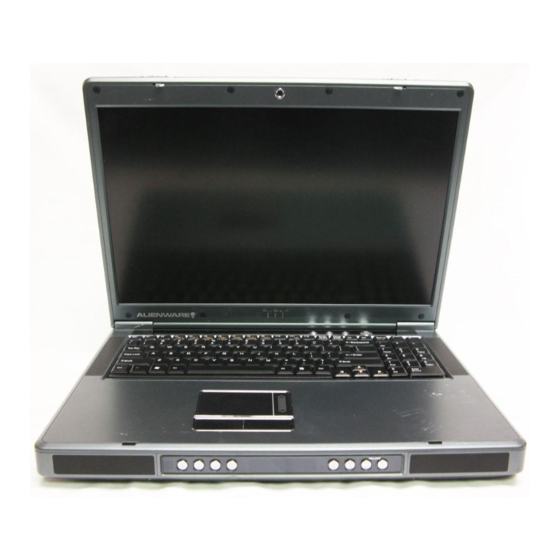
Quick Start Guide System Startup LCD Latches LED Power & Communication Indicators Figure 1 - 1 - Top Panel with LCD Closed Please note that you should always shut your computer down by choosing the Shut Down/Turn Off Computer command from the Start menu in Windows. -
Page 25: System Map: Top View With Lcd Panel Open
System Map: Top View with LCD Panel Open Wireless Device Operation Aboard Aircraft The use of any portable electronic transmission devices aboard aircraft usually prohibited. Make sure the mod- ule(s) are OFF if you are using computer aboard aircraft. The key combination Fn + F11 toggles power to the WLAN module, Fn + F12 to the Bluetooth... -
Page 26: Led Indicators
Quick Start Guide LED Indicators The two sets of LED indicators (LED Status Indica- tors and LED Power & Communication Indicators) on the computer display helpful information about the current status of the computer. Table 1 - 1 - LED Status Indicators Icon Color Green... -
Page 27: Ap-Key Buttons
AP-Key Buttons These buttons access the internet, e-mail or a user-de- fined application with one quick button press. Make sure you install the driver to enable the AP-Key Button functions (refer to “What to Install” on page 4 - Table 1 - 3 - AP-Key Buttons AP-Key Function Activate the Default E-mail Program... - Page 28 Quick Start Guide Table 1 - 4 - Function Keys Keys Description Function Key Fn + F3 Mute Toggle Fn + F4 Sleep Toggle Fn + F5 Decrease Audio Volume Fn + F6 Increase Audio Volume Fn + F7 Display Toggle Fn + F8 Decrease LCD Brightness Fn + F9...
-
Page 29: System Map: Front & Rear Views
System Map: Front & Rear Views The built-in standalone audio CD player gives you direct hardware control for audio CDs (MP3 compatible) when the computer is shut down, but has a working power source. To prevent your computer from overheating make sure nothing blocks the vent(s)/fan intake(s) while the computer is in use. -
Page 30: System Map: Left View
Quick Start Guide System Map: Left View Figure 1 - 5 Left View S-Video-Out Jack 4 * USB 2.0 Ports 2 * Mini-IEEE 1394a Port Line-In Jack S/PDIF-Out Jack Microphone-In Jack Headphone-Out Jack 10-in-1 Card Reader PC Card Slot 10. Infrared Transceiver (see page Mini-IEEE 1394a Both Mini-IEEE 1394a... -
Page 31: System Map: Right View
System Map: Right View Changing DVD Regional Codes Go to the Control Panel and double-click System > Hardware (tab), click Device Manager, then click the + next to DVD/CD-ROM drives. Double-click on the DVD-ROM device to bring up the Properties di- alogue box, and select the DVD Region (tab) to bring up the control panel to allow you to adjust the regional code (see... -
Page 32: System Map: Bottom View
Quick Start Guide System Map: Bottom View Figure 1 - 7 - Bottom View Battery Vent/Fan Intake Memory (RAM) Cover Hard Disk Cover Sub Woofer Video Card Cover CPU Cover Always completely discharge, then fully charge, a new battery before using it. Completely discharge and charge the battery at least once every 30 days or after about 20 partial discharges. -
Page 33: Windows Xp Start Menu & Control Panel
Quick Start Guide Windows XP Start Menu & Control Panel Most of the control panels, utilities and programs within Windows XP are accessed from the Start menu. When you install programs and utilities they will be installed on your hard disk drive, and a shortcut will usually be placed in the Start menu and/or the desktop. -
Page 34: Video Features
Quick Start Guide Video Features Video Driver Controls This computer features six different (NVIDIA GeForce Go 6800, NVIDIA GeForce Go 6800 Ultra, NVIDIA Quadro FX Go 1400, NVIDIA GeForce Go 7800 GTX, ATI Mobility Radeon X800 or ATI Mobility Rade- on X800 XT) PCI Express video card options (see You can switch display devices, and configure display options, from the Display Properties control panel in Windows as long as the appropriate video driver is installed. -
Page 35: Nvidia Display Properties
Quick Start Guide NVIDIA Display Properties ATI Display Properties Figure 1 - 9 - Display Properties Desktop Video Features 1 - 15... -
Page 36: Display Devices & Options
Quick Start Guide Display Devices & Options Besides the built-in LCD, you can also use an external VGA monitor (CRT)/external Flat Panel Display or TV as your display device. A VGA monitor/Flat Panel Display connects to the DVI-Out port, a TV to the S- Video-Out jack. -
Page 37: Power Management Features
Quick Start Guide Power Management Features The Power Options control panel in Windows (see page 13) allows you to configure power management features for your computer. You may conserve power through individual components such as the monitor or hard disk (by means of Power Schemes), or you may use either Standby or Hibernate mode to conserve power throughout the system (enable Hibernate support from the control panel as pictured in Figure 1 - 10). - Page 38 Concise User’s Guide 1 - 18...
-
Page 39: Storage Devices, Mouse, Audio & Printer
Storage Devices, Mouse, Audio & Printer Chapter 2: Storage Devices, Mouse, Audio & Printer Overview Read this chapter to learn more about the following main features and compo- nents of the computer: • The Hard Disk Drive • The Optical (CD/DVD) Device •... -
Page 40: Hard Disk Drive
Storage Devices, Mouse, Audio & Printer Power Safety Before attempting to access any of the inter- components your computer please ensure that the ma- chine is not connected to the AC power, and that the machine is turned off. Also ensure that all peripheral ca- bles, including phone lines, are disconnected... -
Page 41: Optical Device
Optical Device There is a bay for a 5.25" optical (CD/DVD) device (12.7mm height). The ac- tual device will depend on the model you purchased (see on page D - 4). The optical device is usually labeled “Drive D:” and may be used as a boot device if properly set in the BIOS 13). -
Page 42: Handling Cds Or Dvds
Storage Devices, Mouse, Audio & Printer CD Emergency Eject If you need to manually eject a CD (e.g. due to an unexpected power interruption) you may push the end of a straightened paper clip into emergency eject hole. However please do NOT use a sharpened pencil or similar object that may break... -
Page 43: Dvd Regional Codes
DVD Regional Codes To change the DVD regional codes see page 1 - DVD Regional Coding Geographical Location Region USA, Canada Western Europe, Japan, South Africa, Middle East & Egypt South-East Asia, Taiwan, South Korea, The Philippines, Indonesia, Hong Kong South &... -
Page 44: 10-In-1 Card Reader
Storage Devices, Mouse, Audio & Printer Operating System Installation Warning If you are installing an operating system (e.g. Windows XP), have a 10-in-1 Card Reader present, make sure to set the Card Reader option in the BIOS to “Disabled”. “Card Reader: (Advanced Menu)”... -
Page 45: Pc Card Slot
PC Card Slot The computer is equipped with a PCMCIA 3.3V/5V slot for one type II PC Card. Inserting and Removing PC Cards • Align the PC Card with the slot and push it in until it locks into place. •... -
Page 46: Touchpad And Buttons/Mouse
Storage Devices, Mouse, Audio & Printer Mouse Driver If you are using an ex- ternal mouse your op- erating system may be able to auto-configure your mouse during its installation or only ena- ble its basic functions. Be sure to check the device’s user docu- mentation for details. -
Page 47: Configuring The Infrared Settings For Fir
Configuring the Infrared Settings for FIR To configure your computer for Fast Infrared (FIR) communication follow these steps: Click Start, point to Settings and click Control Panel (or just click Start > Control Panel). Double-click Wireless Link (Printers and Other Hardware Category) icon. Click Hardware (tab), and click the Properties button, then click the Advanced (tab). -
Page 48: Audio Features
Storage Devices, Mouse, Audio & Printer Sound Volume Adjustment How high the sound volume can be set us- ing the volume control knob depends on the setting of the volume control within Win- dows. Click the Vol- icon taskbar to check the setting. -
Page 49: Channel Sound Support
Storage Devices, Mouse, Audio & Printer 8 Channel Sound Support If you wish to configure your system for 8 channel sound support, then the fol- lowing ports should be used as outputs. • Side Speaker Out - Connect to S/PDIF Out •... -
Page 50: Audio "Dj" Cd Player
Storage Devices, Mouse, Audio & Printer Disk Eject Warning Don’t try to eject a CD/ DVD while the system is accessing it. This may cause the system to “crash”. Stop the disk first then eject it, or press the stop but- ton twice. - Page 51 Audio "DJ" Power Button Previous Track Next Track Shuffle (loop, in order, shuffle) LED Display Play/Pause Stop (press twice to eject the CD/DVD) Volume Down Volume Up 10. Audio Format Indicator 11. Shuffle Mode Indicator 12. Track Indicator Note: The time will be displayed on the LED Display if set in the BIOS (see “Display Time on LED (Advanced Menu)”...
-
Page 52: Adding A Printer
Storage Devices, Mouse, Audio & Printer Parallel Printer After setting up the printer attach the paral- lel cable to the printer. Connect the printer’s parallel cable to the Parallel port. Turn ON the printer, then the computer. Windows will identify the printer and either load one of its own drivers or ask you to... -
Page 53: Chapter 3: Power Management
Chapter 3: Power Management Overview To conserve power, especially when using the battery, your computer uses the ACPI power management system. Power management conserves power by controlling individual components of the computer (the monitor and hard disk drive) or the whole system. This chapter covers: •... -
Page 54: The Power Sources
Power Management Power Button as Standby or Hibernate Button If you are using a fully ACPI-compliant (such as Windows XP) you can use the OS’s “Power Options” con- trol panel to set the power button to send the system into Stand- by or Hibernate mode (see your OS’s docu- mentation, or... -
Page 55: Turning On The Computer
Turning on the Computer Now you are ready to begin using your computer. To turn it on simply press the power button on the front panel. When the computer is on, you can use the power button as a Standby/Hiber- nate/Shutdown hot-key button when it is pressed for less than 4 seconds (pressing and holding the power button for longer than this will shut the com- puter down). -
Page 56: Power Schemes
Power Management Resuming Operation The system can re- sume from Monitor or Hard Disk Standby by pressing a key on the keyboard. Figure 3 - 1 Power Schemes 3 - 4 Power Schemes Power Schemes You can set your computer to conserve power through individual components by means of Power Schemes. - Page 57 Power Management Each Windows Power Scheme will also adjust the processor performance of your machine in order to save power. This is worth bearing in mind if you are experiencing any reduced performance (especially under DC/battery power). Choose the Home/Office Desk scheme for maximum performance when the computer is powered from an AC power source.
-
Page 58: System Power Options
Power Management System Power Options You can use the system power options to stop the computer’s operation and restart where you left off. This system features Standby and Hibernate sleep mode levels (Hibernate mode will need to be enabled by clicking the option in the Hibernate tab in the Power Options control panel - Figure 3 - 2 on page 3 -... -
Page 59: Standby
Standby Standby saves the least amount of power, but takes the shortest time to return to full operation. During Standby the hard disk is turned off, and the CPU is made to idle at its slowest speed. All open applications are retained in memo- ry. -
Page 60: Configuring The Power Button
Power Management Figure 3 - 3 Power Options (Advanced - Power Buttons) 3 - 8 Configuring the Power Button Configuring the Power Button The power button may be set to send the computer in to either Standby or Hi- bernate mode (Figure 3 - 3). -
Page 61: Battery Information
Battery Information Please follow these simple guidelines to get the best use out of your battery. New Battery Always completely discharge, then fully charge, a new battery (see FAQ” on page 3 - 12 for instructions on how to do this). Battery Life Your computer’s battery life is dependent upon many factors, including the programs you are running, and peripheral devices attached. -
Page 62: Recharging The Battery With The Ac Adapter
Power Management Conserving Battery Power To conserve battery pow- Lower the brightness lev- el of the LCD display. The system will decrease LCD brightness slightly to save power when it is not pow- ered by the AC adapter. Close modem or commu- nication applications when they are not being... -
Page 63: Proper Handling Of The Battery Pack
Proper handling of the Battery Pack • DO NOT disassemble the battery pack under any circumstances • DO NOT expose the battery to fire or high temperatures, it may explode • DO NOT connect the metal terminals (+, -) to each other Damaged Battery Warning Should you notice any physical defects (e.g. -
Page 64: Battery Faq
Power Management Caution Danger of explosion if battery is incorrectly replaced. Replace only with the same equivalent type recommended by the manufacturer. Dis- card used battery ac- cording manufacturer’s structions. 3 - 12 Battery Information Battery FAQ How do I completely discharge the battery? Use the computer with battery power until it shuts down due to a low battery. -
Page 65: Chapter 4: Drivers & Utilities
Chapter 4: Drivers & Utilities This chapter deals with installing the drivers and utilities essential to the operation or improvement of some of the computer’s subsystems. The system takes advantage of some newer hardware compo- nents for which the latest versions of most available operating systems haven’t built in drivers and utili- ties. -
Page 66: Ata Mode Configuration
Drivers & Utilities ATA Mode Configuration If you wish to configure your hard disk(s) in ATA mode, then see the instructions on following next pages. You will need an external floppy drive attached to install the driver ATA driver when setting up Windows. If you are using Parallel ATA (PATA) hard disk drives. -
Page 67: Ata Mode Setup
ATA Mode Setup Prepare a formatted blank 3.5" 1.44MB floppy diskette, and an external USB floppy disk drive. Create an ATA Driver Diskette by using an operable computer to copy the Drivers\RAID\ATA folder from the Device Drivers & Utilities + User’s Manual CD-ROM (Navigate/Browse.. to D:Drivers\RAID\ATA) to the blank floppy diskette. - Page 68 Drivers & Utilities Select the CD-ROM/DVD-ROM as the first device in the "Boot priority order" by pressing the <Shift> and <+> keys to move the CD-ROM/DVD-ROM to the top of the order. Figure 4 - 2 BIOS Boot Menu Insert the Microsoft Windows XP OS CD/DVD into the CD/DVD drive. Make sure that the computer is connected to the AC power source, and press F10 to save the changes, and exit the BIOS.
- Page 69 13. Select the appropriate controller for your Windows XP operating system, and press Enter (see below). WinXP Promise SATA378 (tm) Controller Win2000 Promise SATA378(tm) Controller 14. The system will now read from the floppy disk drive and then return to the Windows Setup menu. 15.
-
Page 70: Raid Mode Configuration
Drivers & Utilities RAID Mode Configuration If you wish to configure your hard disk(s) in RAID (Redundant Array of Independent Disks) mode, then see the instructions on the following pages. This will allow you to use your hard disks in combination with Striping (RAID 0) or Mirroring (RAID 1) for fault tolerance and performance. -
Page 71: Raid Mode Setup
RAID Mode Setup Install two identical hard disk drives (see the note below for Parallel ATA Hard Disks). Jumper Settings for Two Parallel ATA Hard Disks If you are using Parallel ATA (PATA) hard disk drives. then set the jumper on the Slave hard disk to the Cable Select option in order for the system to recognize the disks (see your hard disk manual or the information printed on the hard disk itself for details on the jumper settings). - Page 72 Drivers & Utilities Prepare a formatted blank 3.5" 1.44MB floppy diskette, and an external USB floppy disk drive. Create a RAID Driver Diskette by using an operable computer to copy the Drivers\RAID\FASTTRAK folder from the Device Drivers & Utilities + User’s Manual CD-ROM (Navigate/Browse.. to D:Drivers\RAID\FASTTRAK) to the blank floppy diskette.
- Page 73 Select the CD-ROM/DVD-ROM as the first device in the "Boot priority order" by pressing the <Shift> and <+> keys to move the CD-ROM/DVD-ROM to the top of the order. PhoenixBIOS Setup Utility Main Advanced Security Boot priority order: IDE 0: TOSHIBA DVD-ROM SD-C2612- USB FDC Y-E DATA USB-FDU-(USB)
- Page 74 Drivers & Utilities 11. If a disk array is defined the screen will appear as follows (press the Ctrl + F key combination to enter the utility). Figure 4 - 8 FastTrak BIOS (Array Defined) 12. You can create two types of array RAID 0 - A Striped array for enhanced performance (1 or 2 drives), OR RAID 1 - A Mirrored array for data security (2 drives treated as one) from the FastBuild Utility.
- Page 75 13. Press <4> to enter the Delete Array Menu in order to delete existing arrays (press <Esc> to return to the Main Menu). 14. Press <1> to enter the Auto Setup Menu (recommended) as this is the easiest and fastest way to setup your first array.
- Page 76 Drivers & Utilities FastBuild Utility (Define Array Menu) 17. After pressing <Enter> to select the array the following menu will appear. Figure 4 - 12 FastBuild Utility Definition Menu) 18. First assign the type of RAID Mode you want to use by using the <Spacebar> to cycle through the array types (Stripe or Mirror).
- Page 77 Drivers & Utilities Gigabyte Boundary The Gigabyte Boundary feature is designed for fault tolerant arrays RAID 1 (Mirror) in which a drive has failed, and the user cannot replace the drive with a drive of the same capacity or larger. This feature permits the installation of a replacement drive that is slightly smaller than any remaining working drive (e.g.
- Page 78 Drivers & Utilities 19. Press a key when you see the message "Press any key to start up from the CD/Press any key to boot from CD". 20. Press the F6 key when you see the message “Press F6 if you need to install third party SCSI or RAID driver”.
-
Page 79: What To Install
What to Install The Device Drivers & Utilities + User’s Manual CD-ROM contains the drivers and utilities neces- sary for the proper operation of the computer. The drivers for all the modules (WLAN, Bluetooth, PC Camera, TV Tuner and RAID) are on the separate CD-ROMs supplied. - Page 80 Drivers & Utilities Navigate (Browse..) to D: You will notice that many of the instructions for driver installation require you to “Navigate (Browse) to D:”. We assume that you will install all drivers and utilities from the built-in CD device and it is assigned to “Drive D:”.
-
Page 81: Service Packs
Service Packs Check the warnings on the following pages regard- ing installation of the appropriate Service Pack for your Windows OS. If you are unsure of the Service Pack currently installed see below. Make sure you have installed the appropriate Service Pack before installing all the drivers. -
Page 82: Authorized Driver Message
Drivers & Utilities Authorized Driver Message If you receive a message telling you that the driver you are installing is not authorized (Digital Signa- ture Not Found), just click Yes or Continue Any- way to ignore the message and continue the installation procedure. -
Page 83: Driver Installation
Driver Installation Insert the Device Drivers & Utilities + User’s Man- ual CD-ROM and the Notebook Driver Installa- tion application will run automatically. If you want to install the driver manually see Installation” on page 4 - Check the driver installation order from 2, on page 4 - 20 (the drivers must be installed in this order) which is the same as... -
Page 84: Manual Driver Installation
Drivers & Utilities Windows XP (SP2) Windows XP Media Center Edition (SP2) Chipset Audio Modem Network (LAN) Video AP-Key Buttons TouchPad 802.11g WLAN Modules Bluetooth & WLAN Combo TV Tuner Drivers & Apps PC Camera Table 4 - 2 - Driver Installation Order 4 - 20 Driver Installation Manual Driver Installation If you wish to install the drivers manually, click the... -
Page 85: Windows Xp
Windows XP This section covers driver and utility installation in- structions for Windows XP (Professional & Home) and Windows XP Media Center Edition. New Hardware Found If you see the message “New Hardware Found” (Found New Hardware Wizard) during the in- stallation procedure (other than when outlined in the driver install procedure), click Cancel to close the window, and follow the installation proce-... -
Page 86: Audio (Winxp)
Drivers & Utilities Audio (WinXP) 1. Double-click AUDIO from the Notebook Driver Installation menu . Click Start (menu) > Run ... and navigate (Browse..) to D:\Drivers\AUDIO\Setup.exe and click OK. 2. Click Next (click Cancel if The Found New Hardware Wizard appears). 3. -
Page 87: Lan (Winxp)
LAN (WinXP) 1. Double-click LAN from the Notebook Driver Installation menu . Click Start (menu) > Run ... and navigate (Browse..) to D:\Drivers\LAN\Setup.exe and click OK. 2. Click Next. 3. Click Finish. 4. The network settings can now be configured. Video (WinXP) The installation of the video driver will depend on your PCI Express video card:... -
Page 88: Module Drivers
Drivers & Utilities Module Drivers See the following pages for the driver installation procedures for any modules included in your pur- chase option. Wireless LAN (WinXP) See the install procedure in Wireless LAN Driver Installation” on page 7 - 4 “MP54G3 (802.11g) WLAN Module Driver In- stallation”... -
Page 89: Chapter 5: Bios Utilities
Chapter 5: BIOS Utilities Overview This chapter gives a brief introduction to the computer’s built-in software: Diagnostics: The POST (Power-On Self Test) Configuration: The Setup utility If your computer has never been set up, or you are making important changes to the system (e.g. -
Page 90: The Power-On Self Test (Post)
BIOS Utilities POST Screen 1.BIOS information 2.CPU type 3.Memory status 4.Enter Setup prompt appears only during POST Note: POST screen as pictured is for guideline purposes only. POST screen on your compu- ter may appear slightly different. Figure 5 - 1 POST Screen 5 - 2 The Power-On Self Test (POST) The Power-On Self Test (POST) -
Page 91: Failing The Post
BIOS Utilities Failing the POST Errors can be detected during the POST. There are two categories, “fatal” and “non-fatal”. Fatal Errors These stop the boot process and usually indicate there is something seriously wrong with your system. Take the computer to your service representative or authorized service center as soon as possible. -
Page 92: The Setup Program
BIOS Utilities The Setup Program The Phoenix Setup program tells the system how to configure itself and man- age basic features and subsystems (e.g. port configuration). Entering Setup To enter Setup, turn on the computer and press F2 during the POST. The prompt (Press F2 to Enter Setup) seen in Figure 5 - 1 is usually present for a... -
Page 93: Setup Screens
Setup Screens The following pages contain additional advice on portions of the Setup. Along the top of the screen is a menu bar with five (5) menu headings. When you select a heading, a new screen appears. Scroll through the features listed on each screen to make changes to Setup. -
Page 94: Main Menu
BIOS Utilities Figure 5 - 2 Main Menu 5 - 6 Main Menu Main Menu PhoenixBIOS Setup Utility Main Main Advanced Security System Time: [22:11:05] System Date: [09/22/2004] IDE 0 Optical Device [None] IDE 1 Optical Device [CD-ROM] Installed memory 512 MB Available to OS 510 MB... -
Page 95: Ide 0/1 Optical Device (Main Menu)
BIOS Utilities IDE 0/1 Optical Device (Main Menu) Pressing Enter here opens the sub-menu to show the configuration of a CD/ DVD Device on the computer’s IDE Channels 0 or 1. Use the Auto (Type:) setting to have the items configured automatically for you. Installed memory (Main Menu) This item contains information on the system memory, and is not user config- urable. -
Page 96: Advanced Menu
BIOS Utilities Figure 5 - 3 Advanced Menu 5 - 8 Advanced Menu Advanced Menu PhoenixBIOS Setup Utility Main Advanced Advanced Security Setup Warning Setting items on this menu to incorrect values may cause your system to malfunction. System Information I/O Device Configuration Reset Configuration Data: [No]... -
Page 97: I/O Device Configuration (Advanced Menu)
BIOS Utilities I/O Device Configuration (Advanced Menu) The sub-menus under this item include options to configure the Serial port A (Serial Mouse), Serial port B (Infrared) and Parallel (Printer) port. These can be left to the default settings, however you may wish to use certain devices that require settings to be adjusted accordingly. -
Page 98: Power On Beep (Advanced Menu)
BIOS Utilities Power On Beep (Advanced Menu) Use this menu to enable/disable the single beep sound at the end of the POST. This item is “Disabled” by default. Card Reader: (Advanced Menu) This option allows you to enable/disable support for the 10-in-1 Card Read- er. -
Page 99: Security Menu
Security Menu PhoenixBIOS Setup Utility Main Advanced Security Security Supervisor Password Is: Clear Set Supervisor Password [E E nter] Password on boot: [Disabled] Help Select Item Exit Select Menu Enter Set Supervisor Password (Security Menu) You can set a password for access to the Setup utility. This will not affect ac- cess to the computer OS, (only the Setup utility) unless you choose to set a Password on Boot (see over). -
Page 100: Password On Boot: (Security Menu)
BIOS Utilities Password Warning If you set a boot pass- word (Password on boot is “Enabled“), NEVER forget your password. The consequences of this could be serious. If you cannot remember your boot password you must contact your ven- dor and you may lose all of the information on your hard disk. -
Page 101: Boot Menu
Boot Menu PhoenixBIOS Setup Utility Main Advanced Security Boot priority order: USB FDC: IDE 0: PCI SCSI: FT TX Ary 1 IDE 1: QSI CD-RW/DVD-ROM SBW242C PCI LAN: Excluded from boot order: : USB HDD: : USB CDROM: Help Select Item Exit Select Menu Enter... - Page 102 BIOS Utilities 5 - 14 Boot Menu Boot devices usually are hard drives, floppy drives, CD-ROM/DVD-ROMs and LANs (Local Area Networks). When you specify a device as a boot device on the Boot Menu, it requires the availability of an operating system on that device. Most home computers come with an operating system already installed on “Drive C:”.
-
Page 103: Exit Menu
Exit Menu PhoenixBIOS Setup Utility Main Advanced Security Exit Saving Changes Exit Discarding Changes Load Setup Defaults Discard Changes Save Changes Help Select Item Exit Select Menu Enter Choosing to Discard Changes, or Exit Discarding Changes, will wipe out any changes you have made to the Setup. You can also choose to restore the original Setup defaults that will return the Setup to its original state, and erase any previous changes you have made in a previous session. - Page 104 BIOS Utilities 5 - 16...
-
Page 105: Chapter 6: Upgrading The Computer
Chapter 6: Upgrading The Computer Overview This chapter contains information on upgrading the computer. Follow the steps outlined to make the desired upgrades. If you have any trouble or prob- lems you can contact your service representative for further help. Before you begin you will need: •... -
Page 106: When Not To Upgrade
Upgrading The Computer Power Safety Warning Before you undertake any upgrade proce- dures, make sure that you have turned off the power, discon- nected all peripherals and cables (including telephone lines). It is advisable to also re- move your battery in order to prevent acci- dentally turning... -
Page 107: Removing The Battery
Removing the Battery If you are confident in undertaking upgrade procedures yourself, for safety reasons it is best to remove the battery. Turn the computer off, and turn it over. Loosen screws Release the battery, and lift the battery out of the battery bay. Upgrading The Computer Warranty Warning Please check with your... -
Page 108: Upgrading The Hard Disk Drive(S)
Upgrading The Computer HDD System Warning New HDD’s are blank. Before you begin make sure: You have backed up any data you want to keep from your old HDD. You have all the CD- ROMs and FDDs re- quired to install your oper- ating system programs. - Page 109 Turn off the computer, and turn it over and remove the battery. Locate the hard disk bay cover and remove screws Remove the bay cover Upgrading The Computer Figure 6 - 2 HDD Bay Cover Removal Upgrading the Hard Disk Drive(s) 6 - 5...
- Page 110 Upgrading The Computer Figure 6 - 3 HDD Assembly Removal 6 - 6 Upgrading the Hard Disk Drive(s) Release the cable and lift the hard disk assembly computer. Remove screws in order to separate the bracket from the hard disk(s), and disconnect the cable Reverse the process to install a new hard disk(s).
-
Page 111: Upgrading The System Memory (Ram)
Upgrading the System Memory (RAM) The computer has four memory sockets for 200 pin Small Outline Dual In- line (SO-DIMM) - DDR-II (DDR2) - type memory modules (see on page D - 2). The total memory size is automatically detected by the POST routine once you turn on your computer. - Page 112 Upgrading The Computer Figure 6 - 5 RAM Module Removal 6 - 8 Upgrading the System Memory (RAM) Gently pull the two release latches ( socket in the direction indicated by the arrows in The RAM module will pop-up, and you can remove it. Pull the latches to release the second module if necessary.
-
Page 113: Upgrading The Optical (Cd/Dvd) Device(S)
Upgrading the Optical (CD/DVD) Device(s) Turn off the computer, and turn it over and remove the battery. Locate the hard disk bay cover and remove screws the bay cover. Remove screw and use the screwdriver to push the optical device(s) out of the computer at point Upgrading The Computer , and remove... -
Page 114: Upgrading The Processor
Upgrading The Computer Warranty The CPU is not a user serviceable part. Opening this compart- ment, or accessing the CPU in any way, may violate your warranty. Unauthorized tamper- ing with the HDD may also violate your war- ranty. 6 - 10 Upgrading the Processor Upgrading the Processor If you want to upgrade your computer by replacing the existing processor with a faster/new one you will need to contact your customer service representa-... -
Page 115: Chapter 7: Modules
Modules Chapter 7: Modules Overview This chapter contains the information on the various modules (some of which are optional) which may come with your computer, depending on the config- uration purchased. If you are unsure please contact your service representa- tive. -
Page 116: The Wireless Lan & Bluetooth Modules
Modules Wireless Device Operation Aboard Aircraft The use of any porta- ble electronic trans- mission devices aboard aircraft is usu- ally prohibited. Make sure the module(s) are OFF if you are using the computer aboard aircraft. 7 - 2 The Wireless LAN & Bluetooth Modules The Wireless LAN &... -
Page 117: Mini-Pci Wireless Lan Module
Mini-PCI Wireless LAN Module Before installing the Wireless LAN driver, make sure that the optional WLAN module is on (the Use the WLAN module key combination Fn + F11 to toggle power to the WLAN module. Make sure you install the drivers in the order indicated in Table 4 - 2, on page 4 - You will be provided with the appropriate driver CD for your module. -
Page 118: Ipn2220 (802.11G) Wireless Lan Driver Installation
Modules Network Connection Windows Network Connec- tions control panel to access available wire- less networks (Start > Settings > Network Connections / Net- work Dial-up Connections or Start > Connect To > Show all Connections). Figure 7 - 1 INPROCOMM WLAN Utility 7 - 4 Mini-PCI Wireless LAN Module IPN2220 (802.11g) Wireless LAN Driver Installation... -
Page 119: Driver Installation
MP54G3 (802.11g) WLAN Module Driver Installation 1. Insert the WLAN CD-ROM into the CD/DVD drive. 2. The program will run automatically. 3. Click Install Software and click Next. 4. Click the button to accept the license agreement, then click Next. 5. -
Page 120: Bluetooth/Wlan Combo Module
Modules Wireless Device Operation Aboard Aircraft The use of any porta- ble electronic trans- mission devices aboard aircraft is usu- ally prohibited. Make sure the module(s) are OFF if you are using the computer aboard aircraft. 7 - 6 Bluetooth/WLAN Combo Module Bluetooth/WLAN Combo Module Before installing the Bluetooth/WLAN driver, make sure that the optional Bluetooth module/WLAN is on. -
Page 121: Combo Module Bluetooth Driver Installation
Combo Module Bluetooth Driver Installation 1. Insert the Bluetooth/WLAN Combo CD-ROM into the CD/DVD drive. 2. The program will run automatically. 3. Click Install Bluetooth Driver and click Next. 4. Click the button to accept the license agreement, then click Next. 5. -
Page 122: Combo Module Wlan Driver Installation
Modules Network Connection Windows Network Connec- tions control panel to access available wire- less networks (Start > Settings > Network Connections / Net- work Dial-up Connections or Start > Connect To > Show all Connections). Figure 7 - 3 WLAN Utility 7 - 8 Bluetooth/WLAN Combo Module Combo Module WLAN Driver Installation 1. -
Page 123: Tv Tuner Module Options
TV Tuner Module Options You may have one of two possible optional Mini-PCI TV Tuner modules sup- plied with your computer, depending on your purchase configuration. The op- tional TV Tuner allows you to watch TV, play music CDs, video conference and capture still images and video on your PC. -
Page 124: Avermedia M102 Mini-Pci Tv Tuner Module
Modules AverTV User Guide Insert the AverTV Util- ity CD-ROM and click Acrobat Reader 5.1 (button) to install the program (if you have not already done so) to read the AVerTV User Guide. The guide is accessible from the Start > Programs/All Programs >... -
Page 125: Yuan Pvr Mini-Pci Mpc622-Mce Tv Tuner Module
YUAN PVR Mini-PCI MPC622-MCE TV Tuner Module If your purchase includes the YUAN PVR MPC622 TV Tuner for Windows XP Media Center Edition, then you will need to install the driver as per the instructions below. In order to watch TV channels you will need to purchase a copy of Cyberlink Power DVD 5.0. -
Page 126: Pc Camera
Modules PC Camera & TV Tuner If you have the optional TV Tuner included in your purchase, make sure you install the TV Tuner driver and appli- cation first. After in- stalling the PC Camera driver you will need to select which device to use with the BisonCap program. -
Page 127: Pc Camera Audio Setup
PC Camera Audio Setup If you wish to capture video & audio with your camera, it is necessary to setup the audio recording options in Windows. Go to the Start menu and point to Settings (or click Control Panel) and click Control Panel, then double-click the Sounds &... - Page 128 Modules Figure 7 - 5 Audio Setup 7 - 14 PC Camera...
-
Page 129: Bisoncap
BisonCap BisonCap is a video viewer useful for general purpose video viewing and test- ing, and can capture video files to .avi format. Run the BisonCap program from the Start > Programs/All Programs > Bs350u2 menu (it is recommended that you set the capture file before the capture process - see Set Capture File below). - Page 130 Modules Figure 7 - 6 Video Capture Filter 7 - 16 PC Camera Eliminating Screen Flicker If you find that the video screen in the BisonCap program is flickering, you can try to adjust the option from the Video Capture Filter options. Run the BisonCap program.
-
Page 131: Chapter 8: Troubleshooting
Troubleshooting Chapter 8: Troubleshooting Overview Should you have any problems with your computer, before consulting your service representative, you may want to try to solve the problem yourself. This chapter lists some common problems and their possible solutions. This can’t anticipate every problem, but you should check here before you panic. If you don’t find the answer in these pages, make sure you have followed the instructions carefully and observed the safety precautions in the preface. -
Page 132: Basic Hints And Tips
Troubleshooting Basic Hints and Tips Many of the following may seem obvious but they are often the solution to a problem when your computer appears not to be working. • Power - Is the computer actually plugged into a working electrical outlet? If plugged into a power strip, make sure it is actually working. -
Page 133: Backup And General Maintenance
Backup and General Maintenance • Always backup your important data, and keep copies of your OS and programs safe, but close to hand. Don’t forget to note the serial numbers if you are storing them out of their original cases, e.g. -
Page 134: Viruses
Troubleshooting Viruses • Install an Anti-Virus program and keep the definitions file (the file which tells your program which viruses to look for) up to date. New computer viruses are discovered daily, and some of them may seriously harm your computer and cause you to lose data. Anti-Virus programs are commercially available and the definitions file updates are usually downloadable directly from the internet. -
Page 135: Upgrading And Adding New Hardware/Software
Upgrading and Adding New Hardware/Software • Do not be tempted to make changes to your Windows Registry unless you are very sure of what you are doing, otherwise you will risk severely damaging your system. • Don’t open your computer or undertake any repair or upgrade work if you are not comfortable with what you are doing. - Page 136 Troubleshooting • Thoroughly check any recent changes you made to your system as these changes may affect one or more system components, or software programs. If possible, go back and undo the change you just made and see if the problem still occurs. •...
-
Page 137: Power
Power Problem You turned on the power Battery missing / incorrectly installed. Check the battery bay, make sure the battery is but it doesn’t work. present and seated properly (the design of the battery only allows it to go in one way). Make sure there’s nothing interfering with the battery contacts. - Page 138 Troubleshooting Problem The computer feels too hot. 8 - 8 Power Possible Cause - Solution Make sure the computer is properly ventilated and the vents/fan intakes are not blocked. If this doesn’t cool it down, put the system into Hibernate mode or turn it off for an hour. Make sure the computer isn’t sitting on a thermal surface (see 9).
-
Page 139: Display
Display Problem Nothing appears The system is in a power saving mode. Toggle the sleep/resume key combination, Fn + F4 screen. (see “Sleep Button” on page 3 - The screen controls need to be adjusted. Toggle the screen control key combinations Fn + F8/F9 (see make sure it’s plugged in and turned on. -
Page 140: Boot Password
Troubleshooting Boot Password Problem forget boot password. If you choose to set a boot password, NEVER forget your password. The consequences of this could be serious. If you cannot remember your boot password you must contact your vendor and you may lose all of the information on your hard disk. 8 - 10 Boot Password Possible Cause - Solution If you forget the password, you may have to discharge the battery of the CMOS. -
Page 141: Audio & Cd Device
Audio & CD Device Problem The sound cannot be The volume might be set too low. Check the volume control in the Volume Control Panel heard or the volume is in the Windows taskbar, or use the key combination Fn + F5 and F6 (see very low. -
Page 142: Keyboard
Troubleshooting Keyboard Problem Unwelcome numbers appear when typing. If your keyboard is damaged or you just want to make a change, you can use any standard USB keyboard. The system will detect and enable it automatically. However special functions/AP-key buttons unique to the system’s reg- ular keyboard may not work. -
Page 143: Operation
Operation Problem The system freezes or The system’s power saving features have timed-out. Use the AC adapter, press a key on the screen goes dark. the keyboard, or press the sleep (Fn + F4) key combination, or press the power button if no LEDs are lit. -
Page 144: Modules
Troubleshooting Modules Problem Wireless LAN/ Bluetooth/ modules cannot be detected. Wireless LAN/ Bluetooth/ modules cannot be configured. The PC Camera software displays a black screen when BisonCap software is run. 8 - 14 Modules Possible Cause - Solution The modules are off. Check the LED indicator (see “LED Indicators”... -
Page 145: Appendix A: Interface (Ports & Jacks)
Interface (Ports & Jacks) Appendix A: Interface (Ports & Jacks) Overview The following chapter will give a quick description of the ports & jacks which allow your computer to communicate with external devices, connect to the internet etc. A - 1... -
Page 146: Ports And Jacks
Interface (Ports & Jacks) Ports and Jacks Item Description Built-In Microphone The built-in microphone allows you to record on your computer DC-In Jack Plug the supplied AC adapter into this jack to power your computer. Serial Port Connect a serial type mouse to this port. Parallel Port Connect a parallel type printer to this port. -
Page 147: Ps/2 Port
Interface (Ports & Jacks) Item Description PS/2 Port Connect an external PS/2 type mouse or keyboard to this port. You can use a “Y” splitter if you want to attach both. RJ-11 Phone Jack This port connects to the built-in modem. You may plug the telephone line directly into this RJ-11 telephone connection. -
Page 148: Usb 2.0/1.1 Ports
Interface (Ports & Jacks) Item Description USB 2.0/1.1 Ports These USB 2.0 compatible ports (USB 2.0 is fully USB 1.1 compliant) are for low-speed peripherals such as keyboards, mice or scanners, and for high-speed peripherals such as external HDDs, digital video cameras or high-speed scanners etc. Devices can be plugged into the computer, and unplugged from the computer, without the need to turn the system off (if the power rating of your USB device is 500mA or above, make sure you use the power supply which comes with the device). -
Page 149: Microphone-In Jack
Interface (Ports & Jacks) Item Description Microphone-In Jack Plug an external microphone in to this jack to record on your computer. Headphone-Out Jack Headphones or speakers may be connected through this jack. Note: Set your system’s volume to a reduced level before connecting to this jack. Security Lock Slot To prevent possible theft, a Kensington-type lock can be attached to this slot. - Page 150 Interface (Ports & Jacks) A - 6...
-
Page 151: Appendix B: Nvidia Video Driver Controls
Appendix B: NVIDIA Video Driver Controls The basic settings for configuring the LCD are outlined in on page 1 - NVIDIA Video Driver Installation Make sure you install the drivers in the order indicated in page 4 - 1. Double-click VIDEO from the Notebook Driver Installation menu. Click Start (menu) >... -
Page 152: B - 2 Nvidia Display Properties
NVIDIA Video Driver Controls NVIDIA Taskbar Icon Click the NVIDIA icon in the taskbar to bring up troubleshooting menu, and go to the Ge- Force Go/ Quadro FX Go Properties from the menu (click NVIDIA Dis- play > Laptop Display). If you cannot see the tray icon , go to the Ge-... -
Page 153: Additional Properties
Additional Properties The items listed in the Additional Properties window allow you to configure your display(s). If the items do not display you can either click the Additional Properties button, or click the icon . Click pin icon to push pin in to keep the menu open. - Page 154 NVIDIA Video Driver Controls Figure B - 2 Screen Examples Help Menus Right-click on many of the items in the tabs to bring up the “What’s This?” button. Click “What’s This?” button to bring up the help menu. B - 4 NVIDIA Display Properties You may make changes to the Display Settings, Color Correction, Video Overlay, Resolutions, Refresh Rates and Screen Rotation by clicking the ap- propriate tab and adjusting the setting.
-
Page 155: Nvidia Nview Desktop Manager
NVIDIA nView Desktop Manager The nView Desktop Manager allows quick access to control panels for fea- tures such as Desktop Management, Profiles, Hot Keys etc. The Control panel may be accessed as follows. Click Start, point to Settings and click Control Panel (or just click Control Panel). -
Page 156: Display Devices
NVIDIA Video Driver Controls Display Wizard Use the Display Wiz- ard in the Desktop Management window to quickly setup and configure any attached displays (see Figure B - 3 on page B - B - 6 Display Devices Display Devices Besides the built-in LCD, you can also use an external monitor/flat panel dis- play or TV/HDTV as your display device. -
Page 157: Attaching Other Displays
Attaching Other Displays If you prefer to use a monitor or flat panel display, connect it to the DVI-Out Port at the rear of the computer. Attach your external monitor to the DVI-Out Port (or TV/HDTV to the S- Video-Out jack), and turn it on. Go to Additional Properties in the GeForce Go/ Quadro FX Go Properties control panel tab (“NVIDIA Display Properties”... - Page 158 NVIDIA Video Driver Controls nView Display Mode Options The display options listed under the Prima- ry display: / Secondary display: drop boxes will differ according to the displays attached, and Display Mode chosen. Figure B - 5 Primary/ Secondary Display Dropbox B - 8 Attaching Other Displays Select the display option from the Primary Display/ Secondary Display...
-
Page 159: Display Modes
Display Modes Single Display Mode Only one of your displays is used. Clone Mode Clone Mode simply shows an exact copy of the Primary display desktop on the other display(s). This mode will drive multiple displays with the same con- tent and each display device can be configured independently. -
Page 160: Enabling Tv Display
NVIDIA Video Driver Controls Enabling TV Display To display desktop images on a TV, connect the TV to your computer by using an S-Video cable from the TV to the S-Video-Out jack on the left side of the computer (see “System Map: Left View”... - Page 161 NVIDIA Video Driver Controls Set the TV format from the Select TV Format menu. The Advanced option (in Dualview mode) at the bottom of the Select TV Format menu allows you to select TV format by country if you are unsure of your TV format. Figure B - 7 TV Settings and Adjustments...
- Page 162 NVIDIA Video Driver Controls B - 12...
-
Page 163: Appendix C: Ati Video Driver Controls
Appendix C: ATI Video Driver Controls The basic settings for configuring the LCD are outlined in on page 1 - ATI Video Driver Installation Make sure you install the drivers in the order indicated in page 4 - 1. Double-click VIDEO from the Notebook Driver Installation menu. Click Start (menu) >... -
Page 164: Ati Mobility Radeon Properties
ATI Video Driver Controls ATI Taskbar Icon You can also access ATI Mobility Radeon Properties right- clicking the ATI icon in the taskbar. Point to Settings and click ATI Display Settings, then click the Settings (tab). The menu will also al- low access to Help, Troubleshooting Schemes etc. - Page 165 ATI Video Driver Controls Help Menus Right-click on almost any item in the tabs to bring up the “What’s This?” button. Click “What’s This?” button to bring up the help menu. Click to Configure Theater Mode Help Menu (Not Supported with TV Tuner) Theater Mode Theater Mode is not supported with the TV...
-
Page 166: Display Devices
ATI Video Driver Controls Theater Mode Theater Mode can be enabled clicking Clone Mode Options (button) in the Overlay tab from the ATI Mobil- ity Radeon Properties. (see page 3). The- ater Mode enables you to display video play- back in full screen on a secondary monitor. -
Page 167: Attaching Other Displays
Attaching Other Displays If you prefer to use a monitor or flat panel display, connect it to the DVI-Out Port at the rear of the computer. Attach your external monitor to the DVI-Out port (or TV/HDTV to the S- Video Out port), and turn it on. Select the Displays tab in the ATI Mobility Radeon properties. -
Page 168: Display Modes
ATI Video Driver Controls Primary & Clone Displays The Primary display in an Extended Desktop environment will be as- sociated with display Icon 1 in the settings tab. The Clone display will set the associated dis- play to show a copy of the Primary desktop. -
Page 169: Clone Mode
Clone Mode Clone Mode simply shows an exact copy of the Primary display desktop on the other display(s). This mode will drive multiple displays with the same con- tent. Use this feature to display the screen through a projector for a presenta- tion. -
Page 170: Extended Desktop Mode
ATI Video Driver Controls C - 8 Display Modes Extended Desktop Mode The system supports Extended Desktop in multiple display environments in Windows XP. An Extended Desktop creates a desktop spanning multiple dis- plays and acts as a large workspace. To get this effect: Attach your external monitor to the DVI-Out port (or TV/HDTV to the S- Video Out port), and turn it on. - Page 171 10. In the example shown in Figure C - 5 the other display is on the right. 11. With the Extended Desktop Mode enabled, drag any icons or windows across to the other display desktop. It is therefore possible to have one program visible in one of the monitors, and a different program visible in the other monitor.
- Page 172 ATI Video Driver Controls Figure C - 6 Displays Tab (Extended Desktop Mode) C - 10 Display Modes 12. One display will be set to 1 (Primary). The displays may be switched as long as one as set to Primary. In this picture the notebook LCD panel is the primary dis- play, and the desktop may be...
-
Page 173: Enabling Tv Display
ATI Video Driver Controls Enabling TV Display To display desktop images on a TV, connect the TV to your computer by using an S-Video cable from the TV to the S-Video-Out jack on the left side of the computer (see “System Map: Left View”... - Page 174 ATI Video Driver Controls C - 12...
-
Page 175: Appendix D: Specifications
Specifications Appendix D: Specifications Latest Specification Information The specifications listed in this Appendix are correct at the time of going to press. Certain items (particularly proces- sor types/speeds and CD/DVD device types) may be changed or updated due to the manufacturer's release sched- ule. -
Page 176: Processor Types
Specifications Feature Processor Types Intel® Pentium® 4 520/ 530/ 540/ 550/ 560/ 570 Processor with HT Technology LGA775 Package (775-pin) (90nm) 90 Nanometer Process Technology, 1024KB On-Die L2 Cache & 800MHz Front Side Bus - 2.8/ 3.0/ 3.2/ 3.4/ 3.6/ 3.8 GHz Core Logic Intel 915P + ICH6 Security... - Page 177 Feature Video Card NVIDIA GeForce Go 6800 Options 256MB DDR-III (DDR3) Video RAM On Board 256 bit Memory Interface PCI Express * 16 Fully DirectX® 9 Support Modular Design NVIDIA GeForce Go 6800 Ultra 256MB DDR-III (DDR3) Video RAM On Board 256 bit Memory Interface PCI Express * 16 Fully DirectX®...
-
Page 178: Keyboard & Pointing Device
Specifications Feature Storage Options One External USB 1.44Mb Floppy Disk Drive One Changeable Primary 2.5" 9.5mm (h) Hard Disk Drive One Changeable Secondary 2.5" 9.5mm (h) Hard Disk Drive Option) Supports Serial/Parallel ATA HDDs RAID 0, RAID 1, HDD Fault Tolerance System One Changeable Primary Optical Device Bay - 12.7 mm (h) for Optical CD/DVD Device Drive Options (see One Changeable Secondary Optical Device Bay - 12.7 mm (h) for Optical CD/DVD Device Drive... -
Page 179: I/O Ports
Feature I/O Ports Four USB 2.0/1.1 Ports Two Mini-IEEE1394a Ports One S-Video-Out Jack for TV & HDTV Output One Serial Port One Parallel Port (LPT1) Supporting ECP/EPP One Infrared Transceiver (IrDA 1.1/FIR/SIR/ ASKIR) One DVI-Out Port One PS/2 Port (Mouse/Keyboard) One Headphone-Out Jack One Microphone-In Jack Communication... -
Page 180: Power Management
Specifications Feature Power Supports ACPI 2.0 Management Supports Hibernate/Standby Modes Supports Battery Low Sleep Power Full Range 220W AC adapter – AC in 100~240V, 47~63Hz DC Output 20V, 11 A Easy Changeable 12-Cell Smart Lithium-Ion 6600mAH Main Battery Environmental Temperature Spec Operating: Non-Operating:... -
Page 181: Optional
Feature Optional Software DVD Player CD-ROM Drive Module DVD-ROM Drive Module DVD/CD-RW Combo Drive Module DVD-Dual Drive Module 300K Pixel Video Camera Module (Optional) 1.3M Pixel Video Camera Module (Optional) Specification Mini-PCI TV Tuner Module Options: AverMedia M102 Mini-PCI TV Tuner YUAN PVR Mini-PCI MPC622-MCE TV Tuner (for Windows Media Center Edition) WLAN/Bluetooth Module Options:... - Page 182 Specifications D - 8...
Need help?
Do you have a question about the Area-51 m7700 and is the answer not in the manual?
Questions and answers