
Related Manuals for Motorola CompactPCI CPV5350


Summary of Contents for Motorola CompactPCI CPV5350
- Page 1 (217) 352-9330 | Click HERE Find the Emerson / Motorola CPV5350 at our website:...
- Page 2 ® CPV5350 CompactPCI Single Board Computer and Transition Module Installation and Reference Guide CPV5350A/IH1 March 10, 2000...
- Page 3 While reasonable efforts have been made to assure the accuracy of this document, Motorola, Inc. assumes no liability resulting from any omissions in this document, or from the use of the information obtained therein. Motorola reserves the right to revise this document and to make changes from time to time in the content hereof without obligation of Motorola to notify any person of such revision or changes.
- Page 4 CPV5350TM80 Transition Module. Use this guide for general and technical information about the CPV5350 CompactPCI System CPU. ® Motorola and the Motorola symbol are registered trademarks of Motorola, Inc. ® Intel and the Intel logo are registered trademarks of Intel Corporation.
- Page 5 The safety precautions listed below represent warnings of certain dangers of which Motorola is aware. You, as the user of the product, should follow these warnings and all other safety precautions necessary for the safe operation of the equipment in your operating environment.
- Page 6 WARNING Motorola Computer Group products with the CE marking comply with the EMC Directive (89/336/EEC). Compliance with this directive implies conformity with the following European Norms: EN55022 “Limits and Methods of Measurement of Radio...
- Page 7 Lithium Battery Caution This product contains lithium batteries to power clock and calendar circuitry. Danger of explosion if battery is incorrectly replaced.Replace only with the same or equivalent type CAUTION recommended by the equipment manufacturer. Dispose of used batteries according to the manufacturer’s instructions.
- Page 8 Summary of Changes Date: Change: March 10, 2000 added “Compact FLASH Memory Card Installation” information to Chapter 4 revised front matter added J51 description to Table 3-1 added CFM airflow specification to Table 1-5 revised environmental specifications in Table 1-5 input power specifications in Table 1-2 added information about Transition Modules to “Additional Features”, on page 1-1...
-
Page 10: Table Of Contents
Table of Contents CHAPTER 1 CPV5350 Single Board Computer and Transition Module Overview Introduction........................1-1 Additional Features ....................1-1 Input/Output Interfaces ....................1-3 Special Functions .......................1-6 Specifications ......................1-7 CHAPTER 2 Getting Started Antistatic Precautions ....................2-1 Before Installing the CPV5350 ..................2-2 Installing the CPV5350....................2-2 Powering up the CPV5350..................2-5 Replacing the On-board Lithium Battery ..............2-5 Front Panel Connectors on the CPV5350 ..............2-8... - Page 11 CPV5350 Single Board Computer, J1 Compact PCI Bus Connector ..... A-28 CPV5350 Transition Module, J5 Connector ........... A-29 CPV5350 Transition Module, J3 Connector ........... A-33 APPENDIX B Related Documentation Motorola Computer Group Documents ..............B-1 URLs......................... B-1 MCG Customer Services ..................B-2...
- Page 12 List of Figures Figure 1-1. Block Diagram of the CPV5350 Single Board Computer ......1-5 Figure 2-1. Installing the CPV5350 Single Board Computer in Your Computer Chassis ....................2-4 Figure 2-2. Front Panel Connectors and LEDs on the CPV5350 Single Board Computer....................2-9 Figure 2-3.
- Page 14 List of Tables Table 1-1. Input/Output Interfaces on the CPV5350 Single Board Computer and the CPV5350TM80 Transition Module ...............1-3 Table 1-2. Power Requirements for the CPV5350 Single Board Computer....1-7 Table 1-3. Physical Characteristics of the CPV5350 Single Board Computer ..1-8 Table 1-4.
- Page 15 Table A-15. Fan Tachometer Header Pin Assignments for the CPV5350 Transition Module ................A-17 Table A-16. Indicator LED/Miscellaneous Header Pin Assignments for the CPV5350 Transition Module ................A-18 Table A-17. CPV5350 SBC Backplane Connector (J5) Pin Assignments ... A-20 Table A-18. Signal Descriptions for the CPV5350 Single Board Computer (J5) Backplane Connector ..................
-
Page 16: Introduction
1CPV5350 Single Board Computer and Transition Module Overview Introduction The CPV5350 Single Board Computer (SBC) is a hot swap, CompactPCI (Compact Peripheral Communication Interface) compliant computer with high availability platform support. It is powered by a PICMG (PCI Industrial Computer Manufacturers Group) compatible Pentium® II Deschutes Mobile Module. - Page 17 CPV5350 Single Board Computer and Transition Module Overview Hot-Swap compatibility allows non-system slot boards to be removed or added while the chassis is powered up An array of on-board I/O that is available from the front panel of the CPV5350 and/or the rear panel via the CPV5350TM80 transition board The external, standard Transition Module (CPV5350TM80 - EXT) gives you these features:...
-
Page 18: Input/Output Interfaces
COM 1 (serial port 1) 9-pin D-sub none 9-pin D-sub none COM 2 (serial port 2) 9-pin D-sub none 9-pin D-sub none USB 1 and USB 2 one, 4-pin none none two - stacked 4- connectors pin connectors http://www.motorola.com/computer/literature... - Page 19 CPV5350 Single Board Computer and Transition Module Overview Table 1-1. Input/Output Interfaces on the CPV5350 Single Board Computer and the CPV5350T Transition Module (Continued) Function CPV5350 CPV5350 Transition Module (external) Front Panel On-board Rear Panel On-board EIDE interface none sandisk none none compact flash...
-
Page 20: Figure 1-1. Block Diagram Of The Cpv5350 Single Board Computer
Ethernet Ethernet Ultra SDRAM Bridge 10/100 10/100 (PIIX4) VIDEO 1 DIMM Pentium Bridge Mobile Module 440BX PCI Bus 512KB L2 Local 64-Bit PCI Bus for Bus Expansion 2483 9902 Figure 1-1. Block Diagram of the CPV5350 Single Board Computer http://www.motorola.com/computer/literature... -
Page 21: Special Functions
CPV5350 Single Board Computer and Transition Module Overview Special Functions The CPV5350 uses these functions designed for use in certain applications. Refer to the “CPV5350 CompactPCI BIOS and Programmer’s Reference Guide” (part number CPV5350A/PGx) for more information. Watchdog Timer The watchdog timer can operate in four modes: –... -
Page 22: Specifications
Table 1-3. Physical Characteristics of the CPV5350 Single Board Computer Parameter Description Form Factor CompactPCI Standard 6U Conforms to PICMG Compact PCI 2.1 and PCI SIG 2.1 specifications Dimensions 4 HP (.8 inches) wide, 6U (233mm x 160mm x 61mm) http://www.motorola.com/computer/literature... -
Page 23: Table 1-4. Lithium Battery Specifications
CPV5350 Single Board Computer and Transition Module Overview Table 1-4. Lithium Battery Specifications Rating Shelf Life 1000mA/hour 10 years Table 1-5. Environmental Specifications Parameter Condition Specification Temperature Operating 0°C to 50°C (32°F to 122°F) Non-operating -40°C to 65°C (°-40F to 150°F) Humidity Operating 5% to 90% @ 40°C, non-condensing... -
Page 24: Antistatic Precautions
Antistatic Precautions Take care when handling the CPV5350. The CPV5350 and its active components are sensitive to electrostatic discharge (ESD), and can easily be damaged. Motorola recommends Caution that you use an antistatic wrist strap when handling the CPV5350 and associated components. Also, follow these... -
Page 25: Before Installing The Cpv5350
Getting Started Before Installing the CPV5350 After removing the CPV5350 from its packaging: Check for obvious physical damage. Verify that the coin cell battery is in its holder and inserted correctly. Verify that the CPU fan is connected. Install main memory DIMMs. Refer to Chapter 4, “Installing Options”... - Page 26 7. Simultaneously move the injector/ejector levers in an outward direction. 8. Verify that the CPV5350 is properly seated and secure it to the chassis using the two screws located adjacent to the injector/ ejector levers. 9. Connect the appropriate cables to the CPV5350. http://www.motorola.com/computer/literature...
-
Page 27: Figure 2-1. Installing The Cpv5350 Single Board Computer In Your
Getting Started 10. Repeat steps 3 through 8 for installing the transition module. Transition Module Single Board Computer 2165 9803 Figure 2-1. Installing the CPV5350 Single Board Computer in Your Computer Chassis Computer Group Literature Center Web Site... -
Page 28: Powering Up The Cpv5350
Replacing the On-board Lithium Battery Do not service or replace the lithium battery in the field. Contact your Motorola service representative to arrange for service or battery replacement. Caution If you must replace the lithium battery use the following guidelines. - Page 29 Getting Started Lithium batteries incorporate flammable materials such as lithium and organic solvents. If lithium batteries are Warning mistreated or handled incorrectly, they may burst open and ignite. This can result in injury and/or fire. When dealing with lithium batteries, carefully follow the precautions listed below to prevent accidents.
- Page 30 Caution 3. Before installing a new battery, make sure the battery pins are clean. 4. Note the battery polarity and press the new battery into the socket. Note No soldering is required when the battery is in the socket. http://www.motorola.com/computer/literature...
-
Page 31: Front Panel Connectors On The Cpv5350
Getting Started Front Panel Connectors on the CPV5350 The CPV5350’s front panel has connectors for: keyboard/mouse video COM1 and COM2 (serial ports) Ethernet 1 and Ethernet 2 USB1 and USB2 LED Indicator lights on the front panel display of the CPV5350 include: watchdog alarm speaker status hard disk drive activity... -
Page 32: Figure 2-2. Front Panel Connectors And Leds On The Cpv5350 Single Board Computer
LEDs on the CPV5350. Video COM 1 COM 2 Ethernet 1 Ethernet 2 Keyboard/Mouse RESET Indicator RESET Lights ALRM SPKR CPV5350 Figure 2-2. Front Panel Connectors and LEDs on the CPV5350 Single Board Computer http://www.motorola.com/computer/literature... -
Page 33: Rear Panel Connectors On The Cpv5350 Transition Module
Getting Started Rear Panel Connectors on the CPV5350 Transition Module The CPV5350 Transition Module has connectors on the rear panel for: keyboard/mouse (PS/2) Ethernet 1 and Ethernet 2 (RJ45) COM1 and COM2 (serial ports) (9 pin D-sub) parallel printer (25 pin D-sub) video (15 pin high density D-sub) 2-10 Computer Group Literature Center Web Site... -
Page 34: Figure 2-3. Rear Panel Connectors On The Cpv5350 Transition Module
Refer to Figure 2-3 for rear panel connectors on the CPV5350 Transition Module. Keyboard Mouse Ethernet 1 Ethernet 2 COM 1 COM 2 Video Parallel Port CPV5350TM 2490 9902 Figure 2-3. Rear Panel Connectors on the CPV5350 Transition Module http://www.motorola.com/computer/literature 2-11... - Page 35 Getting Started 2-12 Computer Group Literature Center Web Site...
-
Page 36: Components On The Cpv5350 Single Board Computer
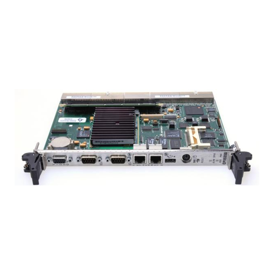
3Components on the CPV5350 Components on the CPV5350 Single Board Computer The CPV5350 Single Board Computer (SBC) carries components on both sides. Figure 3-1 shows the location of the jumpers and connectors. CR2 CR4 Figure 3-1. Location of Major Components on the CPV5350 Single Board Computer... - Page 37 Components on the CPV5350 Table 3-1 lists the connectors available to support devices on the CPV5350. Refer to Appendix A for connector pin assignments. Table 3-1. List of Front Panel Connectors, Board Connectors and Components for the CPV5350 Single Board Computer Figure 3-1 Description callout...
-
Page 38: Components For The Cpv5350 Transition Module
Components for the CPV5350 Transition Module Components for the CPV5350 Transition Module Figure 3-2 shows major components on the CPV5350 Transition Module (TM) board. http://www.motorola.com/computer/literature... -
Page 39: Figure 3-2. Location Of Major Components On The Cpv5350 Tm
Components on the CPV5350 BYPASS SMCLK SMDATA SMALT INTRUDER PBRRESET SCSI PIDE SIDE ALARM SPKR CPV5350TM 2493 9902 Figure 3-2. Location of Major Components on the CPV5350 TM Computer Group Literature Center Web Site... -
Page 40: Table 3-2. List Of Board Components For The Cpv5350 Transition Module
EIDE indicator lights, pushbutton reset, alarm indicator and speaker connector Fan tachometer connector Fan tachometer connector EIDE connector Keyboard/Mouse, power LED connector Miscellaneous Power Floppy connector USB port Ethernet 1 Keyboard/Mouse Video Connector Ethernet 2 USB port Parallel connector http://www.motorola.com/computer/literature... -
Page 41: Connecting To And Configuring Connectors
Components on the CPV5350 Connecting to and Configuring Connectors The CPV5350 provides several connectors for attaching peripheral devices. Before installing the CPV5350, you may want to connect your peripheral cables to the connectors. Refer to Appendix A for pin assignment information. Note When the identical function is available through the CPV5350’s front panel and rear transition module, you can... -
Page 42: System Memory Configurations
4Installing Options System Memory Configurations The CPV5350 has one 168-pin DIMM site for memory expansion. The DIMM sites accept industry standard PC100 compliant DIMM modules (8, 16, 32, 64, 128 or 256Mb) with or without ECC. You can use either registered or unbuffered memory modules. Installing DRAM DIMMS To install a DIMM, locate the memory bank on the single board computer. -
Page 43: Installing The Cpv5350 Dimm
Installing Options Installing the CPV5350 DIMM You do not need tools for this procedure. 1. Remove power from the chassis and disconnect all power cords. 2. Remove the CPV5350 from the chassis. 3. Locate the DIMM socket on the CPV5350. Refer to Figure 3-1. -
Page 44: Installing A Compact Flash Memory Module
3. Turn off power and remove the power lines from the system. 4. Remove the chassis or system cover(s) as necessary to access the compact PCI module. 2706 0003 Figure 4-2. Compact FLASH Placement on the CPV5350 Single Board Computer http://www.motorola.com/computer/literature... - Page 45 Installing Options Inserting or removing modules with power applied may result in damage to module components. Caution To prevent injury, use extreme caution when handling, testing, and adjusting this equipment. Dangerous voltages capable of causing death exist. Warning 5. Carefully remove the CompactPCI module from its slot and place it on a clean and protected working surface.
-
Page 46: Upgrading The Cpu
Ethernet connection at a time to determine the operating system to hardware binding for the Caution LAN controllers. Ethernet 1 settings in the BIOS always correspond to Ethernet controller 1 on the card regardless of what order the operating system reports the controllers. http://www.motorola.com/computer/literature... - Page 47 Installing Options Computer Group Literature Center Web Site...
-
Page 48: Table A-1. Pin Assignment Locator Table
APin Assignments Refer to Table A-1 to locate pin assignment information in this appendix. Table A-1. Pin Assignment Locator Table For information about pin assignments for the: Go to: - CPV5350 Single Board Computer (SBC) front Table A-2 on panel connector page A-2 - CPV5350 Transition Module (TM) rear panel connectors... -
Page 49: Pin Assignments For Cpv5350 Sbc Front Panel And Cpv5350 Tm Rear Panel Connectors
Pin Assignments for CPV5350 SBC Front Panel and CPV5350 TM Rear Panel Connectors Pin Assignments for CPV5350 SBC Front Panel and CPV5350 TM Rear Panel Connectors This section gives you pin assignment information for CPV5350 Single Board Computer (SBC) front panel connectors and CPV5350 Transition Module (TM) rear panel connectors. -
Page 50: Keyboard/Mouse Ps2 Connectors
CPV5350 Single Board Computer and CPV5350 Transition Module Signal Signal Description Number Mnemonic KBDDAT Keyboard Data AUXDAT Auxiliary Data Ground KBDVCC Keyboard Power (current limited to .75 Amp) KBDCLK Keyboard Clock AUXCLK Auxiliary Clock CGND Common Ground 2489 9902 http://www.motorola.com/computer/literature... -
Page 51: Ethernet Connectors
Pin Assignments for CPV5350 SBC Front Panel and CPV5350 TM Rear Panel Connectors Ethernet Connectors Refer to Table A-4 for pin assignments for the: CPV5350 SBC – Ethernet 1 (J13) – Ethernet 2 (J6) CPV5350 TM – Ethernet 1 (J13) –... -
Page 52: Serial Port Connector
Ground DSR- data set is ready to establish a communication link RTS- indicates to data set that UART is ready to exchange data CTS- data set is ready to exchange data modem has received a telephone ringing signal http://www.motorola.com/computer/literature... -
Page 53: Universal Serial Bus (Usb) Connectors
Pin Assignments for CPV5350 SBC Front Panel and CPV5350 TM Rear Panel Connectors Universal Serial Bus (USB) Connectors Refer to Table A-6 for pin assignments for the CPV5350 SBC, Port 1 and Port 2 (J14) Table A-6. USB Connector Pin Assignments for the CPV5350 Single Board Computer Signal Signal Description... -
Page 54: Video Connector
Video return DACVSS Video return DACVSS Video return Not connected DACVSS Video return Not connected DDCDAT Display data channel data signal for DDC2 support HSYNC Horizontal synchronization VSYNC Vertical synchronization DDCCLK Display data channel clock signal for DDC2 support http://www.motorola.com/computer/literature... -
Page 55: Parallel Connector
Pin Assignments for CPV5350 SBC Front Panel and CPV5350 TM Rear Panel Connectors Parallel Connector Refer to Table A-8 for pin assignments for the CPV5350 TM parallel port. Table A-8. Parallel Connector Pin Assignments for the CPV5350 Transition Module Signal Signal Description Number Mnemonic... - Page 56 12 pin (2 x 6) SM Bus and LM78 Table A-14 header J3, J4 4 pin (2 x 2) mate- Fan Tachometer/Power Table A-15 n-lock 12 pin (2 x 6) EIDE Indicator Lights, Table A-16 header Pushbutton Reset, Alarm Indicator, Speaker Connections http://www.motorola.com/computer/literature...
-
Page 57: Eide Headers
Pin Assignments for CPV5350 Transition Module Connectors EIDE Headers Refer to Table A-10 for EIDE header pin assignments for the CPV5350 Transition Module (TM), J5 header. Table A-10. EIDE Header Pin Assignments for the CPV5350 Transition Module Signal Signal Signal Signal Number Mnemonic... - Page 58 0, also 1, also command command register block register block select select DASP drive active ground slave present http://www.motorola.com/computer/literature A-11...
-
Page 59: Floppy Headers
Pin Assignments for CPV5350 Transition Module Connectors Floppy Headers Refer to Table A-11 for floppy header pin assignments and signal descriptions for the CPV5350 Transition Module (TM), J9 header. Table A-11. Floppy Header Pin Assignments for the CPV5350 TM Signal Signal Signal Signal Description... - Page 60 RDATA raw read data from disk drive drive common HDSEL determines the side of the floppy disk being accessed drive common DSKCHG notifies disk drive controller that the drive door is open http://www.motorola.com/computer/literature A-13...
-
Page 61: Keyboard/Mouse/Power Led Header
Pin Assignments for CPV5350 Transition Module Connectors Keyboard/Mouse/Power LED Header Refer to Table A-12 for pin assignments and signal descriptions for the Keyboard/Mouse/Power LED header (J6) on the CPV5350 Transition Module. Table A-12. Keyboard/Mouse/Power LED Header Pin Assignments for the CPV5350 Transition Module Signal Signal... -
Page 62: Usb Headers
USB headers (J12 and J19) on the CPV5350 Transition Module Table A-13. USB Header Pin Assignments for the CPV5350 Transition Module Signal Signal Description Number Mnemonic Current limited USB power DATA- USB serial communications differential pair DATA+ USB serial communications differential pair USB Port common http://www.motorola.com/computer/literature A-15... -
Page 63: Sm Bus And Lm78 Header
Pin Assignments for CPV5350 Transition Module Connectors SM Bus and LM78 Header Refer to Table A-14 for pin assignments and signal descriptions for the SM Bus and LM78 header (J1) on the CPV5350 Transition Module. Table A-14. SM Bus and LM78 Header Pin Assignments for the CPV5350 Transition Module Signal Signal... -
Page 64: Fan Tachometer Headers
Tachometer headers (J3 and J4) on the CPV5350 Transition Module. Table A-15. Fan Tachometer Header Pin Assignments for the CPV5350 Transition Module Signal Signal Description Number Mnemonic SM bus power TACH Tachometer input for fan Ground +12V 12 volt power http://www.motorola.com/computer/literature A-17... -
Page 65: Indicator Led/Miscellaneous Header
Pin Assignments for CPV5350 Transition Module Connectors Indicator LED/Miscellaneous Header Refer to Table A-16 for pin assignments and signal descriptions for the Indicator LED/Miscellaneous header (J2) on the CPV5350 Transition Module. Table A-16. Indicator LED/Miscellaneous Header Pin Assignments for the CPV5350 Transition Module Signal Signal... -
Page 66: Pin Assignments For Cpv5350 Sbc And Cpv5350 Tm Backplane Connectors
Pin Assignments Pin Assignments for CPV5350 SBC and CPV5350 TM Backplane Connectors This section gives you pinout information for: CPV5350 Single Board Computer backplane connectors (J5, J3, J4, J2, J1) CPV5350 Transition Module backplane connectors (J5, J3) http://www.motorola.com/computer/literature A-19... -
Page 67: Cpv5350 Single Board Computer, J5 Connector
Pin Assignments for CPV5350 SBC and CPV5350 TM Backplane Connectors CPV5350 Single Board Computer, J5 Connector Refer to Table A-17 for connector pin assignments and Table A-18 signal descriptions for the CPV5350 Single Board Computer (SBC), J5 connector. Table A-17. CPV5350 SBC Backplane Connector (J5) Pin Assignments Number SPKR- RESERVED... -
Page 68: Table A-18. Signal Descriptions For The Cpv5350 Single Board Computer (J5)
(-) signal of differential data pair for USB channel (USB) (0 & 1), USB levels SM Bus SMALERT SM bus interrupt signal SMBDATA System Management Bus signals SMBCLK SM bus clock signal General 5 volt power supply digital signal ground plane http://www.motorola.com/computer/literature A-21... - Page 69 Pin Assignments for CPV5350 SBC and CPV5350 TM Backplane Connectors Table A-18. Signal Descriptions for the CPV5350 Single Board Computer (J5) Backplane Connector (Continued) Signal Signal Signal Description Mnemonic EIDE (ATA- IOCS16 16 bit register is decoded DMARQ drive DMA request Secondary DMACK drive DMA acknowledge...
- Page 70 Keyboard/ MCLK clock for PS/2 mouse Mouse MDAT serial data line for PS/2 mouse Device, TTL KBDCLK clock for PC/AT or PS/2 keyboard levels KBDDAT serial data line for PC/AT or PS/2 keyboard http://www.motorola.com/computer/literature A-23...
-
Page 71: Cpv5350 Single Board Computer, J3 Connector
Pin Assignments for CPV5350 SBC and CPV5350 TM Backplane Connectors CPV5350 Single Board Computer, J3 Connector Refer to Table A-19 for connector pin assignments and Table A-20 signal descriptions for the CPV5350 Single Board Computer (SBC), J3 connector. Table A-19. CPV5350 SBC Backplane Connector (J3) Pin Assignments Number RSVD RSVD... -
Page 72: Table A-20. Signal Descriptions For The Cpv5350 Sbc (J3)
LM78 Signals FAN3, FAN2 external fan tachometer inputs INTRUDER- chassis intrusion signal BTI- board temperature interrupt signal PBYPASS power switch bypass signal SM Bus Signals SMBDATA system management bus data strobe signal SMBCLK system management bus clock signal http://www.motorola.com/computer/literature A-25... -
Page 73: Cpv5350 Single Board Computer, J4 Local Pci Connector
Pin Assignments for CPV5350 SBC and CPV5350 TM Backplane Connectors CPV5350 Single Board Computer, J4 Local PCI Connector Refer to Table A-21 for connector pin assignments for local PCI connector J4. This connector routes the local 64 bit bus to the backplane for bus expansion. -
Page 74: Cpv5350 Single Board Computer, J2 Compactpci Bus Connector
AD[45] AD[46] AD[47] AD[48] AD[49] AD[50] AD[51] AD[52] AD[53] AD[54] AD[55] AD[56] AD[57] AD[58] AD[59] AD[60] AD[61] AD[62] AD[63] PAR64 C/BE[4]# C/BE[5]# C/BE[6]# C/BE[7]# BRSVP2B4 GNT4# REQ4# GNT3# CLK4 REQ3# GNT2# SYSEN# CLK3 CLK2 REQ2# GNT1# REQ1# CLK1 http://www.motorola.com/computer/literature A-27... -
Page 75: Cpv5350 Single Board Computer, J1 Compact Pci Bus Connector
Pin Assignments for CPV5350 SBC and CPV5350 TM Backplane Connectors CPV5350 Single Board Computer, J1 Compact PCI Bus Connector Refer to Table A-23 for connector pin assignments for CPCI bus connector Table A-23. CPV5350 Backplane Connector (J1) Pin Assignments Number VCC3 ENUM# REQ64#... - Page 76 MTR1- DS1- MTR0- INDEX- DRVDENS1 GND DRVDENS0 DASP CS3- CS1- PDIAG- IOCS16- DIOR- DMACK- DIOW IORDY DMARQ INTRQ DD15 DD14 DD13 DD12 DD11 DD10 DRESET- RESET- These lines may be current limited and/or EMI filtered for direct cabling. http://www.motorola.com/computer/literature A-29...
-
Page 77: Table A-25. Signal Descriptions For The Cpv5350 Tm (J5)
Pin Assignments for CPV5350 SBC and CPV5350 TM Backplane Connectors Table A-25. Signal Descriptions for the CPV5350 TM (J5) Backplane Connector Signal Signal Signal Description Mnemonic Miscellaneous SPKR PC/AT speaker output, open collector Signals DIAG diagnostic/alarm output, open collector PBRESET pushbutton system reset input (pulled up, filtered, and debounced on host card RESET... - Page 78 SLCT select, peripheral indicates it is selected Serial COM clear to send Ports 1 and 2, data carrier detected RS-232 levels data set ready data terminal ready ring indicator request to send serial receive data serial transmit data http://www.motorola.com/computer/literature A-31...
- Page 79 Pin Assignments for CPV5350 SBC and CPV5350 TM Backplane Connectors Table A-25. Signal Descriptions for the CPV5350 TM (J5) Backplane Connector (Continued) Signal Signal Signal Description Mnemonic Floppy Disk DSKCHG- indicates drive door is open Drive, TTL DIR- controls direction of the head during step operations levels DRVDENS disk density select communication...
-
Page 80: Cpv5350 Transition Module, J3 Connector
RSVD RSVD RSVD RSVD RSVD RSVD RSVD RSVD RSVD RSVD RSVD RSVD DDCCLK DDCDAT BLUE GREEN VSYNC HSYNC LED1_2 LED3 LANB LED3 GND LANB LANB RD- LANB RD+ LED1_2 LANB TD- LANB TD+ BT1- PBYPASS FAN3 FAN2 INTRUDER- http://www.motorola.com/computer/literature A-33... -
Page 81: Table A-27. Signal Descriptions For The Cpv5350 Tm (J3) Backplane Connector
Pin Assignments for CPV5350 SBC and CPV5350 TM Backplane Connectors Table A-27. Signal Descriptions for the CPV5350 TM (J3) Backplane Connector Signal Signal Signal Description Mnemonic General 5V power ground plane Video Signal red signal Definitions GREEN green signal BLUE blue signal DACVSS video return... -
Page 82: Motorola Computer Group Documents
BRelated Documentation Motorola Computer Group Documents The Motorola publications listed in Table B-1 are referenced in this manual. You can obtain paper or electronic copies of Motorola Computer Group publications by: Visiting Motorola Computer Group’s World Wide Web literature site, http://www.motorola.com/computer/literature Contacting your local Motorola sales office Table B-1. -
Page 83: Mcg Customer Services
Wired for Management, PXE (Preboot Execution Environment), http://developer.intel.com/ial/wfm MCG Customer Services The Motorola Computer Group Customer Services organization provides numerous services that support the needs of our OEM customers throughout the qualification, development, deployment, and continued service phases of their product life cycles. Specific areas of support... - Page 84 Index airflow dimensions altitude DIMM antistatic precautions installation installing documentation battery related rating shelf life block diagram environmental specifications CPV5300 ethernet board connectors ethernet controllers installation Compact FLASH components features CPV5300 FLASH CPV5300TM form factor configurations front panel connectors connecting to headers functions connectors advanced system monitoring...
- Page 85 Index battery shock input power requirements special functions input/output interfaces specifications installing ethernet controllers speed settings installing options system memory configurations installing the CPV5300 interfaces COM1 (serial port 1) temperature COM2 (serial port 2) EIDE floppy upgrading the CPU keyboard/mouse URLs parallel port USB1 and USB2...
- Page 86 ® CPN5350 CompactPCI Single Board Computer and Transition Module Installation and Reference Guide...