Table of Contents
Advertisement
Quick Links
Advertisement
Table of Contents

Related Manuals for Dwyer Instruments UFM2


Summary of Contents for Dwyer Instruments UFM2
- Page 1 UFM2/UBT UFM2: Clamp-on Ultrasonic Flow Meter UBT: Clamp-on Ultrasonic Heat Meter User Manual UBT shown DWYER INSTRUMENTS, INC. 102 INDIANA HWY 212 Phone: 219-879-8000 MICHIGAN CITY Fax: 219-872-9057 INDIANA 46360 Web: www.dwyer-inst.com Email: info@dwyer-inst.com Issue 1.1...
-
Page 3: Table Of Contents
Connect Power and Signal Cables ..................7 2.2.1 Power Supply ......................7 2.2.2 Pulse Output Connection ..................... 8 2.2.3 Current Output (UFM2 only) ..................8 2.2.4 Modbus Connections (if fitted) ..................8 2.2.5 Temperature Sensor Probes (UBT only) ..............10 Switch On ......................... 11 2.3.1... - Page 4 Flow Alarm - Low Flow ....................29 Flow Alarm – Signal Loss ..................29 4.1.5 4-20 mA Current Output (UFM2 only, if fitted) ..............29 Modbus (if fitted) ....................... 30 5 RELOCATING THE UNIT ................. 33 6 APPENDIX ....................34 Specification ........................
-
Page 5: Introduction
This manual describes the installation and use of the UFM2 flow meter and UBT energy meter: • UFM2 is an ultrasonic clamp-on flow meter for measuring flow rate and total flow with a volume pulse output and optional Modbus or 4-20 mA flow proportional output. It can be used as a standalone meter or as part of an integral management system. -
Page 6: How Does It Work
UFM2/UBT User Manual How Does It Work? The UFM2 and UBT meters use a cross correlation transit time algorithm to provide accurate flow measurements. An ultrasonic beam of a given frequency is generated by applying a repetitive voltage pulse to the transducer crystals. -
Page 7: Package Contents
UFM2/UBT User Manual Package Contents The unit consists of two parts: Sensor Assembly Incorporating guide rails and two transducers for flow measurement. Electronics Module Consisting of the keypad and display, power, signal and Modbus connections. The Electronics Module clips onto the Sensor Assembly. -
Page 8: Display
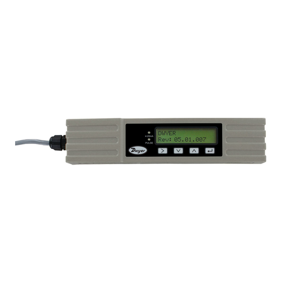
UFM2/UBT User Manual Display The meter display comprises: • One 2-line x 16 character LCD with backlight • Four tactile key switches • Two LEDs Flow Signal strength Flow Units Flow Direction Measured flow. For accurate Units applicable to * Indicates positive results, must be measured flow. -
Page 9: Quick Start Procedure
(see page 19). To use the Pulse Output features, see page 28. To use the 4-20 mA Output, see page 29 (UFM2 only). To use the Modbus interface, see page 30. The address, data rate, and configuration of the instrument must be set using the Modbus Menu (see page 22). -
Page 10: Installation
IMPORTANT: DO NOT EXPECT TO OBTAIN ACCURATE RESULTS IF THE UNIT IS POSITIONED CLOSE TO ANY OBSTRUCTION THAT DISTORTS THE UNIFORMITY OF THE FLUID FLOW PROFILE (SEE PAGE 36). DWYER INSTRUMENTS INC. ACCEPTS NO RESPONSIBILITY OR LIABILITY IF PRODUCT HAS NOT BEEN INSTALLED IN ACCORDANCE WITH THESE INSTRUCTIONS. -
Page 11: Clean The Pipe's Flow Sensor Contact Area
UFM2/UBT User Manual 2.1.2 Clean the Pipe’s Flow Sensor Contact Area Prepare the pipe by degreasing it and removing any loose material or flaking paint in order to obtain the best possible surface. A smooth contact between pipe surface and the face of the sensors is an... -
Page 12: Pulse Output Connection
NO/NC. 2.2.3 Current Output (UFM2 only, if fitted) The isolated 4-20 mA is a current source and can drive into a maximum load of 620 Ω. The 4-20 mA current output is available at the Red and Black wires. The polarities are shown in Figure 6. - Page 13 UFM2/UBT User Manual NOTE: ENSURE THE WHITE WIRES ARE CORRECTLY ASSOCIATED WITH THE BLACK & BROWN WIRES. THE BLACK/WHITE TWISTED PAIR IS FITTED WITH A BLACK SLEEVE TO DISTINGUISH BETWEEN THE BLACK/WHITE AND BROWN/WHITE PAIRS. For reliable operation of a Modbus network the cable type and installation must comply with requirements in the Modbus specification document “MODBUS over Serial Line Specification &...
-
Page 14: Temperature Sensor Probes (Ubt Only)
UFM2/UBT User Manual 2.2.5 Temperature Sensor Probes (UBT only) Two separate 4-core plug-in cables are provided for the Temperature Sensor Probes connections. These plug into the right-hand side of the Electronics Module. COLD White White White White Solder pin side... -
Page 15: Switch On
UFM2/UBT User Manual Switch On The initial screen sequence is different for the UFM2 and UBT models. 2.3.1 UFM2 Switch on the power to the Electronics Module. A start-up screen is displayed for 5 seconds followed by hardware and software version information. -
Page 16: Ubt
UFM2/UBT User Manual 2.3.2 Switch on the power to the Electronics Module. A start-up screen is displayed for 5 seconds followed by hardware and software version information. You are then prompted to enter the internal diameter of the pipe: Enter Pipe ID : 1.969 inches... -
Page 17: Adjust Flow Sensor Separation
UFM2/UBT User Manual Adjust Flow Sensor Separation Using the separation code displayed by the Electronics Module (see page 10), take the Sensor Assembly and adjust the flow sensor separation accordingly: Figure 11 Loosen the flow sensor-holding screws (left); slide to correct position (right) Undo the screws 2-3 turns, sufficiently to loosen the flow sensors and allow sideways movement. -
Page 18: Clamp Sensor Assembly To Pipe
UFM2/UBT User Manual Clamp Sensor Assembly to Pipe The next step involves clamping the Sensor Assembly onto the pipe. Ensure that you have selected a suitable location (see pages 6 and 36) and that the pipe is clean (see page 7). If you are installing the unit on a pipe with an outside diameter less than 2.36 inches (60 mm) use one or more of the... -
Page 19: Attaching To Pipe
UFM2/UBT User Manual 2.6.2 Attaching to Pipe For pipes with an outside diameter less than 2.36 inches (60 mm), attach the black clips to the bottom of the Sensor Assembly as shown below. Figure 14 Attaching pipe adaptor Place the Sensor Assembly on pipe. -
Page 20: Remove Sensor-Holding Screws
UFM2/UBT User Manual Remove Sensor-Holding Screws Release and remove the sensor-holding screws. The flow sensors are spring-loaded to ensure good contact with the pipe surface. NOTE: THE SENSOR-HOLDING SCREWS AND WASHERS SHOULD BE KEPT IN A SAFE PLACE IN CASE IT IS NECESSARY TO RELOCATE THE UNIT (SEE PAGE 28). -
Page 21: Attach The Temperature Sensors (Ubt Only)
UFM2/UBT User Manual Figure 18 Connecting the Electronics Module Attach the Temperature Sensors (UBT Only) IMPORTANT: THE TEMPERATURE SENSORS MUST BE BALANCED BEFORE INITIAL USE, USING THE PROCEDURE DESCRIBED BELOW AND USED WITH THE CABLE LENGTH SUPPLIED. EXTENDING OR SHORTENING THE CABLES WILL NEGATE THE CALIBRATION OF THE SENSORS. -
Page 22: 2.10 Normal Operation
UFM2/UBT User Manual 2.10 Normal Operation The screen sequence is different for the UFM2 and UBT models. 2.10.1 UFM2 Press The unit checks for a valid flow signal. Checking Signals Searching... If a valid signal is found, signal strength and flow rate Sig:80% are displayed. -
Page 23: Troubleshooting The Flow Reading
UFM2/UBT User Manual 2.10.3 Troubleshooting the Flow Reading The direction of flow when powered up will be taken to be the positive flow direction. The pulse output will relate to the flow in this direction. If the flow is reversed then the flow rate will still be displayed but the activity indication will change from an asterisk to an exclamation mark and no pulses will be generated. -
Page 24: Menus
The password-protected menus allow you to change the default settings: • Setup (see page 21) • Modbus (see page 22) – if Modbus output option installed • Current Output (see page 22) – UFM2 only • Pulse Output (see page 24) • Calibration (see page 25) •... -
Page 25: Setup Menu
UFM2/UBT User Manual Setup Menu If “mm” is selected for the Select Dimensions option, then the Range 0.79 – 4.33 temperatures will be displayed in 2.000 inches °C and the energy values will be in kWh. Select Dims: Inches & ... -
Page 26: Modbus Menu
UFM2/UBT User Manual Modbus Menu Invalid & Range 001 to 126 Modbus Address: Valid & Modbus Baud: 38400/19200/9600/4800/ 2400/1200 Select & Modbus Comms: 8-None-2/8-None-1/ 8-Odd-1/8-Even-1 Select & Page 22 Issue 1.1b July 20... -
Page 27: Current Output Menu (Ufm2 Only)
UFM2/UBT User Manual Current Output Menu (UFM2 only) Select 4-20mA: ON | OFF ON & Flow @ 20mA 1000.0 OFF & Valid & Flow @ 4mA 0000.0 Valid & Issue 1.1b July 20 Page 23... -
Page 28: Pulse Output Menu
UFM2/UBT User Manual Pulse Output Menu NOTE: SCREENS WITHIN THE RED BOX ARE ONLY SHOWN ON UBT MODELS. Select Pulse: Off & OFF | ON Λ Test mode press V or generate a 20ms pulse On & Pulse Type: Flow Alarm press >... -
Page 29: Calibration Menu
UFM2/UBT User Manual Calibration Menu NOTE: SET ‘ZERO CUT-OFF’ TO ZERO BEFORE SETTING ‘ZERO OFFSET’ THEN GO BACK TO SET ‘ZERO CUT-OFF’. NOTE: SCREENS WITHIN THE RED BOX ARE ONLY SHOWN ON UBT MODELS. Damping Time [s]: 10, 20, 30, 50 or 100 ... -
Page 30: Volume Totals Menu
UFM2/UBT User Manual Volume Totals Menu User Menu: Volume Total & Reset Vol. Total: NO |YES Press Page 26 Issue 1.1b July 20... -
Page 31: Diagnostics Menu
UFM2/UBT User Manual Diagnostics Menu The diagnostics menu provides some additional information about the flowmeter and its setup. The menu can be accessed by pressing the key from the main flow-reading screen. Press the keys to move between the diagnostics screens. -
Page 32: Outputs
UFM2/UBT User Manual OUTPUTS Pulse Output Pulse output can be set up to operate one of five modes: • Volumetric • Energy (UBT only) • Frequency • Low Flow Alarm • Loss of Flow (Signal) Alarm The Alarm functions allow you to set the alarm switch to Normally Open or Normally Closed. -
Page 33: Frequency Mode
The default setting is normally open, but the user can select between N/O and N/C. 4-20 mA Current Output (UFM2 only) The default 4-20 mA output setting is OFF, and the 4-20 mA LED on the keypad will not be illuminated. -
Page 34: Modbus (If Fitted)
The above faults will set the relevant status bit (see page 38). On a unit set to Imperial the temperature is in °F, Power is in BTUs and flow in US Gallons. The UFM2/UBT complies with the Modbus specification document: http://www.modbus.org/docs/Modbus_Application_Protocol_V1_1b.pdf Page 30 Issue 1.1b July 20... - Page 35 UFM2/UBT User Manual The following registers are available. Register Typical Type Meaning Notes Offset Contents Byte 0x01 Instrument Address Byte 0x03 Instrument Command Number of bytes to Byte 0x40 read 0x00 0xAC Int-16 Device ID UFM2/UBT 0xac 0x00 0x0000 OK...
- Page 36 UFM2/UBT User Manual (continued) Register Typical Type Meaning Notes Offset Contents 0x41 Units in Degrees Measured Temperature Celsius for Metric 0x88 IEEE754 (Cold) Units in Degrees float 0x00 (UBT only) Fahrenheit for Imperial 0x00 0x40 Units in Degrees Measured Temperature...
-
Page 37: Relocating The Unit
UFM2/UBT User Manual RELOCATING THE UNIT If it is necessary to relocate the unit use the following procedure: Disconnect the temperature sensors (UBT only) and MODBUS cable (if used). Unfasten hose clips and remove the complete unit from the pipe. -
Page 38: Appendix
Up to 166 pulses/sec (depending on pulse width) Frequency mode 200 Hz maximum (Range 1-200) Maximum load voltage/current 24V DC or 24V AC / 500mA Current Output UFM2 only (if fitted) 4 – 20mA Output Resolution 0.1% of full scale 620Ω... - Page 39 UFM2/UBT User Manual continued from previous page Modbus (if fitted) Format Baud rate 1200, 2400, 4800, 9600, 19200, 38400 Data-Parity-StopBits 8-None-2, 8-None-1, 8-Odd-2, 8-Even-1 Standards PI–MBUS–300 Rev. J Physical connection RS485 Temperature sensors UBT only Type PT100 Class B 4 wire Range 36 to 185°F (2 to 85°C)
-
Page 40: Default Values
Positioning For accurate measurements, the UFM2/UBT must be installed at a position where the fluid flows uniformly. Flow profile distortions can result from upstream disturbance such as bends, tees, valves, pumps and other similar obstructions. - Page 41 IMPORTANT: DO NOT EXPECT TO OBTAIN ACCURATE RESULTS IF THE UNIT IS POSITIONED CLOSE TO ANY OBSTRUCTION THAT DISTORTS THE UNIFORMITY OF THE FLOW PROFILE. DWYER INSTRUMENTS, INC. ACCEPTS NO RESPONSIBILITY OR LIABILITY IF PRODUCT HAS NOT BEEN INSTALLED IN ACCORDANCE WITH THESE INSTRUCTIONS.
-
Page 42: Error And Warning Messages
UFM2/UBT User Manual Error and Warning Messages 6.5.1 Error Messages Error Messages are displayed as a number in the diagnostics menu. Contact Dwyer Instruments if other messages appear. Status Byte Error Meaning Value Bit#7 Bit#6 Bit#5 Bit#4 Bit#3 Bit#2 Bit#1... -
Page 43: Modbus Error Messages (If Modbus Fitted)
UFM2/UBT User Manual 6.5.3 Modbus Error Messages (if Modbus fitted) Transmitter Length Test case Address Command Start Register CRC-16 (no of registers) [1 byte] [1 byte] [2 bytes] [2 bytes] [2 bytes] No error 0x01 0x03 0x00 0x00 0x00 0x20... -
Page 44: Data Entry Errors
UFM2/UBT User Manual 6.5.6 Data Entry Errors These generally advise you that the data entered is not within the specified range: Displayed when an invalid Pipe ID is entered, prompting the user Range 0.79 – 4.33 to enter a value between 0.79 and 4.33 inches depending on the 1.969 inches...
Need help?
Do you have a question about the UFM2 and is the answer not in the manual?
Questions and answers