Table of Contents
Advertisement
Available languages
Available languages
Quick Links
Advertisement
Chapters
Table of Contents

Related Manuals for Genius ZODIAC 100


Summary of Contents for Genius ZODIAC 100
- Page 1 ZODIAC 100...
- Page 2 Note per la lettura dell’istruzione Leggere completamente questo manuale di installazione prima di iniziare l’installazione del prodotto. Il simbolo evidenzia note importanti per la sicurezza delle persone e l’integrità dell’automazione. Il simbolo richiama l’attenzione su note riguardanti le caratteristiche od il funzionamento del prodotto. Notes on reading the instruction Read this installation manual to the full before you begin installing the product.
-
Page 3: Table Of Contents
Indice INDICAZIONI GENERALI DI SICUREZZA PER L’INSTALLAZIONE E LA MANUTENZIONE ....... p. 2 UTENSILI E MATERIALI ........................... p. 2 DICHIARAZIONE DI CONFORMITÀ ..................... p. 3 AVVERTENZE PER L’INSTALLATORE ....................... p. 3 1. DIMENSIONI ............................. p. 4 2. CARATTERISTICHE TECNICHE ......................p. 4 3. -
Page 4: Indicazioni Generali Di Sicurezza Per L'installazione E La Manutenzione
50mm posto a terra deve essere correttamente rilevato. AtteNZIONe! perICOlO DI sCHIACCIAmeNtO. •se il cavo di alimentazione dell’operatore ZODIAC 100 è danneggiato, esso deve essere sostituito da personale qualificato, con un cavo nuovo dello stesso tipo. Non utilizzare cavi di alimentazione differenti. -
Page 5: Avvertenze Per L'installatore
Qualsiasi altro utilizzo non punto “15”. espressamente indicato potrebbe pregiudicare l’integrità del prodotto 17) GENIUS declina ogni responsabilità ai fini della sicurezza e del buon e/o rappresentare fonte di pericolo. funzionamento dell’automazione, in caso vengano utilizzati componenti 6) GENIUS declina qualsiasi responsabilità... -
Page 6: Dimensioni
AutOmAZIONe ZODIAC 100 Le presenti istruzioni sono valide per il modello geNIus ZODIAC 2. CARATTERISTICHE TECNICHE 100. Le automazioni ZODIAC 100 consentono di automatizzare porte modello ZODIAC 100 sezionali bilanciate di garage singoli ad uso residenziale. Alimentazione (V ~ / 50 Hz.) -
Page 7: Descrizione
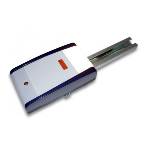
Plafoniera Sportello posteriore Lampada di cortesia Carter plastico operatore ZODIAC 100 Attacco posteriore Guida di scorrimento Carrello di trascinamento Pomello di sblocco Staffa attacco porta Gruppo di rinvio ... - Page 8 2) Fare scorrere lungo tutta la guida di scorrimento il gruppo di 6. ASSEMBLAGGIO rinvio (Fig. 7 rif. A) fino a portarlo in prossimità del terminale 6.1. Guida di scorrimento anteriore, quello opposto al gruppo innesto trazione. Nel caso si utilizzi una guida di scorrimento in due pezzi occor- 3) Assemblare l’attacco anteriore (Fig.
-
Page 9: Sblocco Esterno (Opzionale)
6.3. Sblocco esterno (opzionale) 7.1. Guida di scorrimento Qualora sia prevista l’installazione del sistema di sblocco ester- Una volta terminate le operazioni preliminari di assemblaggio, no, occorre procedere alla messa in sede del cavetto prima di si può procedere con l’installazione della guida di scorrimento iniziare l’installazione: agendo come di seguito descritto: 1) Sbloccare il carrello (vedi par. -
Page 10: Attacco Sulla Porta
8) Sollevare la guida di scorrimento fino a portare l’attacco Posizionare l’attacco sulla porta in modo che il passante posteriore al medesimo livello di quello anteriore oppure del cavetto di sblocco si trovi rivolto verso il lato sinistro della fino a raggiungere la medesima inclinazione del binario porta (rif. -
Page 11: Operatore
7.3. Operatore Una volta assemblato l’attacco posteriore con la guida di scor- rimento e terminata l’installazione della guida di scorrimento stessa, si può procedere al montaggio dell’operatore: 1) Tenendo inclinato di 15°/20° l’operatore (Fig. 20), inserire l’al- berino del motoriduttore nell’innesto presente nell’attacco posteriore della guida di scorrimento e avvicinare le alette (Fig. -
Page 12: Scheda Elettronica
8. SCHEDA ELETTRONICA 8.1. Caratteristiche tecniche 230 / 50 tensione di alimentazione (V ~ / Hz.) Alimentazione accessori (Vdc.) Carico max. accessori (mA.) -20 / +55 temperatura ambiente (°C) per modulo radiofrequenza Connettore rapido 433/868 e modulo batterie Automatica/Semiautomatica logiche di funzionamento Open/Stop/Sicurezze/ Fail Safe/ Collegamenti in morsettiera Lampeggiatore 24 Vdc. -
Page 13: Lampada Di Cortesia
Durante la manovra di chiusura, rate per l’alimentazione di rete, i segnali e gli accessori. provoca la riapertura della porta. - L’operatore ZODIAC 100 è dotato di cavo con spina bipolare per l’alimentazione 230 Vac. se viene rilevato un ostacolo in chiusura nella stessa - Per il collegamento dei comandi esterni, delle sicurezze e delle posizione per tre volte consecutive, l’automazione... -
Page 14: Programmazione
- la forza necessaria alla movimentazione della porta. 11. PROGRAMMAZIONE - i punti di rallentamento. 11.1. Impostazioni della scheda - i punti di arresto in apertura e chiusura. - il tempo pausa (in logica automatica). Effettuare le impostazioni dell’apparecchiatura tramite il dip- Switch DS1, facendo riferimento al capitolo 8.4, per ottenere il funzionamento desiderato. - Page 15 Durante questi 5 secondi è possibile, al fine di alleggerire il cari- 4 secondi (in caso contrario l’operatore effettuerà il SET UP co sul sistema di sblocco, inviare degli impulsi di OPEN entro un automatico). intervallo di 2 secondi l’uno dall’altro per fare arretrare il carrello. 1) Dare il 1°...
-
Page 16: Prelampeggio
11.3 Prelampeggio E’ possibile attivare e disattivare la funzione di prelampeggio (in seguito a un comando di OPEN, l’apparecchiatura attiva il lampeggiatore per 5 secondi prima di iniziare il movimento) agendo come di seguito descritto: 1) Premere il tasto SET UP e tenerlo premuto. 2) Dopo circa 3 secondi premere anche il tasto OPEN. -
Page 17: Memorizzazione Remota Dei Radiocomandi
3) Il led corrispondente inizia a lampeggiare lentamente per 13. MESSA IN FUNZIONE 5 sec. 4) Entro questi 5 sec. premere il pulsante desiderato sul tele- terminata l’installazione assicurarsi che nessuna parte comando 433. della porta interferisca con spazi pubblici come marciapiedi 5) Il led si accenderà... -
Page 18: Manutenzione
- Agganciare prima le due clip di fissaggio sull’innesto presente razione o d’intervento e deve rivolgersi solo ed ESCLUSIVAMENTE sulla base. a personale qualificato GENIUS o centri d’assistenza GENIUS. - Poi premere leggermente fino a sentire lo scatto di aggan- cio. -
Page 19: Guida Alla Risoluzione Dei Problemi
. GUIDA ALLA RISOLUZIONE DEI PROBLEMI Anomalia possibili cause soluzione Quando si avvia la procedura di ap- Anche durante la fase di apprendimento prendimento il LED di SET UP lampeggia le sicurezze STOP e FSW sono attive. Il loro ma l’automazione non esegue alcuna mancato od errato collegamento inibisce manovra il funzionamento dell’operatore... - Page 20 Index GENERAL SAFETY INSTRUCTIONS FOR INSTALLATION AND MAINTENANCE ........p. 2 TOOLS AND MATERIALS ........................p. 2 DECLARATION OF CONFORMITY ......................p. 3 WARNINGS FOR THE INSTALLER ......................p. 3 1. DIMENSIONS ............................. p. 4 2. TECHNICAL SPECIFICATIONS ......................p. 4 3.
- Page 21 �or �ross�hea� an� �ut�hea� s�rews •two �lat wren�hes �or 1�� �� he�a�on hea� s�rews two �lat wren�hes �or 1�� �� he�a�on hea� s�rews Material require� �or installin� the ZODIAC 100 operator an� the rele�ant a��essories (i� present): •�a�le ��0��� �� �a�le ��0��� ��...
- Page 22 19) Do not in any way �o�i�y the �o�ponents o� the auto�ate� a sour�e o� �an�er� syste�� 6) GENIUS �e�lines all lia�ility �ause� �y i�proper use or use other than �0) The installer shall supply all in�or�ation �on�ernin� �anual operation that �or whi�h the auto�ate� syste� was inten�e��...
- Page 23 AUTOMATED SYSTEM �ODIAC 100 These instru�tions apply to �o�el GENIUS �ODIAC 100� 2. TECHNICAL SPECIFICATIONS The ZODIAC 100 auto�ate� syste�s �ake it possi�le to auto�ate �alan�e� se�tional �oors o� sin�le �ara�es �or resi�ential Model �ODIAC 100 use� Power supply (V ~ � 50 Hz.) ���0...
- Page 24 Ceilin� la�p Rear �oor Courtesy li�ht Plasti� housin� �or ZODIAC 100 operator Rear �ittin� Sli�in� �ui�e Dri�e �arria�e Release kno� Door �ittin� �ra�ket Trans�ission unit...
- Page 25 �) Sli�e the trans�ission unit (Fi��� re�� A) alon� the whole sli�in� 6. ASSEMBLY �ui�e� until it is near the �ront ter�inal� the one opposite the 6.1. Sliding guide �ri�e �ouplin�� I� you use a sli�in� �ui�e in two pie�es� you �ust asse��le it� ��) Asse��le the �ront �ittin�...
- Page 26 6.3. External release (optional) 7.1. Sliding guide I� the e�ternal release syste� has to �e installe�� the �a�le When you ha�e �inishe� the preli�inary asse��ly operations� �ust �e pla�e� in its seat �e�ore �e�innin� to install� you �an �e�in installin� the sli�in� �ui�e� as �ollows: 1) Release the �arria�e (see par�...
- Page 27 8) Li�t the sli�in� �ui�e until the rear �ittin� is at the sa�e le�el Position the �ittin� on the �oor so that the throu�h�ele�ent as the �ront �ittin�� or until you rea�h the sa�e in�lination as o� the release �a�le is �a�in� towar� the le�t si�e o� the �oor the �oor’s horizontal rail�...
- Page 28 7.3. Operator When you ha�e asse��le� the rear �ittin� to the sli�in� �ui�e an� �inishe� installin� the sli�in� �ui�e� you �an install the operator: 1) While keepin� the operator in�line� at 1��/�0° (Fi�� �0)� insert the �ear�otor sha�t in the �ouplin� on the rear �ittin� o� the sli�in�...
- Page 29 8. CONTROL BOARD 8.1. Technical specifications ���0 / ��0 Supply voltage (V ~ � Hz.) �� Power supply to accessories (Vdc) �00 Accessories max. load (mA.) ��0 / +���� Operating ambient temperature (°C) �or re�ei�er �oar�s ����� / 868 Quick-fit connector an�...
- Page 30 �or powerin� the network� si�nals an� a��essories� stop. During the closing manoeuvre, it opens � The ZODIAC 100 operator has a �a�le with a two�pole plu� the door. �or ���0 Va� power supply� � To �onne�t the e�ternal �ontrols� sa�ety �e�i�es an� si�nals�...
- Page 31 � the �or�e require� to �o�e the �oor� 11. PROGRAMMING � the slow��own points� 11.1. Setting the board � the openin� an� �losin� stop points� � the pause ti�e (in auto�ati� lo�i�)� Set the applian�e with Dip�Swit�h DS1 to o�tain the operation you require�...
- Page 32 Durin� these �� se�on�s� in or�er to li�hten the loa� on the 1) Gi�e the 1st OPEN �o��an�: the operator per�or�s a release syste�� you �an sen� OPEN pulses within a ti�e inter�al �e�eleration �losin� �anoeu�re until it �ete�ts the stop o�...
- Page 33 11.3 Pre-flashing The pre��lashin� �un�tion �an �e ena�le� an� �isa�le� (�ollowin� an OPEN �o��an�� the unit a�ti�ates the �lashin� la�p �or �� se�on�s �e�ore it starts the �o�e�ent)� Pro�e�ure: 1) Press an� hol� �own the SET UP push��utton� �) Press the OPEN push��utton too a�ter a�out �� se�on�s� I� the SET UP LED �oes ON�...
- Page 34 ��) The rele�ant LED starts to �lash slowly �or �� se�� 13. START-UP �) Within these �� se�s�� press the appropriate push��utton on After installation, make sure that no part of the door the ����� re�ote �ontrol� interferes with public spaces such as pavements and�or ��) The LED li�hts up on stea�y �ea�...
- Page 35 The User �ust not in any way atte�pt to repair or to take �ire�t � Uns�rew the � s�rews in the � �orners o� the plasti� housin�� a�tion an� �ust solely �onta�t quali�ie� GENIUS personnel or � Separate it �ro� the �ase�...
- Page 36 . TROUBLESHOOTING Trouble Possible causes Solution When the learnin� pro�e�ure is starte�� The STOP an� FSW sa�ety �e�i�es are the SET UP LED �lashes �ut the auto�ate� ena�le� also �urin� the learnin� sta�e� syste� �oes not per�or� any Non��onne�tion or wron� �onne�tion �anoeu�re pre�ents the operator �ro�...
- Page 37 Index INDICATIONS GÉNÉRALES DE SÉCURITÉ POUR L’INSTALLATION ET L’ENTRETIEN ........ p. 2 OUTILS ET MATÉRIEL ..........................p. 2 DÉCLARATION DE CONFORMITÉ ......................p. 3 PRECAUTIONS POUR L’INSTALLATEUR ..................... p. 3 1. DIMENSIONS ............................. p. 4 2. CARACTÉRISTIQUES TECHNIQUES ....................p. 4 3.
- Page 38 50mm placé au sol doit être correctement détecté. ATTENTION! DANGER D’ÉCRASEMENT. •Si le câble d’alimentation de l’opérateur ZODIAC 100 est endommagé, celui-ci doit être remplacé par un câble neuf du même type, par du personnel qualifié. Ne pas utiliser des câbles d’alimentation différents.
- Page 39 Toute autre utilisation non expressément des dispositifs cités au point “1��”� indiquée pourrait compromettre l’intégrité du produit et/ou représenter 1�) GENIUS décline toute responsabilité quant à la sécurité et au bon une source de danger� fonctionnement de l’automatisme si les composants utilisés dans 6) GENIUS décline toute responsabilité...
- Page 40 à traction à courroie� Température de fonctionnement (°C) -�0 / +���� Les automatismes ZODIAC 100 ont été conçus et construits pour un usage interne et pour contrôler l’accès des véhicules. Éviter Le niveau d’émission du bruit de l’opérateur ZODIAC 1.
- Page 41 Plafonnier Capot postérieur Lampe de courtoisie Carter plastique opérateur ZODIAC 100 Patte d’attache postérieure Rail de guidage Chariot d’entraînement Poignée de déverrouillage Bride patte d’attache porte Groupe de renvoi ...
- Page 42 �) Faire coulisser le groupe de renvoi sur toute la longueur du 6. ASSEMBLAGE rail de guidage (Fig� � réf� A) pour l’amener à proximité de 6.1. Rail de guidage l’élément antérieur� opposé au groupe d’embrayage de la Si l’on utilise un rail de guidage en deux éléments� procéder à traction�...
- Page 43 6.3. Déverrouillage externe (en option) 7.1. Rail de guidage Si l’on a prévu d’installer le système de déverrouillage externe� Après avoir terminé les opérations préliminaires d’assemblage� préparer le fil avant de commencer l’installation: on peut commencer l’installation du rail de guidage comme 1) Débloquer le chariot (voir par�...
- Page 44 8) Soulever le rail de guidage de manière à amener la patte que le trou de passage du fil de déverrouillage soit tourné d’attache postérieure au même niveau que la patte d’attache vers le côté gauche de la porte (ref�_ Fig� 1�)� antérieure ou bien de manière à...
- Page 45 7.3. Opérateur Après avoir assemblé la patte d’attache postérieure au rail de guidage et terminé son installation� on peut monter l’opérateur: 1) En maintenant l’opérateur incliné de 1��°/�0° (Fig� �0)� introduire l’arbre du motoréducteur dans l’embrayage de la patte d’attache postérieure du rail de guidage et approcher les ailettes (Fig�...
- Page 46 8. PLATINE ÉLECTRONIQUE 8.1. Caractéristiques techniques �30 / ��0 Tension d’alimentation (V ~ / Hz.) �� Alimentation accessoires (Vdc.) �00 Charge maxi accessoires (mA.) -�0 / +���� Température de fonctionnement (°C) Pour platines réceptrices �33 / Connecteur rapide 868 et module batteries Automatique/Semi-automatique Logiques de fonctionnement Open/Stop/Sécurités/ Fail Safe/...
- Page 47 Durant la manœuvre de fermeture, il électrique� provoque la réouverture de la porte. - L’opérateur ZODIAC 100 est équipé d’un câble avec une fiche bipolaire pour l’alimentation �30 Vca� Si un obstacle est détecté en fermeture dans la même - Pour la connexion des commandes externes�...
- Page 48 - la force nécessaire pour l’actionnement de la porte� 11. PROGRAMMATION - les points de ralentissement� 11.1. Réglages de la platine - les points d’arrêt en ouverture et fermeture� - le temps de pause (en logique automatique)� Régler l’armoire par l’intermédiaire du Dip-Switche DS1� d’après le chapitre 8���...
- Page 49 Durant ces �� secondes� il est possible� afin d’alléger la charge sur 1) Envoyer la 1ère commande OPEN: l’opérateur effectue une le système de déverrouillage� d’envoyer des impulsions d’OPEN fermeture ralentie jusqu’à la détection de la butée� toutes les � secondes pour faire reculer le chariot� Une impulsion �) Envoyer la �e commande OPEN: l’opérateur continue avec correspond à...
- Page 50 11.3 Préclignotement Il est possible d’activer et de désactiver la fonction de préclignotement (à la suite d’une commande d’OPEN� l’armoire active la lampe clignotante pendant �� secondes avant de commencer le mouvement) en agissant comme suit: 1) Appuyer sur la touche SET UP et la maintenir enfoncée� �) Au bout de 3 secondes environ�...
- Page 51 13. MISE EN FONCTION 3) La LED correspondante commencera à clignoter lentement pendant �� s� �) Pendant ces �� s appuyer sur le bouton-poussoir souhaité de Au terme de l’opération, s’assurer qu’aucune partie de la télécommande �33� la porte n’interfère avec des espaces publics comme les ��) La LED s’allumera fixe pendant 1 seconde�...
- Page 52 - Le séparer de la base� au personnel qualifié GENIUS ou aux centres d’assistance - Loger l’unité de contrôle d’après la Fig� 36� GENIUS� - Accrocher d’abord les deux clips de fixation sur l’embrayage présent sur la base�...
- Page 53 . COMMENT RÉSOUDRE LES PROBLÈMES Anomalie Causes possibles Solution A u l a n c e m e n t d e l a p r o c é d u r e Même durant la phase d’apprentissage� les d’apprentissage� la LED de SET UP clignote sécurités ARRÊT et FSW sont actives�...
- Page 54 Inhalt ALLGEMEINE SICHERHEITSHINWEISE FÜR MONTAGE UND WARTUNG..........p. 2 WERKZEUGE UND MATERIALIEN ......................p. 2 KONFORMITÄTSERKLÄRUNG ....................... p. 3 HINWEISE FÜR DIE INSTALLATION ......................p. 3 1. ABMESSUNGEN ..........................p. 4 2. TECHNISCHE DATEN ......................... p. 4 3. ELEKTRISCHE EINRICHTUNGEN ......................p. 4 4.
-
Page 55: Allgemeine Sicherheitshinweise Für Montage Und Wartung
50 mm hoher auf dem Boden liegender Gegenstand muss ordnungsgemäß erfasst werden. ACHTUNG! QUETSCHGEFAHR •Ist das Versorgungskabel des Antriebs ZODIAC 100 beschädigt, soll es mit einem neuen Kabel der gleichen Art von Fachper- sonal ersetzt werden. Andersartige Versorgungskabel können nicht verwendet werden. -
Page 56: Konformitätserklärung
Punkt “1��” erwähnten Vorrichtungen einzusetzen� beeinträchtigen und/oder eine Gefahrenquelle darstellen� 1�) Die Firma GENIUS lehnt jede Haftung hinsichtlich der Sicherheit und des 6) Die Firma GENIUS lehnt jede Haftung für Schäden� die durch unsachgemäßen störungsfreien Betriebs der Automatik ab� soweit Komponenten auf der oder nicht bestimmungsgemäßen Gebrauch der Automatik verursacht werden�... -
Page 57: Abmessungen
AUTOMATION ZODIAC 100 Die vorliegenden Anleitungen beziehen sich auf das Modell 2. TECHNISCHE DATEN GENIUS ZODIAC 100� Die Automationen ZODIAC 100 ermöglichen die Automatisierung von Modell ZODIAC 100 a u s g e g l i c h e n e n S e k t i o n a l t o r e n Versorgungsspannung (V ~ / 50 Hz.) -
Page 58: Beschreibung
Deckenbefestigung Hintere Klappe Servicelampe Kunststoffgehäuse Antrieb ZODIAC 100 Hintere Befestigung Gleitführung Schlitten Freigabeknauf Bügel für die Befestigung am Tor Umlenkung ... -
Page 59: Montage
verformen könnten� 6. MONTAGE �) Die Umlenkung auf der ganzen Gleitführung entlang (Abb� 6.1. Gleitführung � Bez� A) bis in die Nähe des vorderen Endverschlusses Wenn eine zweiteilige Gleitführung verwendet wird� ist entgegen der Zugkupplungsgruppe schieben� 3) Die vordere Befestigung (Abb� � Bez� B) an der Umlenkung diese zuerst entsprechend den nachfolgenden Anweisungen montieren (Abb�... -
Page 60: Externe Entriegelung (Extra)
6.3. Externe Entriegelung (Extra) 7.1. Gleitführung Wenn der Einbau des e�ternen Entriegelungssystems geplant ist� Nach Beendigung der Montagearbeiten kann die Gleitführung muss der Draht vor Beginn des Einbaus eingesetzt werden: entsprechend den nachfolgend beschriebenen Schritten 1) Den Schlitten entriegeln (siehe Abschnitt ��� Punkt 3) und an eingebaut werden: das Langloch auf der Oberseite der Gleitführung fahren�... -
Page 61: Befestigung Am Tor
8) Die Gleitführung so weit anheben� dass sich die hintere Die Befestigung an der Tür so positionieren� dass die Befestigung auf derselben Höhe der vorderen Befestigung Durchgangsöffnung des Entriegelungsdrahts zur linken Seite des befindet oder dass dieselbe Neigung der waagrechten Tors hin gerichtet ist (Bez�... -
Page 62: Antrieb
7.3. Antrieb Nach der Montage der hinteren Befestigung an der Gleitführung und nach dem Einbau der Gleitführung kann der Antrieb montiert werden: 1) Den Antrieb um 1��°/�0° kippen (Abb� �0)� die Welle des Getriebemotors in die Aufnahme an der hinteren Befestigung der Gleitführung einführen und dabei darauf achten�... -
Page 63: Elektronische Karte
8. ELEKTRONISCHE KARTE 8.1. Technische Daten �30 / ��0 Versorgungsspannung (V ~ / Hz.) �� Zubehörversorgung (Vdc.) �00 Max. Last Zubehör (mA.) -�0 / +���� Temperatur am Aufstellungsort (°C) Für Empfängerkarten �33 / 868 Schnellanschluss und Batteriemodul Automatikbetrieb/ halbautomatischer Betrieb Steuerungslogiken Open/Stop/Sicherheitseinrichtun- Anschlüsse auf der Klemmenleiste... -
Page 64: Servicelampe
Stillstand. Während der Schließbewegung verwenden� wird die erneute Öffnung des Tors bewirkt. - Der Antrieb ZODIAC 100 ist mit einem Kabel mit zweipoligem Wenn ein Hindernis drei Mal hintereinander beim Schließen Stecker für die Versorgung mit �30 V Wechselstrom ausgerü- an derselben Stelle erfasst wird, erkennt die Automation diese stet�... -
Page 65: Programmierung
- notwendige Kraft für die Bewegung des Tors� 11. PROGRAMMIERUNG - Verlangsamungsstellen� 11.1. Einstellungen der Karte - Anschlagstellen beim Öffnen und beim Schließen� - Pausenzeit (bei Automatikbetrieb)� Das Gerät mit Dip-Switch DS1 mit Bezug auf Abschnitt 8�� einstellen� um die gewünschte Funktion zu erhalten� Bei schwerwiegenden Toren oder bei Bewegungsproblemen ist eine Lernphase mit einer Schubkraft von 1000N statt 600N Möchte man die Schubkraft manuell einstellen, ist der... - Page 66 Während dieser �� Sekunden besteht die Möglichkeit� im Abstand Sekunden starten (anderenfalls erfolgt das SET UP automatisch)� von jeweils � Sekunden OPEN-Impulse zu senden� um den Schlitten 1) Den ersten OPEN-Impuls senden: der Antrieb schließt bei zurückzufahren und somit die Belastung des Entriegelungssystem zu verlangsamter Geschwindigkeit�...
-
Page 67: Vorblinken
11.3 Vorblinken Es besteht die Möglichkeit� die Vorblinkfunktion (nach einem OPEN-Impuls aktiviert das Gerät das Vorblinken �� Sekunden lang bevor die Bewegung gestartet wird) laut nachfolgender Beschreibung ein- bzw� auszuschalten: 1) Die Taste SET UP anhaltend drücken� �) Nach etwa 3 Sekunden ebenfalls die Taste OPEN drücken� Wenn die LED SET UP aufleuchtet�... -
Page 68: Ferneinpeicherung Der 433-Funksteuerungen
3) Die entsprechende LED beginnt �� Sekunden lang langsam 13. INBETRIEBNAHME zu blinken� �) Innerhalb dieser �� Sekunden� die gewünschte Taste auf der Wenn die Installation abgeschlossen ist, sicherstellen, �33-Fernbedienung drücken� dass Torteile keine öffentliche Bereichen wie Gehwege und/ ��) Die LED leuchtet 1 Sekunde lang mit Dauerlicht auf� Auf diese oder Straßen behindern. -
Page 69: Wartung
- Die Kontrolleinheit wie in der Abb� 36 angegeben positionieren� Arbeiten vornehmen und hat sich ausschließlich an qualifiziertes - Die beiden Befestigungsclip auf der Kupplung auf der Basis Fachpersonal GENIUS oder an Kundendienstzentren GENIUS zu anhaken� wenden� - Dann leicht drücken� bis die Kupplungeinspannung gehört wird�... -
Page 70: Hinweise Zur Lösung Von Problemen
. HINWEISE ZUR LÖSUNG VON PROBLEMEN Störung Mögliche Ursachen Lösung Wenn das Lernverfahren gestartet wird� Die Sicherheitseinrichtungen STOP und FSW sind auch blinkt die LED SET UP � aber die Automation während des Lernverfahrens aktiv� Wenn sie gar nicht bewirkt keine Bewegung oder unsachgemäß... - Page 71 Índice INDICACIONES GENERALES DE SEGURIDAD PARA LA INSTALACIÓN Y EL MANTENIMIENTO .... p. 2 HERRAMIENTAS Y MATERIALES ......................p. 2 DECLARACIÓN DE CONFORMIDAD ....................p. 3 ADVERTENCIAS PARA EL INSTALADOR ....................p. 3 1. DIMENSIONES ........................... p. 4 2. CARACTERÍSTICAS TÉCNICAS ......................p. 4 3.
-
Page 72: Indicaciones Generales De Seguridad Para La Instalación Y El Mantenimiento
50mm de altura colocado en el suelo. ¡ATENCIÓN! PELIGRO DE APLASTAMIENTO. •Si el cable de alimentación del operador ZODIAC 100 está dañado, deberá ser sustituido por otro nuevo del mismo tipo. Esta operación ha de ser realizada por personal cualificado. No utilice cables de alimentación diferentes. -
Page 73: Advertencias Para El Instalador
Cualquier uso diverso del previsto podría perjudicar el funcionamiento del producto y/o representar 1�) GENIUS declina toda responsabilidad relativa a la seguridad y al buen fuente de peligro� funcionamiento de la automación si se utilizan componentes de la instalación que no sean de producción GENIUS�... -
Page 74: Dimensiones
Carrera útil guía de deslizamiento (mm) ���00 - 3100 - 3800 Las automaciones ZODIAC 100 han sido diseñadas y fabrica- Grado de protección Sólo para uso interno (IP�0) das para uso interno y para controlar el acceso de vehículos. -
Page 75: Descripción
Plafón Portezuela trasera Luz de cortesía Cárter de plástico operador ZODIAC 100 Empalme posterior Guía de deslizamiento Carro de arrastre Pomo de desbloqueo Brida empalme puerta Grupo de reenvío... - Page 76 �) Deslice el grupo de reenvío a lo largo de toda la guía de 6. ENSAMBLAJE deslizamiento (Fig� � ref� A) hasta colocarlo cerca del terminal 6.1. Guía de deslizamiento anterior� es decir� el opuesto al grupo de acoplamiento Si se utiliza una guía de deslizamiento dividida en dos piezas tracción�...
-
Page 77: Desbloqueo Externo (Opcional)
6.3. Desbloqueo externo (opcional) 7.1. Guía de deslizamiento Si estuviera previsto instalar el sistema de desbloqueo externo� Una vez terminadas las operaciones preliminares de ensamblaje� antes de empezar la instalación hay que proceder a colocar se puede proceder a instalar la guía de deslizamiento procediendo en su alojamiento el cable: del siguiente modo: 1) Desbloquee el carro (véase párrafo ����... -
Page 78: Empalme En La Puerta
8) Levante la guía de deslizamiento hasta que el empalme Coloque el empalme en la puerta de modo que el pasante posterior esté al mismo nivel que el empalme anterior� o del cable de desbloqueo esté dirigido hacia el lado izquierdo bien hasta alcanzar la misma inclinación del riel horizontal de la puerta (ref�... -
Page 79: Operador
7.3.Operador Una vez ensamblado el empalme posterior con la guía de deslizamiento� y finalizada la instalación de la guía de deslizamiento� se puede proceder a montar el operador: 1) Manteniendo inclinado 1��°/�0° el operador (Fig� �0)� introduzca el eje del motorreductor en el acoplamiento presente en el empalme posterior de la guía de deslizamiento y acerque las aletas (Fig�... -
Page 80: Tarjeta Electrónica
8. TARJETA ELECTRÓNICA 8.1. Características técnicas �30 / ��0 Tensión de alimentación (V ~ / Hz.) �� Alimentación accesorios (Vdc.) �00 Carga máxima accesorios (mA.) -�0 / +���� Temperatura ambiente de funcionamiento(°C) para tarjetas receptores �33 / Conector rápido 868 y módulo baterías Automática/Semiautomática Lógicas de funcionamiento Open/Stop/Disp�... -
Page 81: Luz De Cortesía
- El operador ZODIAC 100 está provisto de cable con clavija la puerta. bipolar para la alimentación �30 Vac� Si durante el cierre se detecta un obstáculo en la - Para la conexión de los mandos externos�... -
Page 82: Programación
- la fuerza necesaria para mover la puerta� 11. PROGRAMACIÓN - los puntos de deceleración� 11.1. Configuraciones de la tarjeta - los puntos de parada en apertura y cierre� - el tiempo de pausa (en lógica automática)� Configure el equipo mediante dip-Switch DS1 para obtener el funcionamiento deseado�... - Page 83 Para aligerar la carga del sistema de desbloqueo� durante estos contrario el operador realizará el SET UP automático): �� segundos se pueden enviar unos impulsos de OPEN� con un 1) Dé el 1er mando de OPEN: el operador efectúa un cierre intervalo de máximo �...
-
Page 84: Predestello
11.3 Predestello Se puede activar y desactivar la función de predestello (después de un mando de OPEN� el equipo activa el destellador durante �� segundos antes de empezar el movimiento) procediendo del siguiente modo: 1) Presione la tecla SET UP y manténgala presionada� �) Transcurridos unos 3 segundos pulse también la tecla OPEN�... -
Page 85: Memorización Remota De Los Radiomandos
13. PUESTA EN FUNCIONAMIENTO 3) El correspondiente diodo empezará a destellar lentamente durante �� seg� �) Antes de que se agoten estos �� seg� presione el pulsador deseado en el telemando �33� Finalizada la instalación, asegúrese de que ninguna ��) El diodo se encenderá con luz fija durante 1 segundo� para parte de la puerta interfiera con espacios públicos como indicar que la memorización se ha realizado correctamente�... -
Page 86: Mantenimiento
- A continuación presione ligeramente hasta oír el chasquido cualificado GENIUS o a centros de asistencia GENIUS� de enganche� - Para las conexiones remítase a las instrucciones del borde d e s e g u r i d a d y a l a F i g �... -
Page 87: Guía Para La Solución De Problemas
. GUÍA PARA LA SOLUCIÓN DE PROBLEMAS Anomalía Posibles causas Solución Cuando se empieza el procedimiento de También durante la fase de aprendizaje los dispo- aprendizaje el DIODO de SET UP destella� sitivos de seguridad STOP y FSW están activos� La falta de conexión o la conexión incorrecta de los pero la automación no realiza ninguna mismos inhibe el funcionamiento del operador... - Page 88 Inhoudsopgave ALGEMENE VEILIGHEIDSVOORSCHRIFTEN VOOR DE INSTALLATIE EN HET ONDERHOUD ....p. 2 GEREEDSCHAPPEN EN MATERIALEN ....................p. 2 VERKLARING VAN OVEREENSTEMMING ................... p. 3 WAARSCHUWINGEN VOOR DE INSTALLATEUR ................... p. 3 1. AFMETINGEN ............................ p. 4 2. TECHNISCHE EIGENSCHAPPEN ....................... p. 4 3.
-
Page 89: Algemene Veiligheidsvoorschriften Voor De Installatie En Het Onderhoud
50 mm moet op correcte wijze worden gedetecteerd. LET OP! BEKNELLINGSGEVAAR. •Als de voedingskabel van de aandrijving ZODIAC 100 beschadigd is, moet hij door gekwalificeerd personeel worden ver- vangen met een nieuwe kabel van hetzelfde type. Gebruik geen andere voedingskabels. -
Page 90: Waarschuwingen Voor De Installateur
��) Houd radio-afstandsbedieningen of alle andere impulsgevers buiten het bereik 9) GENIUS is niet aansprakelijk als de regels der goede techniek niet in acht van kinderen, om te voorkomen dat het automatische systeem onopzettelijk genomen zijn bij de bouw van het sluitwerk dat gemotoriseerd moet worden, kan worden aangedreven�... -
Page 91: Afmetingen
AUTOMATISCH SYSTEEM ZODIAC 100 Deze instructies gelden voor het model GENIUS ZODIAC 100� 2. TECHNISCHE EIGENSCHAPPEN Met de automatische systemen ZODIAC 100 kunnen sectionale garagedeuren met contragewicht voor woningen worden Model ZODIAC 100 geautomatiseerd� Voeding (V ~ / 50 Hz.) �30... -
Page 92: Beschrijving
4. BESCHRIJVING Plafonnière Klepje achterkant Lampje verlichting Kunststof behuizing aandrijving ZODIAC 100 Bevestiging achterkant Geleiderail Geleideslede Ontgrendelingsknop Bevestigingsbeugel deur Transmissiegroep ... -
Page 93: Assemblage
�) Schuif de transmissie-eenheid over heel de geleiderail (Fig� 6. ASSEMBLAGE � ref� A) tot vlakbij het uiteinde aan de voorkant, de kant 6.1. Geleiderail tegenover de aandrijfkoppelingsgroep� Als een geleiderail in twee delen wordt gebruikt, moet hij 3) Assembleer de bevestiging aan de voorkant (Fig� � ref� B) met de transmissie-eenheid (Fig�... -
Page 94: Externe Ontgrendeling (Optioneel)
6.3. Externe ontgrendeling (optioneel) 7.1. Geleiderail Als de installatie met een e�terne ontgrendeling is uitgerust, Als alle assemblagehandelingen vooraf zijn verricht, kan met moet het kabeltje op zijn plaats worden gezet alvorens met het het installeren van de geleiderail worden begonnen door te installeren te beginnen: handelen zoals hieronder beschreven: 1) Ontgrendel de geleideslede (zie par�... -
Page 95: Bevestiging Op De Deur
8) Licht de rail op tot de achterste bevestiging op dezelfde Zet de bevestiging zo op de deur dat het gat voor het ontgrendelingskabeltje naar de linkerkant van de deur is hoogte is als de voorste, of tot de geleiderail dezelfde hoek gericht (ref�_... -
Page 96: Aandrijving
7.3. Aandrijving Zodra de bevestiging aan de achterkant met de rail is geassembleerd en de geleiderail zelf is geïnstalleerd, kan de aandrijving worden gemonteerd: 1) Steek, terwijl de aandrijving met een hoek van 1��°/�0° wordt gehouden (Fig� �0), het asje van de motorreductor in de verbinding aan de achterkant van de geleiderail, en duw de pootjes (Fig�... -
Page 97: Elektronische Kaart
8. ELEKTRONISCHE KAART 8.1. Technische eigenschappen �30 / ��0 Voedingsspanning (V ~ / Hz.) �� Voeding accessoires (Vdc.) �00 Max. belasting accessoires (mA.) -�0 / +���� Omgevingstemperatuur (°C) voor ontvangerkaarten �33 / Snelconnector 868 en batterijenmodule Automatisch / Halfautomatisch Bedrijfslogica’s Open/ Stop / Veiligheidsvoorzieningen Aansluitingen op klemmenbord / Fail safe / Signaallamp ��... -
Page 98: Verlichting
Als tijdens het sluiten drie keer achter elkaar een obstakel op - De aandrijving ZODIAC 100 heeft een kabel met tweepolige dezelfde plaats wordt gedetecteerd, beschouwt het stekker voor een voeding van �30 Vac�... -
Page 99: Programmering
- de kracht die nodig is om de deur te bewegen� 11. PROGRAMMERING - de vertragingspunten� 11.1. Instellingen van de kaart - het punt waarop moet worden gestopt bij het openen en sluiten� - de pauzetijd (bij automatische logica)� Stel de apparatuur in met behulp van de dipschakelaar DS1, met verwijzing naar hoofdstuk 8��, voor de gewenste werking�... - Page 100 Tijdens deze �� seconden kunnen, om de belasting van het (als dat niet gebeurt voert de aandrijving een automatische ontgrendelingssysteem te verlichten, de OPEN-impulsen achter SET-UP uit)� elkaar worden verzonden met een interval van � seconden, 1) Geef het 1e OPEN-commando: de aandrijving sluit de deur teneinde de geleideslede achteruit te laten gaan�...
-
Page 101: Voorknipperfunctie
11.3 Voorknipperfunctie De voorknipperfunctie (na een OPEN-commando activeert de apparatuur de signaallamp �� seconden alvorens de beweging te starten) kan worden geactiveerd en gedeactiveerd door als volgt te handelen: 1) Druk de SET-UP-toets in en houd hem ingedrukt� �) Druk na ongeveer 3 seconden ook de OPEN-toets in� Als de SET-UP-led gaat branden is de voorknipperfunctie geactiveerd, als hij echter gedoofd blijft is de functie gedeactiveerd�... -
Page 102: Op Afstand 433-Afstandsbedieningen In Het Geheugen Opslaan
3) De bijbehorende led begint langzaam te knipperen 13. INBEDRIJFSTELLING gedurende �� sec� �) Druk binnen deze �� sec� op de gewenste knop op de Controleer, nadat de installatie is beëindigd, of de deur �33-afstandsbediening� nergens in openbare ruimten komt zoals de stoep en/of de ��) De led blijft 1 seconde lang branden, waarmee wordt straat. -
Page 103: Onderhoud
- Plaats de bedieningseenheid erin zoals aangegeven in Fig� 36� raties of andere directe ingrepen, en dient zich uitsluitend te - Haak eerst de twee bevestigingsclips aan de aansluiting op wenden tot gekwalificeerd en geautoriseerd GENIUS-personeel de basis� of een erkend GENIUS-servicecentrum�... -
Page 104: Gids Voor Het Oplossen Van Problemen
. GIDS VOOR HET OPLOSSEN VAN PROBLEMEN Storing Mogelijke oorzaken Oplossing Bij het starten van de zelflerende procedure Ook tijdens de zelflerende fase zijn de knippert de SET-UP-led, maar het veiligheidsinrichtingen STOP en FSW actief� Als automatische systeem voert geen enke- ze niet of verkeerd zijn aangesloten wordt de le beweging uit werking van de aandrijving verhinderd... - Page 105 note - notes - note - notas - anmerkung - opmerkingen...
- Page 106 note - notes - note - notas - anmerkung - opmerkingen...
- Page 108 Les descriptions et les illustrations du présent manuel sont fournies à titre indicatif. GENIUS se réserve le droit d’apporter à tout moment les modifications qu’elle jugera utiles sur ce produit tout en conservant les caractéristiques essentielles, sans devoir pour autant mettre à...
- Page 109 ZODIAC 100...
- Page 110 Note per la lettura dell’istruzione Leggere completamente questo manuale di installazione prima di iniziare l’installazione del prodotto. Il simbolo evidenzia note importanti per la sicurezza delle persone e l’integrità dell’automazione. Il simbolo richiama l’attenzione su note riguardanti le caratteristiche od il funzionamento del prodotto. Notes on reading the instruction Read this installation manual to the full before you begin installing the product.
- Page 111 - Non eseguire alcuna modifica sui componenti facenti parte il sistema di automazione. - Astenersi da qualsiasi tentativo di riparazione o d’intervento diretto e rivolgersi solo a personale qualificato GENIUS. - Far verificare almeno semestralmente l’efficienza dell’automazione, dei dispositivi di sicurezza da personale qualificato.
- Page 113 � At least e�ery si� �onths: arran�e a �he�k �y quali�ie� personnel o� the auto�ate� syste� an� the sa�ety �e�i�es� DESCRIPTION The ZODIAC 100 auto�ate� syste� is i�eal to auto�ate �alan�e� se�tional �oors o� sin�le �ara�es �or resi�ential use� The auto�ate� syste�s �onsist o� an ele�tro��e�hani�al operator� ele�troni� �ontrol unit an� �ourtesy li�ht �uilt into a sin�le unit�...
- Page 115 - N’effectuer aucune modification sur les composants qui font partie du système d’automation� - Éviter toute tentative de réparation ou d’intervention directe et s’adresser uniquement à du personnel qualifié GENIUS� - Faire vérifier� au moins tous les six mois� l’efficience de l’automatisme� des dispositifs de sécurité par du personnel qualifié�...
- Page 117 Abb.2 HANDBETRIEB Der Antrieb ZODIAC 100 ist mit einem System für die Notentrieglung von innen ausgerüstet� Auf Anfrage kann ein Schloss angebracht werden� durch das die Betätigung der Entriegelung auch von außen möglich ist� Sollte es aufgrund von Stromausfall oder Betriebsstörungen der Automation erforderlich sein� das Tor mit der Hand zu betätigen�...
- Page 119 Lea detenidamente las instrucciones antes de utilizar el producto y consérvelas para posibles usos futuros. NORMAS GENERALES DE SEGURIDAD La automación ZODIAC 100� si se instala y utiliza correctamente� garantiza un elevado grado de seguri- dad� Algunas simples normas de comportamiento pueden evitar inconvenientes o accidentes: - No se detenga absolutamente debajo de la puerta�...
- Page 121 Lees de instructies aandachtig door alvorens het product te gebruiken, en bewaar ze voor eventuele toekomstige raadpleging. ALGEMENE VEILIGHEIDSVOORSCHRIFTEN Het automatische systeem ZODIAC 100 garandeert, als het op correcte wijze is geïnstalleerd en gebruikt, een hoge mate van veiligheid� Daarnaast kunnen een aantal simpele gedragsregels accidentele ongemakken voorkomen: - Blijf nooit onder de deur staan�...
- Page 124 Les descriptions et les illustrations du présent manuel sont fournies à titre indicatif. GENIUS se réserve le droit d’apporter à tout moment les modifications qu’elle jugera utiles sur ce produit tout en conservant les caractéristiques essentielles, sans devoir pour autant mettre à...
Need help?
Do you have a question about the ZODIAC 100 and is the answer not in the manual?
Questions and answers