
Related Manuals for protech EVO COMPACT

Summary of Contents for protech EVO COMPACT
- Page 1 EVO TRACKED MACHINES Protech Machinery Ltd WOOLRIDGE FARM HARTPURY GLOUCESTERSHIRE GL19 3BG...
- Page 2 BS EN 4413 : 2010 Hydraulic fluid power - General rules & safety requirements for systems & their components BS 5401: 1990 Guide to information content and presentation of operator’s manuals provided for tractors and machinery for agriculture and forestry. Signed On behalf of Protech Machinery Date…Tuesday, 06 October 2020 Page | 2...
-
Page 3: Table Of Contents
LIST OF CONTENTS ______________________________________________________________________ LIST OF CONTENTS ........................3 INTRODUCTION ..........................4 PRODUCT SPECIFICATION ......................5 DIMENSIONS - TRANSPORT ......................6 PARTS REFERENCE ........................7 SAFETY STATEMENT ......................... 10 INTERPRETATION AND UNDERSTANDING THIS MANUAL ..........11 SAFETY INFORMATION ......................12 PERSONAL PROTECTIVE EQUIPMENT ................... -
Page 4: Introduction
Whereas every effort has been made to ensure the Post Driver conforms to Protech policy of quality, the machine cannot be expected to withstand abuse caused by misuse and negligence by the operator. -
Page 5: Product Specification
PRODUCT SPECIFICATION Each machine will have a degree of customization. Final definition on each sales order. EVO1S Standard configuration EVO COMPACT Standard configuration ✓ 1.6mtr wide track base ✓ 1.52mtr wide track base ✓ 400 mm wide tracks ✓ 320mm wide tracks ✓... -
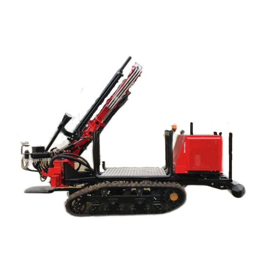
Page 6: Dimensions - Transport
DIMENSIONS - TRANSPORT EVO1S is fitted with a mast rest bracket on which the mast should be laying when transporting the machine. A “stay bar” is also provided to protect the tilt cylinder. This can be set in position with 2 linch pins. This is to avoid mast hydraulic cylinders to receive road vibrations and will extend life of cylinders. -
Page 7: Parts Reference
PARTS REFERENCE Page | 7... - Page 8 Page | 8...
- Page 9 Page | 9...
-
Page 10: Safety Statement
SAFETY STATEMENT ___________________________________________________________________ Protech Machinery Ltd are concerned for your safety and that of others around you when operating this machinery and its associated equipment. This safety statement is our primary way of notifying you and bringing to your attention the potential hazards associated with the EVO Series track machines and its equipment. -
Page 11: Interpretation And Understanding This Manual
Although every effort has been made to warn you of the dangers there is no substitute for good common sense and safe practices. We at Protech Machinery Ltd want you to get the most from your machine in a safe and responsible manner at all times. -
Page 12: Safety Information
SAFETY INFORMATION ___________________________________________________________________ This machine has the potential to be extremely dangerous - in the wrong hands it can maim, cause serious injury or even kill. It is therefore imperative that both the owner and operator of the machine reads and understands the following section to ensure they are fully aware of the dangers that do, or may exist, and their responsibilities surrounding the use and operation of the machine. - Page 13 • Never leave a running machine unattended. Always switch the engine off and remove the ignition key • Always stop and switch off the machine if persons or animals enter the work area. Do not restart the machine until they are at a safe distance. •...
- Page 14 POTENTIAL SIGNIFICANT DANGERS ASSOCIATED WITH THE USE OF THIS MACHINE: Injuring of feet. No person must be in this area when the Post Driver is raised or lowered by the tractor or near to the rear leg and foot plate when operating this control. Crushing under the falling weight.
-
Page 15: Personal Protective Equipment
PERSONAL PROTECTIVE EQUIPMENT ___________________________________________________________________ It is advised that the following personal protective safety equipment be worn at all times when operating this machinery. EC Personal Protective Equipment Directive (89/686/EEC). • Eye wear to a minimum of high energy low impact protection. •... -
Page 16: Emergency Stops / Safety Devices
EMERGENCY STOPS / SAFETY DEVICES ___________________________________________________________________ Each machine produced has an emergency stop buttons fitted to it. The emergency stop when actuated will stop the engine immediately. Caution must be taken as some hydraulic movement is still possible due to the effects of gravity and stored energy, machine mechanism weights and fluid return when control levers are moved. -
Page 17: Hazards And Safe Use Of The Machine And Equipment
These machines are heavy, some are almost 5 tons and can travel at 30KPH with a high center of gravity. Please take extra care when using them. We at Protech Machinery want you to get the most out of your machine, but in a safe and responsible manner. -
Page 18: Machine Operation
Ensure the operator is protected from flying debris. Safety glasses should be worn. Always check for worn hydraulic components. Always ensure the rope is not damaged. Replacements must be a certified Protech rope. When working on sloping ground, it is far safer to drive up and down rather than across the slope. -
Page 19: Machine Safety Decals
MACHINE SAFETY DECALS Standard Triangle indicate Alert/Warning Warning read Product Manual Warning danger area from tilting mast Warning danger feet being crushed. Warning eye protection must be warn Warning ear protection must be warn Warning Danger of falling weight Warning Danger of overhead cables Lubrication Point Warning danger of fingers and hands being crushed... -
Page 20: Control Functions Of The Post Driver
CONTROL FUNCTIONS OF THE POST DRIVER ______________________________________________________________________ The photo below displays the layout of the control panel. Moving the control lever up or down operates the function in the direction displayed of the Post Driver. SLEW ARM ______________________________________________________________________ Operating the slew control lever pivots the slew arm from parallel to the main frame through 120 degrees. -
Page 21: Telescopic Arm
TELESCOPIC ARM ______________________________________________________________________ Operating the Telescopic control lever extends and retracts the inner slew arm through 800mm. TRAPPING ZONE CRUSHING ZONE As the control is mounted to the inner slew arm, it will move as the telescopic control. The operator must work in the control area of the post driver to avoid all trapping zones. REAR LEG ______________________________________________________________________ Operating the Rear Leg control lever extends and retracts the leg and foot plate which is... -
Page 22: Mast Forward Tilt
MAST FORWARD TILT ______________________________________________________________________ Operating the Mast Forward Tilt control lever pitches the mast forward and back (23 degrees forward and back from mast vertical position). This maintains a vertical mast while on undulating ground. Check clearance prior tilting your mast Page | 22... -
Page 23: Mast Side-Tilt
MAST SIDE-TILT ______________________________________________________________________ Operating the Mast Side Tilt control lever pitches the mast side to side (35 degrees each side from mast vertical position). This maintains a vertical mast while on undulating ground. Check clearance prior tilting your mast. Keep people away from this trapping zone during this operation. Page | 23... -
Page 24: Driver Weight Control
DRIVER WEIGHT CONTROL ______________________________________________________________________ Operating the Driver Weight control will immediately raise and lower the weight. Everyone must be kept clear from this crushing zone during operation of this control. CRUSHING ZONE TRAPPING ZONE TRACK EXTENSION ______________________________________________________________________ Operating this control extends the left side track to give the machine a wider footprint. Your extension is approximately 500 mm. -
Page 25: Telemast Control
TELEMAST CONTROL ______________________________________________________________________ This controls the telescopic mast Left Track Control This controls the left side hydraulic motor. Moving the lever forward will move the track in the forward direction, and moving the lever backwards will move the track in the reverse direction Right Track Control This controls the right side hydraulic motor. -
Page 26: Rock Spike Control
ROCK SPIKE CONTROL ______________________________________________________________________ TRAPPING POINT CRUSHING ZONE Before using the rock spike the weight will have to be raised so that the rock spike can be moved into position. The rock spike is located on a support pin when not in use. Raise the rock spike using the control lever to give clearance, then manually swing into position. -
Page 27: Auger Drive
AUGER DRIVE ______________________________________________________________________ Connect the Auger head / hydraulic pipes Beware to connect your pressure and drain pipe to the right couplings. clock/reverse PRESSURE (Female coupling) DRAIN (Male coupling) 1. Put machine in `park` position. 2. Lower rear leg for stability. 3. - Page 28 6. Use the `Right Track` lever to rotate the drill and `Rock Spike` lever to lower the drill 7. On completion, `right track` forward and `rock spike` up. 8. Lift the weight up clear of the auger. 9. Use the `rock spike` lever to swing the auger clear of the mast 10.
-
Page 29: Auto-Level
AUTO-LEVEL ______________________________________________________________________ Auto-level operating Your machine has been fitted with Protech auto-level system. This is a single button hit to level your mast. 2-Axis Auto Levelling system One-push button to align your post-driver mast to the vertical position. One of contractors’ favourites, as it is a Substantial time saver for intensive fencing. -
Page 30: Auto-Level Setup
Auto-level setup You should not have to go to setup as the fixture has been calibrated at factory. After intensive usage or due to power shortage, you may have to re-calibrate. In such case, follow the instructions below : By pressing the arrows then enter buttons, the calibration and settings windows can be accessed. -
Page 31: Remote Control
REMOTE CONTROL ______________________________________________________________________ Overview. Your machine has been fitted with remote control system. The Evo track machine has been developed to operate with a Scanreco radio control unit. Please read carefully and understand the operation. Failure to read and fully understand this information could result in injury or death. - Page 32 10. Emergency stop switch (will only stop Scanreco system). 11. Remote on button. Before operation of the radio control system. Please be advised that when the radio control transmitter is switched on and paired to the receiver it will override the park brake and high speed tracking switch functions. The throttle and tracking will operate on both independently.
- Page 33 Electrical Schematic Page | 33...
-
Page 34: Welder
WELDER ______________________________________________________________________ Your machine has been fitted with welder capability for steel posts operations. The welder power pack is built into the, with connections and on/off switch located on the side of the machine. The welding output is totally isolated from the machine electrical circuit. -
Page 35: Initial Checks Before Operation
INITIAL CHECKS BEFORE OPERATION ___________________________________________________________________ Before operation, please check and inspect the following: • Engine oil level • Coolant level • Fuel level • Hydraulic oil level • Park brake operation • Safety devices are working correctly • Transportation devices have been removed and locking pins reinserted •... -
Page 36: Operating The Drive Motors And Moving The Machine
OPERATING THE DRIVE MOTORS AND MOVING THE MACHINE ________________________________________________________________ Failure to observe the following could result in Serious Injury or Death After the initial checks have been carried out we can start with moving the machine. If moving the machine over long distances it is advised that the transportation bars be fitted and the mast lowered into the stowed position. -
Page 37: Using The Post Driving Equipment
USING THE POST DRIVING EQUIPMENT ________________________________________________________________ Failure to observe the following could result in Serious Injury or Death When the machine is in position, apply the park and remove any transportation bars that may be fitted ready for operation. After checking your surroundings for any hazards and observing the relevant labeled lever, move it in the required direction of travel. -
Page 38: Electrical Functions
ELECTRICAL FUNCTIONS Switches and Controls From left to right the switches are:- lights, fast, throttle control, engine control, e-stop and park. Lights. This switch turns on/off the work lights as required, and is internally illuminated when operated. Fast. This will operate the fast solenoid and switch the hydraulic motors to fast speed. The switch is internally illuminated when fast speed is selected. -
Page 39: Junction Box
Junction box. Emergency stop Diverter Lights Park brake Fast speed Throttle + Throttle - Page | 39... -
Page 40: Cuircuit Diagrams
Cuircuit Diagrams. Machine diagram Page | 40... - Page 41 Page | 41...
-
Page 42: Engine Diagram
Engine diagram Page | 42... -
Page 43: Engine Control Box
Engine control box. Normal operation “0” : standby “I” : LED on top energise battery “II” : pre-heating is on “III” : engine kick-starts, release to position “I” Engine monitoring / issues In the event of an engine shutdown, the fuel solenoid de-energises and the engine stops. The appropriate LED displays. -
Page 44: Maintenance
MAINTENANCE ______________________________________________________________________ Daily Check the lift rope for any signs of wear. If in doubt, change the rope. Check hydraulic hoses for any signs of wear. If in doubt change the hose. Grease the mast where the driver weight runs. Check all nuts and bolts are tight. -
Page 45: Track Tension
Monthly maintenance Check engine oil level, top up as necessary. Check hydraulic oil level, top up as necessary. Check engine coolant level, top up as necessary. Check tightness of wear pads. Tighten as necessary. BEWARE: On EVO2 and Coolant Oil level needs EVO3, your machine will be level needs checking on a monthly... -
Page 46: Recommanded Lubricants
RECOMMANDED LUBRICANTS Mechanical parts / greasing points: we recommend multipurpose grease - generously Hydraulic system oil: we recommend using : 10µm oil filter PROTECH ref. HVSZ0008 HV46 - High viscosity oil Change filter every 500 hours or 1 year maximum On a warm engine, if your indicator goes in yellow, change filter rapidly. -
Page 47: Trouble Shooting
TROUBLE SHOOTING Symptom Possible cause Solution Track damage Excessive tread wear. Replace track Loosening/breaking of internal structure. Track slackens Faulty tensioner valve. Replace valve frequently Worn tensioner components Replace worn components Upper track does not Upper track rollers worn Replace track rollers stay in position Lower track does not Lower track rollers worn... -
Page 48: Checklist
CHECKLIST Who can carry out the plant / equipment documented inspection? All plant / equipment must be inspected and signed off by a competent person. A competent person is: • A person that has been trained to use the plant / equipment being inspected or •... - Page 49 PROTECH MACHINERY LTD Woolridge Farm, Gloucester Road, Hartpury, Gloucester GL19 3BG Tel: 01452 700 713 Email: sales@protechmachinery.com Company reg. no. 4958012 VAT no. 834 1361 48 Page | 49...
Need help?
Do you have a question about the EVO COMPACT and is the answer not in the manual?
Questions and answers