Table of Contents
Advertisement
Advertisement
Table of Contents

Related Manuals for Tesla Gen 3


Summary of Contents for Tesla Gen 3
- Page 1 Gen 3 Wall Connector Manual Type 2 Handle, Three Phase...
-
Page 2: Table Of Contents
Important Safety Information......2 Product Specifications.........4 Wall Connector Label........... 5 Power Supply Options......... 6 Circuit Breaker Rating / Maximum Output................... 9 Using Wall Connector.......... 11 Features..............12 Connectivity................12 Hosted Access Point............12 Local Network................ 12 Residual Current Device (RCD)........13 Ground Monitor Interrupter.......... -
Page 3: Important Safety Information
Read all instructions before using this product. Save these instructions. Wall Connector features built-in RCD Type A + DC 6mA. This manual contains important instructions for the Tesla Gen 3 Wall Connector that shall be followed during installation, operation, and maintenance. Please review all warnings and cautions before installing and using the Wall Connector. - Page 4 50˚ C (-22˚ F to 122˚ F). CAUTION: Wall Connector should only be installed by personnel who are trained and qualified to work on electrical systems. CAUTION: Ensure that Wall Connector is within storage temperature when moving, transporting, or storing. Gen 3 Wall Connector Manual...
-
Page 5: Product Specifications
-40˚C to 85˚C (-40˚F to 185˚F) Enclosure Rating IP 55 Ventilation Not required Means of Disconnect External branch circuit breaker Residual Current Detection Integrated (Type A + DC 6 mA) Wi-Fi 2.4 GHz, 802.11b/g/n Certifications CE, IEC 61851-1 CB Gen 3 Wall Connector Manual... -
Page 6: Wall Connector Label
• TSN: Tesla Serial Number • Input: Max input power • Output: Max output power • MAC: Unique MAC address assigned to the Wall Connector • SSID: Unique Wi-Fi access point assigned to the Wall Connector Gen 3 Wall Connector Manual... -
Page 7: Power Supply Options
CAUTION: Double check N connection is 230 V L to N at terminals of wirebox before energizing. NOTE: Blue is used as the IEC standard for neutral. Some markets may use other colors to symbolize neutral and line conductors. Gen 3 Wall Connector Manual... - Page 8 NOTE: For 230V Line to Line connections, without a Neutral, connect one Line from the grid to the Neutral terminal of the wirebox CAUTION: Double check N connection is 230 V L to N at terminals of wirebox before energizing. Gen 3 Wall Connector Manual...
- Page 9 230 V L to N at terminals of wirebox before energizing. *When connecting to a 230 V delta no neutral grid, land one of the line connections in the neutral terminal of the wirebox. Gen 3 Wall Connector Manual...
-
Page 10: Circuit Breaker Rating / Maximum Output
Any amperage between 6 A and 32 A can be selected. Estimate power output for various grid connections below: NOTE: Some Tesla vehicles may draw less current than the max output of Wall Connector. Actual charging rate depends on Wall Connector output and onboard charger in the vehicle. See Tesla website for vehicle specifications. - Page 11 BS 7671. It is the responsibility of the installer to ensure that the requirements of BS7671 are met - please refer to Tesla's application note online that discusses this topic in more detail. NOTE: The use of an dedicated earth rod for the EVSE will not generally be a practical solution to meet the...
-
Page 12: Using Wall Connector
NOTE: The vehicle must be unlocked for the charge handle to be removable. 5. Remove the charge handle from the vehicle charge port. 6. Wrap the charge cable counter-clockwise around the Wall Connector and insert the charge handle into the holster. Gen 3 Wall Connector Manual... -
Page 13: Features
Connectivity Wall Connector is equipped with Wi-Fi to communicate with local site routers, vehicles, mobile devices, other Wall Connectors, and other Tesla products. Hosted Access Point Wall Connector hosts a WPA2 password-secured, 2.4 GHz, 802.11 Wi-Fi access point network to facilitate commissioning and connecting to other devices. -
Page 14: Residual Current Device (Rcd)
Residual Current Device (RCD) Wall Connector features built-in RCD Type A + DC 6mA. The benefit of this protection is that RCD Type B are not required when installing Gen 3 Wall Connectors, consult local regulations on the type of breaker required. -
Page 15: Power Outages
50˚C (122˚F). In rare circumstances, Wall Connector may begin reducing amperage at 35˚C (95˚F) ambient temperatures. Adjustments to amperage are automatic and do not require user input; Wall Connector will return to starting current when temperatures are reduced. Gen 3 Wall Connector Manual... -
Page 16: Wall Connector External Components
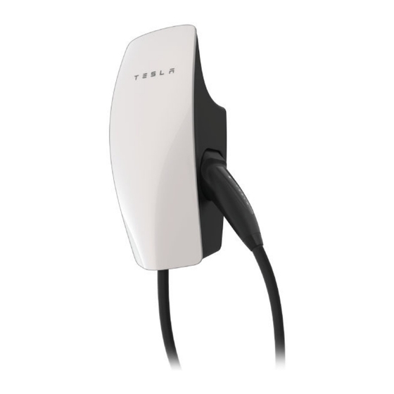
WALL CONNECTOR EXTERNAL COMPONENTS "Wall Connector" refers to the product as a whole. 1. Faceplate 2. Light bar (vertical) 3. Main unit 4. Charge handle button 5. Charge handle Gen 3 Wall Connector Manual... -
Page 17: Wall Connector Internal Components
1. Contact blades 2. Temperature sensor 3. Conductor terminals 4. Zip tie anchor 5. Sliding contacts 6. Wirebox drainage opening (enables protection) 7. Neutral 8. Line 1 9. Line 2 10. Line 3 11. Earth Gen 3 Wall Connector Manual... -
Page 18: In The Box
NOTE: The hex bit, zip tie, and fasteners are located in a plastic bag inside the wirebox, which comes attached to the main unit of the Wall Connector. NOTE: Wall plugs are not included. If installing in concrete or other like materials, use 6 mm wall plugs. Gen 3 Wall Connector Manual... -
Page 19: Tools
Wire Stripper (If installing on wood (If installing on wood walls) walls) Level Smartphone (with Wi-Fi) Power Drill Optional Tools Step Bit, 29 mm (1-1/8 in) Step Bit, 35 mm (1-3/8 in) Computer (with Wi-Fi) Gen 3 Wall Connector Manual... -
Page 20: Installation Considerations
Install Wall Connector in a location with ample clearance on all sides to allow the charge cable to loop around the unit and the charge handle to comfortably land in the side dock. NOTE: If constrained by space, a cable organizer can be installed near the Wall Connector. Gen 3 Wall Connector Manual... - Page 21 Wi-Fi signal reception. NOTE: If a mobile device is able to connect to local Wi-Fi at a given location, it is a good indication that Wall Connector will also be able to connect. Gen 3 Wall Connector Manual...
- Page 22 Wall Connector's wirebox has multiple wire entry options. Choose one entry path and follow installation instructions based on chosen entry path. 1. Top entry location 2. Rear entry locations (left or right) 3. Bottom entry location Gen 3 Wall Connector Manual...
-
Page 23: Installation Steps
NOTE: It is the responsibility of the installer to select appropriate conduit/fitting materials for the installation. *Exact locations depend on the wire entry option Table 4. For Top Wire Entry For Top Entry Table 5. For Bottom Wire Entry For Bottom Entry Gen 3 Wall Connector Manual... - Page 24 Wall Connector wirebox. Top and bottom entry are 28 mm in diameter when sealing plug is removed. If needed, bottom entry can be expanded using a step bit. Do not expand top entry. Gen 3 Wall Connector Manual...
-
Page 25: Step 4: Sizing And Routing Conductor Wires
NOTE: Insulation wire colors may vary based on market. For Top Wire Entry Wire lengths/proportions shown are not to scale. For Bottom (1), Rear Left (2), or Rear Right (3) Wire Entry Wire lengths/proportions shown are not to scale. Gen 3 Wall Connector Manual... -
Page 26: Step 5: Stripping And Securing Wires In Wirebox Terminals
, use a correctly sized ferrule so it can be securely terminated. 3. Use the included bit to torque each terminal to 5.6 Nm (50 lbf.in). Use zip ties to secure wires to service loop on the left side of the wirebox. Gen 3 Wall Connector Manual... - Page 27 NOTE: Rear of Wall Connector has a sensor to monitor the terminal block, any obstruction from wiring or zip tie can interfere with Wall Connector operation. Gen 3 Wall Connector Manual...
-
Page 28: Step 6: Securing Main Unit To Wirebox
STEP 6: Securing Main Unit to Wirebox 1. Attach the main unit to the wirebox. 2. Secure the main unit to the wirebox with the 4 included fasteners using the included bit. Use a bit driver to hand-tighten the fasteners. Gen 3 Wall Connector Manual... -
Page 29: Commissioning Procedure
4. Follow the onscreen commissioning steps on the web browser. NOTE: To have the Wall Connector broadcast the SSID again, hold the button on the charge handle for 5 seconds or turn the circuit breaker off, then on again. Gen 3 Wall Connector Manual... -
Page 30: Wall Connector Leds
Solid yellow (green Every green Top green solid Green pulsing Blue solid + red) streaming NOTE: If a red dot is displayed, connect to Wall Connector Commissioning or see next table for all error codes. Gen 3 Wall Connector Manual... -
Page 31: Error Codes
Inspect the handle, cable, Wall Connector, and vehicle charge One (1) red interruption due to port for damage or signs of water ingress. Contact Tesla Energy if blink unsafe current path, power supply has been checked and confirmed as okay by an charging disabled electrician. -
Page 32: Warranty Information
Any Tesla manufactured and supplied connector or adapter included in the initial purchase and delivery of a Tesla vehicle by Tesla is covered under the Basic Vehicle Limited Warranty section of the New Vehicle Limited Warranty for 4 years or 50,000 miles (80,000 km), whichever comes first, subject to the terms and conditions of the New Vehicle Limited Warranty. -
Page 33: Limits Of Liability
Tesla, in its sole discretion. Tesla may occasionally offer to pay some or all of the cost of certain repairs that are not covered by this Charging Equipment Limited Warranty, either for specific models or on an ad hoc, case-by-case basis. -
Page 34: Dispute Resolution
• Name and location of the Tesla Store and/or Tesla Service Center nearest to you • Description of the defect • History of the attempts you have made with Tesla to resolve the concern, or of any repairs or services that were not performed by Tesla •... - Page 35 Revision 1.0...
- Page 36 Overview..................................1 Background..................................2 Applicable Codes and Standards ............................. 2 Five Options in BS7671..............................3 Option (i) ..................................3 Option (ii) ..................................3 Option (iii) ..................................4 Option (iv)..................................4 Option (v) ..................................4 BS IEC EN 61851-1:2019 clause 8.4 ..........................5 PEN disconnection devices ..............................
- Page 37 • • •...
- Page 39 NOTE: NOTE:...
- Page 41 Figure 3: Charging equipment separated from the TN-C-S (PME) supply earth by an isolating transformer • • •...
- Page 42 Figure 4: Charger converted to TT • • • • •...
Need help?
Do you have a question about the Gen 3 and is the answer not in the manual?
Questions and answers