Table of Contents
Advertisement
Quick Links
Advertisement
Table of Contents
Troubleshooting

Related Manuals for Fronius TPS/i Push


Summary of Contents for Fronius TPS/i Push
- Page 1 / Perfect Charging / Perfect Welding / Solar Energy Operating instructions TPS/i Robotics welding system Push MIG/MAG robot welding system 42,0426,0183,EN 019-31032021 Fronius prints on elemental chlorine free paper (ECF) sourced from certified sustainable forests (FSC).
-
Page 3: Table Of Contents
Contents Safety rules Explanation of safety notices General Intended use Environmental conditions Obligations of the operator Obligations of personnel Mains connection Protecting yourself and others Danger from toxic gases and vapours Danger from flying sparks Risks from mains current and welding current Meandering welding currents EMC Device Classifications EMC measures... - Page 4 General remarks Also required for installation Device concept Application areas Information on repairing CrashBoxes Scope of supply Clamp system scope of supply and options Robot welding torch Safety General Controls, connections and mechanical components Control elements and mechanical components Safety Control elements and mechanical components Gas test/wire threading control panel (optional) WF 15i / 25i / 30i R...
- Page 5 Fitting the OPT / i MHP WireBrake and torch body Safety Prerequisites for operation Compressed air supply specifications Remedying the clamping marks on the wire electrode Technical data Fitting the OPT/i MHP WireBrake Removing the OPT / i MHP WireBrake and torch body Safety Removing the OPT / i MHP WireBrake and torch body Fitting the unreeling wirefeeder...
- Page 6 Every start-up Special care of O-rings Whenever the welding torch or torch hosepack is changed Every 6 months Preparing the WF 15i/25i/30i R PAP for replacement of the welding torch inner liner Recognising faulty wearing parts MTG d, MTW d - Fitting wearing parts to the torch body Fitting wearing parts to the torch body - MTW 700 i Removing the CrashBox PAP from the robot (without mounting key) Removing the CrashBox PAP from the robot (with mounting key)
-
Page 7: Safety Rules
Safety rules Explanation of DANGER! safety notices Indicates immediate danger. ▶ If not avoided, death or serious injury will result. WARNING! Indicates a potentially hazardous situation. ▶ If not avoided, death or serious injury may result. CAUTION! Indicates a situation where damage or injury could occur. ▶... -
Page 8: Intended Use
Intended use The devices and components described in these Operating Instructions are intended exclusively for automated MIG/MAG applications in conjunction with Fronius compon- ents. Any use above and beyond this purpose is deemed improper. The manufacturer shall not be held liable for any damage arising from such usage. -
Page 9: Protecting Yourself And Others
at the interface with the public grid see "Technical data" In this case, the plant operator or the person using the device should check whether the device may be connected, where appropriate by discussing the matter with the power supply company. IMPORTANT! Ensure that the mains connection is earthed properly Protecting your- Anyone working with the device exposes themselves to numerous risks, e.g. -
Page 10: Danger From Flying Sparks
Otherwise, a welding helmet with an air supply must be worn. If there is any doubt about whether the extraction capacity is sufficient, the measured toxic emission values should be compared with the permissible limit values. The following components are responsible, amongst other things, for the degree of tox- icity of welding fumes: Metals used for the workpiece Electrodes... -
Page 11: Meandering Welding Currents
Use the handle to ensure the power connections are tight before every use. In the case of power cables with a bayonet connector, rotate the power cable around the longitudinal axis by at least 180° and pretension. Do not wrap cables or leads around the body or parts of the body. The electrode (rod electrode, tungsten electrode, welding wire, etc.) must never be immersed in liquid for cooling Never touch the electrode when the power source is switched on. -
Page 12: Emc Device Classifications
In the case of automated MIG/MAG applications, ensure that only an insulated wire elec- trode is routed from the welding wire drum, large wirefeeder spool or wirespool to the wirefeeder. EMC Device Clas- Devices in emission class A: sifications Are only designed for use in industrial settings Can cause line-bound and radiated interference in other areas Devices in emission class B: Satisfy the emissions criteria for residential and industrial areas. -
Page 13: Specific Hazards
Specific hazards Keep hands, hair, clothing and tools away from moving parts. For example: Fans Cogs Rollers Shafts Wirespools and welding wires Do not reach into the rotating cogs of the wire drive or into rotating drive components. Covers and side panels may only be opened/removed while maintenance or repair work is being carried out. -
Page 14: Requirement For The Shielding Gas
Odourless and colourless shielding gas may escape unnoticed if an adapter is used for the shielding gas connection. Prior to assembly, seal the device-side thread of the adapter for the shielding gas connection using suitable Teflon tape. Requirement for Especially with ring lines, contaminated shielding gas can cause damage to equipment the shielding gas and reduce welding quality. -
Page 15: Safety Measures At The Installation Location And During Transport
Safety measures A device toppling over could easily kill someone. Place the device on a solid, level sur- at the installation face such that it remains stable location and dur- The maximum permissible tilt angle is 10°. ing transport Special regulations apply in rooms at risk of fire or explosion Observe relevant national and international regulations. -
Page 16: Commissioning, Maintenance And Repair
The manufacturer accepts no liability for damage resulting from use of other system components or a different coolant. In addition, all warranty claims will be forfeited. Cooling Liquid FCL 10/20 does not ignite. The ethanol-based coolant can ignite under certain conditions. Transport the coolant only in its original, sealed containers and keep well away from any sources of ignition. -
Page 17: Safety Symbols
(e.g. relevant product standards of the EN 60 974 series). Fronius International GmbH hereby declares that the device is compliant with Directive 2014/53/EU. The full text on the EU Declaration of Conformity can be found at the follow- ing address: http://www.fronius.com... -
Page 18: Description Of The Warning Notices On The Device
Description of the For certain device versions, warning notices are affixed to the device. warning notices on the device The arrangement of the symbols may vary. Warning! Attention! The symbols represent possible dangers. Drive rollers can injure fingers. The welding wire and drive parts are live during operation. Keep hands and metal objects away! An electric shock can be fatal. - Page 19 Welding sparks can cause an explosion or fire. Keep flammable materials away from the welding process. Never weld close to flammable materials. Welding sparks can cause a fire. Have fire extinguishers to hand. If necessary, have a supervisor ready who can operate the fire extinguisher. Do not weld on drums or closed containers.
-
Page 21: System Configurations
System configurations... -
Page 23: System Configurations - Conventional Robot
System configurations - conventional robot Push with wire drum (7) ** (1) * Wirefeeding hose with inner liner TPSi power source CU cooling unit Upright console HP interconnecting hosepack Wirefeeder WF 15i R / WF 25i R / WF 30i R MHP /i R torch hosepack MTB /i R robot welding torch Maximum wirefeed length:... -
Page 24: Push With Wirespool
Push with wirespool (7) ** (5) * TPSi power source CU cooling unit Upright console HP interconnecting hosepack Wirefeeding hose with inner liner Wirefeeder WF 15i R / WF 25i R / WF 30i R MHP /i R torch hosepack MTB /i R robot welding torch Maximum wirefeed length: max. -
Page 25: Push With 4-Roller Unreeling Wirefeeder And Wire Drum
Push with 4-roller unreeling (1) * (9) ** wirefeeder and wire drum (10) (1) * Wirefeeding hose with inner liner SpeedNet cable COM Unreeling wirefeeder WV 25i Reel 4R TPSi power source CU cooling unit Upright console HP interconnecting hosepack Wirefeeder WF 15i R / WF 25i R / WF 30i R MHP /i R torch hosepack (10) -
Page 26: System Configurations - Pap
System configurations - PAP Push with wire (7) ** drum (1) * Wirefeeding hose with inner liner TPSi power source CU cooling unit Upright console HP interconnecting hosepack Wirefeeder WF 15i R / WF 25i R / WF 30i R MHP /i R torch hosepack MTB /i R robot welding torch Maximum wirefeed length:... -
Page 27: Push With Wirespool
Push with (7) ** wirespool (5) * TPSi power source CU cooling unit Upright console HP interconnecting hosepack Wirefeeding hose with inner liner Wirefeeder WF 15i R / WF 25i R / WF 30i R MHP /i R torch hosepack MTB /i R robot welding torch Maximum wirefeed length: max. -
Page 28: Push With 4-Roller Unreeling Wirefeeder And Wire Drum
Push with 4-roller (9) ** unreeling (1) * wirefeeder and wire drum (1) * (10) Wirefeeding hose with inner liner SpeedNet cable COM Unreeling wirefeeder WV 25i Reel 4R TPSi power source CU cooling unit Upright console HP interconnecting hosepack Wirefeeder WF 15i R / WF 25i R / WF 30i R MHP /i R torch hosepack (10) -
Page 29: System Components
System components... -
Page 31: Wf Wire-Feed Unit
Proper use The device is designed exclusively for wirefeeding in automated MIG/MAG welding applications in conjunction with Fronius system components. Any use above and beyond this purpose is deemed improper. The manufacturer shall not be held liable for any dam- age arising from such usage. -
Page 32: Warning Notices On The Device
The safety symbols warn against operating the equipment incorrectly, as this may result in serious injury and damage. WF 25i R /4R/G/W/FSC 4,049,035 Part No.: www.fronius.com 24020072 Ser.No.: IEC 60 974-5/-10 Cl.A IP 43 60 V 1.2 A... - Page 33 Keep hands, hair, clothing and tools away from moving parts. For example: Cogs Feed rollers Wirespools and wire electrodes Do not reach into the rotating cogs of the wire drive or into rotating drive components. Covers and side panels may only be opened/removed while maintenance or repair work is being carried out.
-
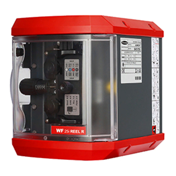
Page 34: Wf 25I Reel R /4R, Wf 30I Reel R /2R
Proper use The device is designed exclusively for wirefeeding in automated MIG/MAG welding applications in conjunction with Fronius system components. Any use above and beyond this purpose is deemed improper. The manufacturer shall not be held liable for any dam- age arising from such usage. - Page 35 40,0006,3035 Example: WF 30i REEL R /2R/G/W Do not dispose of used devices with domestic waste. Dispose of them according to the safety rules. Welding is dangerous. The following basic requirements must be met to ensure the equipment is used properly: Anyone performing automated welding must be sufficiently qualified Suitable protective equipment must be used All persons not involved must be kept at a safe distance from the wirefeeder and the...
- Page 36 Do not reach into the rotating cogs of the wire drive or into rotating drive components. Covers and side panels may only be opened / removed while maintenance or repair work is being carried out. Wear eye protection...
-
Page 37: Interconnecting Hosepack
Interconnecting hosepack General The interconnecting hosepack connects the power source to the wirefeeder. With the TPS/i welding system the interconnecting hosepack is available in two versions - one split and one standard variant. 3 / 5 / 10 / 15 m (extension - split variant) CON hosepacks 4 / 5.5 / 8 / 10 / 15 / 16 m (continuous variant) -
Page 38: Torch Hosepack
Torch hosepack General remarks The Robacta MHP hosepack is designed for gas-cooled and water-cooled robot applica- tions. It connects the TPS/i robot wirefeeders to the Robacta MTB robot welding torches. Scope of supply Robacta MHP PAP hosepack Robacta MHP conventional hosepack Robacta MHP hosepack Not supplied: Inner liners... -
Page 39: Crashbox /I
CrashBox /i General remarks CrashBox /i PAP fitted to robot arm CrashBox /i fitted to robot arm with clamp system The CrashBox /i is a protection device for the torch body, the drive unit, the wire brake and the torch body coupling. In the event of a collision, the CrashBox sends a signal to the robot control, which stops the robot immediately. -
Page 40: Application Areas
tional robot systems the torch hosepack runs along the robot arm and is attached to the clamp. In the event of a crash, the magnetic coupling smoothly deflects the forces along a large deflection path. Application areas The clamp system can be used for the following push robot hosepacks: MHP i G / MHP i W TPS /i hosepacks MTG/MTW TransSteel hosepacks Information on... -
Page 41: Clamp System Scope Of Supply And Options
Clamp system M8 hexagon nut scope of supply M8 washer and options Clamp Torque angle gauge M8 x 40 mm Allen screw Optional (material for extension): M8 x 40 mm screw M8 washer Extension Torque angle gauge (10) M8 hexagon nut... -
Page 42: Robot Welding Torch
Robot welding torch Safety CAUTION! Risk of burns from hot torch body, hot torch body coupling and other hot welding torch components. Before starting work on the torch body, the torch body coupling and all other welding torch components: ▶ Allow the torch body, torch body coupling and all other welding torch components to cool down to room temperature (+25 °C, +77 °F) ▶... -
Page 43: Controls, Connections And Mechanical Components
Controls, connections and mechan- ical components... -
Page 45: Control Elements And Mechanical Components
Control elements and mechanical components Safety WARNING! Danger from incorrect operation. This can result in severe personal injury and damage to property. ▶ All the functions described may only be used by trained and qualified personnel. ▶ Fully read and understand this document. ▶... - Page 46 Method 1 Retracting the wire electrode using the preset wire retract speed: Press and hold the wire retract button After pressing the wire retract button, the wire electrode is retracted by 1 mm (0.039 in.). After a short pause, the wirefeeder continues to retract the wire electrode - if the wire retract button remains pressed, the speed increases every second by 10 m/min (393.70 ipm) up to the preset wire retract speed.
- Page 47 wirefeeding will be stopped and the wire electrode will be retracted again by 1 mm (0.039 in.). NOTE! If there is a ground earth connection with the contact tip before the wire threading button is pressed, the wire electrode will be retracted when the button is pressed until it is short-circuit-free –...
-
Page 48: Wf 15I / 25I / 30I R
WF 15i / 25i / 30i R WF 15i R, WF 30i R connec- tions Function Welding torch connection Coolant connection For connecting the coolant connection socket from the interconnecting hosepack Coolant connection socket For connecting to the torch hosepack SpeedNet connection For connecting the SpeedNet cable from the interconnecting hosepack Shielding gas connection... -
Page 49: Wf 25I R Connections
Function Wire infeed (+) current socket For connecting the power cable from the interconnecting hosepack Shielding gas connection SpeedNet connection For connecting the SpeedNet cable from the interconnecting hosepack Coolant connection socket For connecting to the torch hosepack Coolant connection For connecting the coolant connection socket from the interconnecting hosepack Welding torch connection WF 25i R connec-... - Page 50 WF 25i R / L con- nections Function Wire infeed (+) current socket For connecting the power cable from the interconnecting hosepack Shielding gas connection SpeedNet connection For connecting the SpeedNet cable from the interconnecting hosepack Welding torch connection...
-
Page 51: Wf 15I / 25I / 30I R Pap
WF 15i / 25i / 30i R PAP WF 15i R PAP, WF 30i R PAP connections Function Welding torch connection (+) current socket For connecting the power cable from the interconnecting hosepack Shielding gas connection SpeedNet connection For connecting the SpeedNet cable from the interconnecting hosepack Coolant connection For connecting the coolant connection socket from the interconnecting hosepack Coolant connection socket... - Page 52 Function Welding torch connection (+) current socket For connecting the power cable from the interconnecting hosepack Shielding gas connection SpeedNet connection For connecting the SpeedNet cable from the interconnecting hosepack Wire infeed WF 25i R / L PAP connections Function SpeedNet connection For connecting the SpeedNet cable from the interconnecting hosepack Shielding gas connection...
-
Page 53: Wf 25I Reel R /4R, Wf 30I Reel R /2R
WF 25i REEL R /4R, WF 30i REEL R /2R Safety WARNING! Danger from incorrect operation. This can result in severe personal injury and damage to property. ▶ All the functions described may only be used by trained and qualified personnel. ▶... - Page 54 100 mm 3.9 in. 4 x M5 (13) (12) Top/underside Function Cover Protective cover for the 4-roller drive 4-roller drive Protective cover for the 2-roller drive 2-roller drive Opening for optional sash lock Control panel SpeedNet connection Blanking cover for optional component (10) Blanking cover for optional component (11)
-
Page 55: Control Panel
Control panel Function Operating status LED Shows steady green when the device is ready for use Gas-test button For setting the required gas flow rate on the pressure regulator Gas will flow out for 30 seconds after the gas-test button is pressed. - Page 56 Function Wire retract button For retracting the wire electrode with no accompanying flow of gas or current The wire electrode can be retracted using one of two methods: Method 1 Retracting the wire electrode using the preset wire retract speed: Press and hold "Wire retract"...
- Page 57 The wire electrode will be threaded 1 mm (0.039 in.) after the wire threading button is pressed After a short pause, the wirefeeder continues to thread the wire electrode. If the wire threading button remains pressed, the speed will increase every second at a rate of 10 m/min (393.70 ipm) until the preset feeder inching speed is reached If the wire electrode comes into contact with a ground earth connection, the...
-
Page 59: Installation - Conventional Robot
Installation - conventional robot... -
Page 61: Fitting The Welding System To A Conventional Robot
Fitting the welding system to a conventional robot Safety WARNING! Work that is carried out incorrectly can cause serious injury or damage. ▶ The following activities may only be carried out by trained and qualified personnel. ▶ The Operating Instructions for system components, particularly the chapter entitled "Safety rules", must be observed. -
Page 62: Fitting The Wire-Feed Unit
Fitting the wire-feed unit Fitting the NOTE! wirefeeder holder Depending on the robot, please also note the instructions and information on installing the wirefeeder in the User Information. Fitting the WF 15i / 25i / 30i R WF 25i / 30i R / L wirefeeder 2x M8 x 20 mm 2x M8 x 20 mm... - Page 63 NOTE! The coolant line must be routed under the wirefeeder. To do so, the wirefeeder must be removed from the holder and re-fitted after the line has been routed. Example: WF 25i R...
-
Page 64: Fitting The Crashbox /I To The Robot
Fitting the CrashBox /i to the robot Fitting the Crash- Observe the torques when fitting the robot Box /i to the flange: robot Max. tightening torque for screws of strength class 8.8 3.3 Nm / 2.43 lb-ft 5.0 Nm / 3.69 lb-ft 6.0 Nm / 4.43 lb-ft 27.3 Nm / 20.14 lb-ft 54 Nm / 39.83 lb-ft... -
Page 65: Installing The Crashbox/I Dummy On The Robot
Installing the Observe the torques when fitting the robot CrashBox/i flange: Dummy on the robot Max. tightening torque for screws of strength class 8.8 3.3 Nm / 2.43 lb-ft 5.0 Nm / 3.69 lb-ft 6.0 Nm / 4.43 lb-ft 27.3 Nm / 20.14 lb-ft 54 Nm / 39.83 lb-ft 93 Nm / 68.60 lb-ft... - Page 66 6 Nm / 4.43 lb-ft 3,3 Nm / 2.43 lb-ft...
-
Page 67: Fitting The Clamp System
Fitting the clamp system Special tilt angle The positioning of the welding torch in relation to the workpiece is divided into fixed for the welding angles by the torque angle gauge. Special angles are available on request. torch 12,5° 12,5° 34,5°... -
Page 68: Fitting The Clamp System
Fitting the clamp system 42 Nm 30.98 lb-ft Fitting the clamp 42 Nm system with 30.98 lb-ft extension 42 Nm 30.98 lb-ft... -
Page 69: Fitting The Mhp G / W Hosepack
Fitting the MHP G / W hosepack Fitting the MHP G / W conven- tional hosepack - Standard 6,5 Nm 4.79 lb-ft Optimum hosep- ack arrangement R < 200 mm R ≥ 200 mm... -
Page 70: Fitting The Tps/I Torch Neck
Fitting the TPS/i torch neck Safety CAUTION! Risk of burns from hot torch body, hot torch body coupling and other hot welding torch components. Before starting work on the torch body, the torch body coupling and all other welding torch components: ▶... -
Page 71: Fitting The Inner Liner Inside The Torch Hosepack
Fitting the inner NOTE! liner inside the torch hosepack Ensure that the hosepack is straight when fitting the inner liner, otherwise the liner might not be inserted correctly. Steel inner liner Plastic inner liner... - Page 72 Screw the clamping nipple onto the inner liner as far as it will go. The inner liner must be visible through the hole in the lock.
-
Page 73: Fitting The Interconnecting Hosepack
Fitting the interconnecting hosepack Fitting the Stand- ard interconnect- ing hosepack to the robot 3 Nm 2.21 lb-ft Connecting the CAUTION! extension hosep- Danger from electric current due to inadequate connections. This can result in serious injury and damage to property. ▶... -
Page 75: Connecting The Mhp W Hosepack
Connecting the MHP W hosepack Connecting the IMPORTANT! Whenever the torch hosepack is fitted or removed, ensure that the coup- MHP W hosepack ling point is clean and dry. Remove any coolant that has escaped from the coupling point. * Push in hosepack as far as it will go... - Page 76 IMPORTANT! Always route coolant hoses below the hosepack and then guide them to the connection socket: WFi R / SB 500i SB 60i...
- Page 77 Coolant return (red) Coolant flow (blue) IMPORTANT! Connect the coolant hoses to the cooling unit correctly! Disconnecting the coolant hoses PUSH...
-
Page 78: Connecting Wire-Feed Unit To System Components
Connecting wire-feed unit to system components Safety WARNING! An electric shock can be fatal. Before starting the work described below: ▶ Turn the power source mains switch to the "O" position ▶ Disconnect the power source from the mains ▶ Ensure that the power source remains disconnected from the mains until all work has been completed CAUTION! - Page 79 WF 15i / 30i R WF 25i R WF 25i / 30i R/L: WF 30i R / L WF 25i R / L...
- Page 80 IMPORTANT! After disconnecting the coolant connection from the hosepack, close the coolant connections on the hosepack using the hosepack's seal cap.
-
Page 81: Fitting The Opt / I Mhp Wirebrake And Torch Body
Fitting the OPT / i MHP WireBrake and torch body Safety CAUTION! Risk of burns from hot torch body, hot torch body coupling and other hot welding torch components. Before starting work on the torch body, the torch body coupling and all other welding torch components: ▶... -
Page 82: Technical Data
Technical data TCP offset 47 mm 1.85 in. Wire diameter 0.8 - 1.6 mm 0.03 - 0.06 in. Weight 450 g 0.99 Ib. Fitting the OPT/i MHP WireBrake 3 x 0,1 Nm 3 x 0.07 lb-ft ONLY when p > 5,5 bar / 79.74 psi NOTE! The front O-ring must only be removed at a system pressure of >... - Page 83 For steel inner liners: For plastic inner liners:...
-
Page 84: Removing The Opt / I Mhp Wirebrake And Torch Body
Removing the OPT / i MHP WireBrake and torch body Safety CAUTION! Risk of burns from hot torch body, hot torch body coupling and other hot welding torch components. Before starting work on the torch body, the torch body coupling and all other welding torch components: ▶... -
Page 85: Fitting The Unreeling Wirefeeder
In accordance with the Installation Instructions, mount the unreeling wirefeeder onto the wall bracket or the wire drum mount Use the QuickConnect option to connect the wirefeeding hose to the unreeling wirefeeder Use Fronius SpeedNet to connect the unreeling wirefeeder to the power source in the welding system... -
Page 87: Installation - Pap
Installation - PAP... -
Page 89: Fitting The Welding System To A Pap Robot
Fitting the welding system to a PAP robot Safety WARNING! Work that is carried out incorrectly can cause serious injury or damage. ▶ The following activities may only be carried out by trained and qualified personnel. ▶ The Operating Instructions for system components, particularly the chapter entitled "Safety rules", must be observed. - Page 90 Fourth robot axis: +/- 175° Fifth robot axis: +/- 90° fifth robot axis: +/- 120° - if the fourth robot axis = 0° and the sixth robot axis = 0° IMPORTANT! The maximum axis rotation of +/- 120° in the fifth robot axis only applies if there is NO axis rotation present in the fourth and sixth robot axes! Sixth robot axis: +/- 200°...
-
Page 91: Fitting The Wire-Feed Unit
Fitting the wire-feed unit Fitting the WF 15i/25i/30i R PAP... -
Page 92: Installing The Crashbox /I Pap On The Robot
Installing the CrashBox /i PAP on the robot Installing the Observe the torques when fitting the robot CrashBox /i PAP flange: on the robot Max. tightening torque for screws of strength class 8.8 3.3 Nm / 2.43 lb-ft 5.0 Nm / 3.69 lb-ft 6.0 Nm / 4.43 lb-ft 27.3 Nm / 20.14 lb-ft 54 Nm / 39.83 lb-ft... -
Page 93: Installing The Crashbox/I Dummy On The Robot
Installing the Observe the torques when fitting the robot CrashBox/i flange: Dummy on the robot Max. tightening torque for screws of strength class 8.8 3.3 Nm / 2.43 lb-ft 5.0 Nm / 3.69 lb-ft 6.0 Nm / 4.43 lb-ft 27.3 Nm / 20.14 lb-ft 54 Nm / 39.83 lb-ft 93 Nm / 68.60 lb-ft... - Page 94 3,3 Nm / 2.43 lb-ft 3 Nm / 2.21 lb-ft...
-
Page 95: Fitting The Mhpi/Mhp S G/W Pap Hosepack
Fitting the MHPi/MHP S G/W PAP hosepack Fitting the Robacta MHP G/W PAP hosep- 45,0200,1404 Special tool required IMPORTANT! Whenever the welding torch is fitted or removed, ensure that the coupling point is clean and dry. Remove any coolant that has escaped from the coupling point. -
Page 96: Opt / I Mhp Wirebrake" Option
14 ± 2 Nm 10.33 ± 1.48 lb-ft 18 ± 2 Nm 13.28 ± 1.48 lb-ft “OPT / i MHP If you would like to fit the “OPT / i MHP WireBrake” option, read the “Fitting the OPT / i WireBrake”... -
Page 97: Fitting The Inner Liner Inside The Torch Hosepack
Fitting the inner NOTE! liner inside the torch hosepack Ensure that the hosepack is straight when fitting the inner liner, otherwise the liner might not be inserted correctly. Steel inner liner Plastic inner liner... - Page 98 Screw the clamping nipple onto the inner liner as far as it will go. The inner liner must be visible through the hole in the lock.
-
Page 99: Fitting The Mhpi/Mhp S G/W Pap Sm Hosepack
Fitting the MHPi/MHP S G/W PAP SM hosepack Fitting the Robacta MHP G/W PAP SM 45,0200,1404 hosepack Special tool required IMPORTANT! Whenever the welding torch is fitted or removed, ensure that the coupling point is clean and dry. Remove any coolant that has escaped from the coupling point. -
Page 100: Opt / I Mhp Wirebrake" Option
3 x 2 Nm 3 x 1.48 lb-ft 18 ± 2 Nm 13.28 ± 1.48 lb-ft “OPT / i MHP If you would like to fit the “OPT / i MHP WireBrake” option, read the “Fitting the OPT / i WireBrake”... -
Page 101: Fitting The Inner Liner Inside The Torch Hosepack
Fitting the inner NOTE! liner inside the torch hosepack Ensure that the hosepack is straight when fitting the inner liner, otherwise the liner might not be inserted correctly. Steel inner liner Plastic inner liner... - Page 102 Screw the clamping nipple onto the inner liner as far as it will go. The inner liner must be visible through the hole in the lock.
-
Page 103: Fitting The Interconnecting Hosepack
Fitting the interconnecting hosepack Fitting the PAP NOTE! interconnecting The mounting of the holder for the interconnecting hosepack depends on the hosepack to the robot robot manufacturer and robot type. ▶ Mount the holder for the interconnecting hosepack according to the Installation Instructions for the respective robot. -
Page 104: Connecting The Extension Hosepack
Connecting the CAUTION! extension hosep- Danger from electric current due to inadequate connections. This can result in serious injury and damage to property. ▶ All cables, leads and hosepacks must be properly connected, undamaged, correctly insulated and adequately dimensioned. Only on water-cooled hosepack = Interconnecting hosepack = Extension hosepack... -
Page 105: Connecting The Interconnecting Hosepack
Connecting the interconnecting hosepack... -
Page 106: Connecting Wire-Feed Unit To System Components
Connecting wire-feed unit to system components Safety WARNING! An electric shock can be fatal. Before starting the work described below: ▶ Turn the power source mains switch to the "O" position ▶ Disconnect the power source from the mains ▶ Ensure that the power source remains disconnected from the mains until all work has been completed CAUTION! -
Page 109: Start-Up
Start-up... -
Page 111: Inserting/Replacing Feed Rollers
Inserting/replacing feed rollers General The feed rollers are not installed in the device when it is first delivered. In order to achieve optimum wire electrode feed, the feed rollers must be suitable for the diameter and alloy of the wire being welded. NOTE! Risk from inadequate feed rollers. -
Page 112: Wf 30I Reel 2R: Inserting/Replacing Feed Rollers For The 2-Roller Drive
WF 30i Reel 2R: inserting/repla- cing feed rollers for the 2-roller drive CAUTION! Risk of crushing due to exposed feed rollers. ▶ Always fit the protective cover of the 2-roller drive after changing feed rollers. -
Page 113: Inserting/Replacing Feed Rollers
Inserting/repla- CAUTION! cing feed rollers Danger from feed roller holders flying upwards. This can result in severe injuries. ▶ When unlocking the clamping lever, keep fingers away from the area to the left and right of the lever. CAUTION! Danger from exposed feed rollers. This can result in severe injuries. -
Page 115: Feeding In The Wire Electrode
Feeding in the wire electrode Insulated routing WARNING! of wire electrode to wirefeeder Risk of serious injury and damage or an inferior weld as a result of earth contact or short-circuit of a non-insulated wire electrode. ▶ In the case of automated applications, ensure that only an insulated wire electrode is routed from the welding wire drum, large wirefeeder spool or wirespool to the wirefeeder (e.g. - Page 116 CAUTION! Risk of injury due to springiness of spooled wire electrode. ▶ When inserting the wire electrode into the 4-roller drive, hold the end of the wire electrode firmly to avoid injuries caused by the wire springing back. CAUTION! Risk of injury from moving or rotating parts in the welding system. ▶...
-
Page 117: Setting The Contact Pressure
Setting the con- NOTE! tact pressure Set the contact pressure in such a way that the wire electrode is not deformed but nevertheless ensures proper wirefeeding. The standard contact pressure values can be found on the sticker on the 4-roller drive... -
Page 118: Start-Up
Start-up Requirements When commissioning the welding system, the following requirements must be met: All components are installed and connected as described in the "Installation" chapter All appropriate welding media is connected Feed rollers are inserted in wirefeeders or drive unit Wire electrode is threaded in Feed roller contact pressure is set Motor adjustment completed... -
Page 119: Troubleshooting, Maintenance And Disposal
Troubleshooting, maintenance and disposal... -
Page 121: Troubleshooting
Troubleshooting Safety WARNING! Danger due to work that has been carried out incorrectly. This can result in severe personal injury and damage to property. ▶ All the work described below must only be carried out by trained and qualified per- sonnel. - Page 122 Power source does not function Mains switch is on, but indicators are not lit up Cause: There is a break in the mains lead; the mains plug is not plugged in Remedy: Check the mains lead, ensure that the mains plug is plugged in Cause: Mains socket or mains plug faulty Remedy:...
- Page 123 Irregular wire feed speed Cause: Hole in the contact tip is too narrow Remedy: Use a suitable contact tip Cause: Faulty inner liner in welding torch Remedy: Check the inner liner for kinks, dirt, etc. Cause: The feed rollers are not suitable for the wire electrode being used Remedy: Use suitable feed rollers Cause:...
-
Page 124: Care, Maintenance And Disposal
Care, maintenance and disposal General Under normal operating conditions, the device requires only a minimum of care and maintenance. However, it is vital to observe some important points to ensure the welding system remains in a usable condition for many years. Safety WARNING! Danger due to work that has been carried out incorrectly. -
Page 125: Special Care Of O-Rings
When repeatedly connecting and disconnecting the coolant hoses on the torch hosep- ack, grease the O-rings regularly. Unless a special grease is specified for the O-rings, use the O-ring grease from Fronius with item number 40,0009,0044. Whenever the Whenever the welding torch or torch hosepack is changed, ensure that the coupling welding torch or point is clean and dry. -
Page 126: Recognising Faulty Wearing Parts
After replacing the inner liner: CAUTION! Risk of injury and damage from loose connections. ▶ All cables, leads and hosepacks must be properly connected, undamaged, correctly insulated and adequately dimensioned. Recognising faulty wearing parts... -
Page 127: Mtg D, Mtw D - Fitting Wearing Parts To The Torch Body
Insulating parts Burned-off outside edges, notches Nozzle fittings Burned-off outside edges, notches Heavily covered in welding spatter Spatter guard Burned-off outside edges, notches Contact tips Worn-out (oval) wire entry and wire exit holes Heavily covered in welding spatter Penetration on the tip of the contact tip Gas nozzles Heavily covered in welding spatter Burned-off outside edges... -
Page 128: Fitting Wearing Parts To The Torch Body - Mtw 700 I
Fitting wearing parts to the torch body - MTW 700 i Removing the CrashBox PAP from the robot (without mount- ing key) -
Page 130: Removing The Crashbox Pap From The Robot (With Mounting Key)
Removing the CrashBox PAP from the robot (with mounting key) -
Page 132: Changing The Torch Hosepack, Changing The Interconnecting Hosepack
Changing the If a robot wirefeeder or a media splitter is mounted in the third robot axis, take the follow- torch hosepack, ing into account when changing the torch hosepack or interconnecting hosepack: changing the interconnecting CAUTION! hosepack Risk of damage to the robot wirefeeder or media splitter from escaping coolant. ▶... -
Page 133: Cleaning The Welding Torch
Cleaning the welding torch Disposal Dispose of in accordance with the applicable national and local regulations. -
Page 135: Technical Data
Technical data... -
Page 137: Wf Wire-Feed Unit
60% D.C.* 600 A 100% D.C.* 500 A Maximum shielding gas pressure 7 bar / 101.53 psi Coolant Original Fronius Maximum coolant pressure 5 bar / 72.53 psi Wire speed 0.5 - 15 m/min / 19.68 - 590.55 ipm Wire drive... -
Page 138: Wf 30I R, Wf 30I R Pap, Wf 30I R / L
60% D.C.* 600 A 100% D.C.* 500 A Maximum shielding gas pressure 7 bar / 101.53 psi Coolant Original Fronius Maximum coolant pressure 5 bar / 72.53 psi Wire speed 1 - 30 m/min / 39.37 - 1181.10 ipm Wire drive... -
Page 139: Unreeling Wirefeeder Wf Reel
Unreeling wirefeeder WF REEL WF 25i REEL Supply voltage 24 V DC / 60 V DC R /4R/G/W Nominal current 0.5 A / 1.2 A Wire speed 1 - 25 m/min 39.37 - 984.25 ipm. Wire drive 4-roller drive Wire diameter 0.8 - 2.4 mm 0.03 - 0.09 in. -
Page 140: Crashbox /I
CrashBox /i Technical data, triggering torques and weight/distance diagram Item numbers CrashBox /i 44,0350,3589 CrashBox /i XL 44,0350,3760 CrashBox /i XXL 44,0350,3380 CrashBox /i PAP 44,0350,3663 CrashBox /i PAP XL 44,0350,3759 CrashBox /i PAP XXL 44,0350,0202 Reset accuracy (1) ± 0.05 mm Maximum deflection in x/y direction CrashBox /i ~ 45°... - Page 141 CrashBox /i PAP XXL 750 g Dimensions CrashBox /i Ø90 mm x 60 mm CrashBox /i XL Ø90 mm x 60 mm CrashBox /i XXL Ø90 mm x 60 mm CrashBox /i PAP Ø90 mm x 40 mm CrashBox /i PAP XL Ø90 mm x 40 mm CrashBox /i PAP XXL Ø90 mm x 40 mm...
- Page 142 Triggering torques and weight/distance diagram The specified values only apply in a static state!
-
Page 143: Torch Hosepack
Torch hosepack MHP 400i G / R I (ampere) 10 min/40°C 40% D.C.* / 400 M21 (EN 439) 60% D.C.* / 320 100% D.C.* / 260 I (ampere) 10 min/40°C 60% D.C.* / 400 C1 (EN 439) 100% D.C.* / 320 [mm] 0.8 - 1.6 Ø... -
Page 144: Mhp 700I W / R (0.95 - 2.25 M / 3.12 - 7.38 Ft.)
MHP 700i W / R I (ampere) 10 min/40°C 100% D.C.* / 700 (0.95 - 2.25 m / M21 (EN 439) 3.12 - 7.38 ft.) I (ampere) 10 min/40°C 100% D.C.* / 700 C1 (EN 439) [mm] 0.8-1.6 (0.031-0.063) Ø [in.] 0.95 / 1.10 / 1.25 / 1.45 / 1.75 / 1.95 / 2.25 [ft. - Page 145 MHP 700i W / R I (ampere) 10 min/40°C 60% D.C.* 700 (3.25 - 4.25 m / M21 (EN 439) 100% D.C.* 580 10.66 - 13.12 ft.) I (ampere) 10 min/40°C 60% D.C.* 700 C1 (EN 439) 100% D.C.* 580 0.8-1.6 (0.031-0.063) [mm] Ø...
-
Page 146: Mhp 700I W / R / Pap
MHP 700i W / R / I (ampere) 10 min/40°C 100% D.C.* / 700 M21 (EN 439) I (ampere) 10 min/40°C 100% D.C.* / 700 C1 (EN 439) [mm] 0.8 - 1.6 Ø 0.031 - 0.063 [in.] 0.93 / 0.96 / 1.04 / 1.06 / 1.09 / 1.12 / [ft. -
Page 147: Robot Welding Torch
Robot welding torch Gas-cooled robot MTB 250i G/R (TX, TXM) welding torches X / I (10 min/40 °C) 40% D.C.* / 250 A 60% D.C.* / 200 A M21 (EN 439) 100% D.C.* / 170 A X / I (10 min/40 °C) 60% D.C.* / 250 A C1 (EN 439) 100% D.C.* / 200 A... -
Page 148: Water-Cooled Robot Welding Torches
MTB 400i G/R (TX, TXM) X / I (10 min/40 °C) 40% D.C.* / 400 A 60% D.C.* / 320 A M21 (EN 439) 100% D.C.* / 260 A X / I (10 min/40 °C) 60% D.C.* / 400 A C1 (EN 439) 100% D.C.* / 320 A [mm]... - Page 149 MTB 500i W/R (TX, TXM) X / I (10 min/40 °C) 100% D.C.* / 500 A M21 (EN 439) X / I (10 min/40 °C) 100% D.C.* / 500 A C1 (EN 439) 1.0-1.6 [mm] Ø [in.] 0.039-0.063 MTB 700i W/R (TX, TXM) X / I (10 min/40 °C) 100% D.C.* / 700 A...
-
Page 150: Interconnecting Hosepacks
Interconnecting hosepacks HP 70i Welding current at 10 min/40 °C (104 °F) 40% D.C.* / 400 A 60% D.C.* / 365 A 100% D.C.* / 320 A D.C. = Duty cycle HP 95i Welding current at 10 min/40 °C (104 °F) 40% D.C.* / 500 A 60% D.C* / 450 A 100% D.C.* / 360 A... - Page 152 FRONIUS INTERNATIONAL GMBH Froniusstraße 1 A-4643 Pettenbach AUSTRIA contact@fronius.com www.fronius.com Under www.fronius.com/contact you will find the addresses of all Fronius Sales & Service Partners and locations...
Need help?
Do you have a question about the TPS/i Push and is the answer not in the manual?
Questions and answers