Advertisement
Quick Links
Crosby_ReliefValve_800_900_iom_D498
Crosby Valve Inc.
Installation, Maintenance and Adjustment Instruction for Crosby
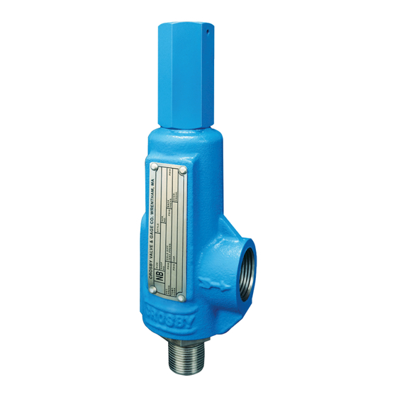
Adjustable Blowdown and Series 900 OMNI-TRIM
SERIES 800
GENERAL
®
Crosby
valves have been tested and adjusted at the factory. As service
conditions differ it may be necessary to make slight adjustments. These
adjustments are easily made if the instructions below are carefully
followed.
Warning: To have trouble free performance be sure to thoroughly
clean the inlets and outlets of valves before installing.
STORAGE AND HANDLING
Valves are often on hand at the job site months before they are installed.
Unless properly stored and protected, valve performance may be ad-
versely affected. Rough handling and dirt may damage or cause misalign-
ment of the valve parts. It is recommended that the valves be left in their
original shipping containers and that they be stored in a warehouse or as
a minimum on a dry surface with a protective covering until they are used.
Pressure relieving valves must be handled carefully and never
subjected to sharp impact loads. They should not be struck, bumped
or dropped. Rough handling may alter the pressure setting, deform valve
parts and adversely affect seat tightness and valve performance.
NOTE: Where valves have levers as in Types D and E Top Con-
struction, DO NOT LIFT OR CARRY VALVES BY THE LEVERS!
Inlet and outlet protectors should remain in place until the valve is ready
to be installed on the system.
INSTALLATION
– Inlet Piping
The valve should be mounted vertically in an upright position either
directly on a nozzle from the pressure vessel or on a short connection
fitting that provides a direct, unobstructed flow between the vessel and the
valve. Installing a pressure relief valve in other than this recommended
position might adversely affect its operation.
A valve should never be installed on a fitting having a smaller
inside diameter than the inlet connection of the valve.
Compliance with the above recommendations will assure clean positive
valve operation.
Many valves are damaged when first placed in service because of failure
to clean the connections properly when installed.
Both the valve inlet and the vessel and/or line on which the valve
is mounted must be thoroughly cleaned of all dirt and foreign
material.
– Outlet Piping
Discharge piping should be simple and direct. A broken connection near
the valve outlet is preferred. The weight of the discharge piping should be
carried by a separate support and be firmly braced against swaying or
vibrations.
Fittings or pipe having a smaller inside diameter than the valve
outlet connections must not be used. The flow from the valve
must discharge to a safe disposal area.
THE SAFETY OF LIVES AND PROPERTY OFTEN DEPENDS ON
THE PROPER OPERATION OF THE PRESSURE RELIEF VALVES.
THE VALVES MUST BE MAINTAINED ACCORDING TO APPRO-
PRIATE INSTRUCTIONS AND MUST BE PERIODICALLY TESTED
AND RECONDITIONED TO ENSURE THAT THEY FUNCTION
CORRECTLY.
®
Crosby
Pressure Relief Valves described in this instruction are
manufactured in accordance with the requirements of ASME Boiler
and Pressure Vessel Code, Section VIII. Capacities are certified by the
Instruction No. IS-V3117
Effective: April 1998
®
Pressure Relief Valves
Cap
Spindle
Adjusting Bolt
Adjusting Bolt Nut
Spring Washer (Top)
Spring
Spring Washer
(Bottom)
Guide
Disc Holder
Set Screw
Set Screw Gasket
Disc Insert
Adjusting Ring
Cylinder
Base
Threaded Connection
Series 800
Cap
Spindle
Adjusting Bolt
Adjusting Bolt Nut
Spring Washer
(Top)
Spring
Spring Washer
(Bottom)
Guide
Disc Holder
Disc Insert
Cylinder
Base
Threaded Connection
Series 900
®
Series 800
SERIES 900
Seal & Wire
O-Ring
O-Ring Soft Seat
Metal-To-Metal Seat
Seal & Wire
O-Ring
O-Ring Soft Seat
Metal-To-Metal Seat
Advertisement

Summary of Contents for Crosby OMNI-TRIM 900 Series
- Page 1 Crosby_ReliefValve_800_900_iom_D498 Crosby Valve Inc. Instruction No. IS-V3117 Effective: April 1998 Installation, Maintenance and Adjustment Instruction for Crosby ® Series 800 ® Adjustable Blowdown and Series 900 OMNI-TRIM Pressure Relief Valves SERIES 800 SERIES 900 GENERAL ® Crosby valves have been tested and adjusted at the factory. As service conditions differ it may be necessary to make slight adjustments.
- Page 2 The new spring and washers must be obtained from LAPPING OF SEATS – METAL SEATED VALVES ONLY Crosby and the valve must be reset and the nameplate restamped by Many different methods exist for lapping valve seats but certain essential an authorized repair facility.
- Page 3 MAINTENANCE – ASSEMBLY ASSEMBLY OF CAPS AND LIFTING LEVER DEVICES 1) Prior to assembly, the following parts are to be coated with a lubricant/ sealant such as pure nickel “Never-Seez” or equivalent. Other lubri- Type A (Screwed Cap) cants/sealants can be used depending on service conditions. Apply pure nickel Never-Seez or equivalent to the cap sealing surface and screw the cap onto the top of the cylinder.
- Page 4 WARRANTY Ordering Information Crosby Valve Inc., Crosby Valve and Engineering Division, Crosby Valve Pte. Ltd., Crosby Valve Ltd. or Crosby Valve Sales and Service Corporation (collectively "Crosby") hereby warrants that Crosby recommends that a sufficient inventory of spare the goods delivered under contract will be free from defect in parts be maintained to support process requirements.
Need help?
Do you have a question about the OMNI-TRIM 900 Series and is the answer not in the manual?
Questions and answers