Table of Contents
Advertisement
Quick Links
Advertisement
Table of Contents

Related Manuals for LMI Technologies Chroma+scan 21X5


Summary of Contents for LMI Technologies Chroma+scan 21X5
- Page 1 Chroma+scan 21X5 Version 4.11.3.0...
- Page 2 This document, submitted in confidence, contains proprietary information which shall not be reproduced or transferred to other documents or disclosed to others or used for manufacturing or any other purpose without prior written permission of LMI Technologies Inc. No part of this publication may be copied, photocopied, reproduced, transmitted, transcribed, or reduced to any electronic medium or machine readable form without prior written consent of LMI Technologies, Inc.
-
Page 3: Table Of Contents
User Precautions & OEM Responsibilities ..........7 1.2.3 Class 3B/lllb OEM Responsibilities ............. 7 Requirements for Laser Systems Sold or Used In the USA ....... 9 Chroma+scan 21X5 Laser Safety Specification ..........9 Sensor Overview ....................10 Introduction ..................... 12 Measurement Principles .................. 12 Sensor Specifications ..................... - Page 4 5.3.2 System Calibration Coefficients..............40 5.3.3 Speeds and Data Rates ................40 5.3.4 Modes and Messages ................41 5.3.4.1 Video Mode ..................41 5.3.4.2 Free Mode ..................43 5.3.4.3 Calibration Mode ................45 5.3.4.4 Detection Mode ................. 46 5.3.4.5 Web Mode ..................47 5.3.5 Health Indicators ..................
-
Page 5: Laser Safety
Section 1 Section 1 1 Laser Safety 1.1 General Information The laser light sources used in LMI Sensors are semiconductor lasers emitting visible light. LMI Laser Sensors have a 2/ll, 3R/llla or 3B/lllb classification depending on model. Class 2/ll and 3R/llla sensors are referred to as “products” indicating that they fully comply with the standards relating to laser products specified in IEC 60825-1 and U.S. -
Page 6: Laser Classification
1. International Standard IEC 60825-1 (2001-08) Consolidated edition, Safety of laser products – Part 1: Equipment classification, requirements and user’s guide 2. Technical Report TR 60825-10, safety of laser products – Part 10. Application guidelines and explanatory notes to IEC 60825-1 3. -
Page 7: User Precautions & Oem Responsibilities
** in the table above. These items must be added and completed by the OEM in the system design. 1.2.3 Class 3B/lllb OEM Responsibilities LMI Technologies has filed reports with the FDA to assist the OEM in achieving certification of their laser products. The OEM can reference these reports by an accession number that will be provided upon request. - Page 8 Remote Interlock A remote interlock connection must be present in Class IIIB laser systems. This permits remote switches to be attached in serial with the keylock switch on the controls. The deactivation of any remote switches must prevent power from being supplied to any lasers.
-
Page 9: Requirements For Laser Systems Sold Or Used In The Usa
1.3 Requirements for Laser Systems Sold or Used In the USA The OEM’s laser system which incorporates laser components or laser products manufactured by LMI Technologies requires certification by the FDA. It is the responsibility of the OEM to achieve and maintain this certification. - Page 10 2.1.2 Shielded Cable LMI Technologies recommends the use of shielded cables in all environments to ensure isolation from electrical noise. The shield should be electrically connected to both the sensor housing through the connector housing and to the electrical box containing either the Master (network systems) or the power supply (standalone sensors).
- Page 11 2.1.4 Uninterruptible Power Supply (UPS) To maximize the life of the sensor, LMI Technologies recommends the use of an on-line double-conversion UPS whenever the quality of the electrical supply to the system is poor. This includes but is not limited to when the electrical supply: contains high frequency noise (due to other electronics, electic motors or other •...
-
Page 12: Sensor Overview
Gigabit Ethernet. 3.2 Measurement Principles The chroma+scan 21X5 sensors function on the principle of structured light triangulation. A semiconductor laser with special optics projects fan of light onto the target. A digital camera mounted at an angle to the laser plane acquires images of the light pattern created on the target. -
Page 13: Sensor Specifications
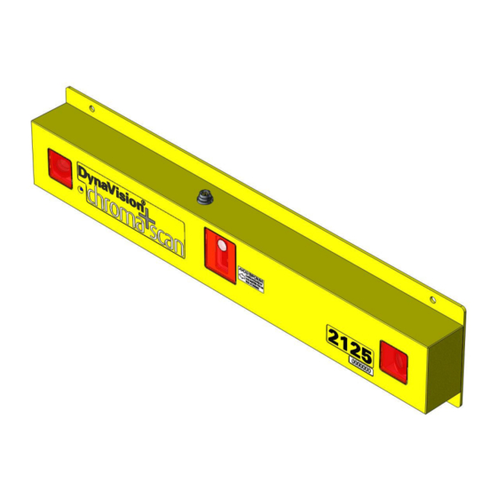
This section presents sensor specific chroma+scan 21X5 information. It describes the different models, and gives dimensions of the scan zone and sensor. 4.1 Models Currently, chroma+scan 2125 is the only one model in the chroma+scan 21X5 sensor family. 4.1.1 chroma+scan 2125... -
Page 14: Coordinate Definitions
4.2 Coordinate Definitions Throughout this document and software interface, displacements are represented in x-, y- and/or z-coordinates. The coordinates are defined as follows: Axis Definition Field of view (along the laser line) Field of view (axis of motion or axis of time) Range from a sensor to the object being scanned. -
Page 15: Performance
4.3 Performance Range Accuracy ±1.3 mm ±0.050 in Profile Resolution 3.0 mm 0.120 in Scan Resolution @ 4.5m/s (900 fpm) chroma+scan 2125 9.2 mm 0.360 in • Scan Rate chroma+scan 2125 500 Hz • 4.4 Specifications Operating Temperature 0 - 50°C 32 - 122°F Input Power +48VDC... -
Page 16: Scan Zone
4.5 Scan Zone Clearance Distance (CD) 584 mm 23.0 in Measurement Range (MR) 940 mm 37.0 in Field of View (FOV) @ CD 498 mm 19.6 in Field of View (FOV) @ CD + MR 1219 mm 48.0 in... -
Page 17: Dimensions
4.6 Dimensions The sensor can be mounted with either M8 or 5/16" hardware. Provision to adjust the position and orientation of the sensor to align its laser plane with the laser planes of the other sensors in the ring is recommended. Although this alignment is not required for reliable profile data (adjacent sensors typically scan during different time slices), aligned laser planes provide a better appearance to the end user of the system. -
Page 18: Cleaning
4.9 Features The chroma+scan 21X5 is the new-generation, high-speed, high-density 3D profile scanning system for primary log optimization. Binocular scanning provides complete 3D profiles unobstructed by protruding knots and log features. Normalized intensity data... -
Page 19: Binocular 3D Scanning
4.9.2 High Scan Rates The chroma+scan 21X5 sensor family provides scan rates up to 500Hz. At the same time, the sensors maintain excellent dark wood performance and ambient light immunity. -
Page 20: System
Section 5 5 System A chroma+scan 21X5 system consists of following components: 1. Network components: a. FireSync Master 400/800/1200/2400 b. Station computer (Host computer) c. Client computer d. Network switch e. 48V power supply FireSync network cordsets g. Other cabling: ethernet, power & encoder 2. - Page 21 Currently, Detection Mode only supports a single ring of sensors. The scan frame mechanically supports the sensors, and should provide a means of adjusting the location and orientation of each sensor so that their laser planes can be aligned. This is not required to eliminate interference between adjacent sensors (typically the system is set up with adjacent sensors scanning during different slices of the scan period).
-
Page 22: Calibration Target
5.4 Calibration Target The system calibration target is required to perform a system calibration. This process locates each sensor with respect to a global coordinate system defined relative to the target. Transformation parameters for each sensor in the system are acquired during the system calibration process and are used by the Station to transform profile data from the multiple sensors into a single coordinate system aligned with the downstream log processing equipment (eg saws, chipper heads). -
Page 23: Software
The FireSync Client application is available for Windows XP. Obtain the software from LMI Technologies Downloads site and install it on a suitable Client machine. The Client machine should have a Gigabit Ethernet adaptor that can be configured for a static IP address. -
Page 24: Connection
After connecting, the server will be displayed as “Server S/N 0”. This means that the Station is new from the factory and has not had the chroma+scan 21X5 software installed on it. The next step is to upgrade the server. Select the server, then select Upgrade from the Server menu. - Page 25 The system topology is now shown in the top left corner of the application. The center part of the application shows configuration tabs, and the right half of the application is occupied by visualization tabs. Selecting the Server entry in the device tree will bring up system level configuration tabs to the right.
- Page 26 Orientation is a value that can be 0 or 1. This indicates the sensor's orientation relative to the scanning direction. If the model number label on the sensor is towards the out feed of the system, the value should be set to 1, otherwise 0. Multiplex is a value that can be 0 to 3.
-
Page 27: Firesync Client Options
6.2.5 FireSync Client Options 6.2.5.1 Video Tab Select a sensor in the device tree, and then select the Video tab. Press the Play button (black triangle) in the toolbar, and observe the incoming video images from each profile camera (Video-0, Video-1 tabs). If there is an object within the field of view of the sensors, you will see laser images appear in the display. -
Page 28: Free Tab
6.2.5.2 Free Tab Select the server in the device tree, and then select the Free tab. Press the Play button (black triangle) in the toolbar, and observe the incoming profile data from each sensor. You can right-click on the graphic display for options. Note that there is also a Free tab for each sensor in the device list. - Page 29 ERROR: ioerror OFFENDING COMMAND: image STACK:...
Need help?
Do you have a question about the Chroma+scan 21X5 and is the answer not in the manual?
Questions and answers