
Related Manuals for Shimano Nexus INTER 5E SG-C7000-5V


Summary of Contents for Shimano Nexus INTER 5E SG-C7000-5V
- Page 1 S E R V I C E M A N U A L SG-C7000-5V SG-C7000-5R SG-C7000-5C SG-C7000-5D SG-C7050-5V SG-C7050-5R SG-C7050-5C SG-C7050-5D Ver.1.0 ©Jul. 2019 by Shimano Inc. ITP...
- Page 2 CONTENTS Introduction of INTER-5E ……………………………………………………………………………………………… Dealer's Manual ……………………………………………………………………………………………………………………… SG-C7000-5V, SG-C7000-5R, SG-C7000-5C, SG-C7000-5D • INSTALLATION • ADJUSTMENT • MAINTENANCE SG-C7050-5V, SG-C7050-5R, SG-C7050-5C, SG-C7050-5D • INSTALLATION • CONNECTION OF THE ELECTRIC WIRES • MAINTENANCE Troubleshooting ………………………………………………………………………………………………………………………...
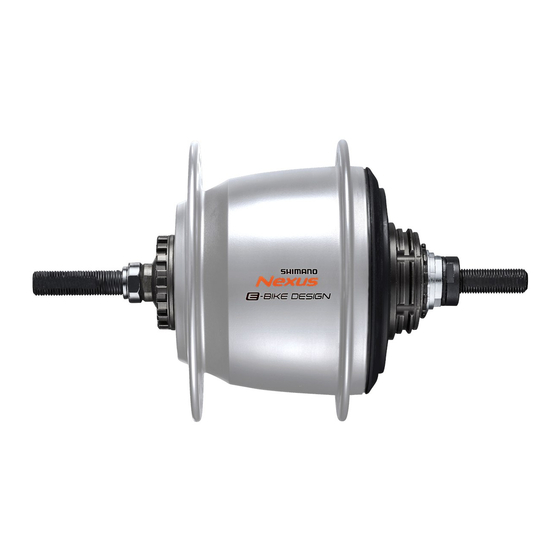
- Page 3 Return to index page Introduction of INTER-5E E-BIKE Dedicated Internal Geared Hub The NEXUS Inter-5E is a revolutionary internal geared hub designed specifically for the unique demands of E-BIKE riding. It can withstand much higher pedaling forces, even while shifting (+180% compare with SG-C6000 series) by optimizing shift pattern design .
- Page 4 Also, riders can always manually shift into the gear they want, even in auto mode. When they do, the SHIMANO STEPS system uses a learning function to recognize the manual shift operation and automatically fine-tunes future automatic shift timing to the rider's liking.
- Page 5 Return to index page Dealer's Manual SG-C7000-5V SG-C7000-5R SG-C7000-5C SG-C7000-5D...
- Page 6 Next, install the sprocket and secure it in place with the snap ring. Right-hand dust cap C Driver Applicable sprockets Right-hand dust cap A Specifications Outward assembling Inward assembling INTER-5E 24T, 27T, 30T 24T, 27T, 30T Click here for the latest Dealer's Manual https://si.shimano.com/DM/CASG002...
- Page 7 Should be aligned Install it with the red marks (z) on the Cassette joint cassette joint aligned with the red marks (z) on the right side of the hub body. Click here for the latest Dealer's Manual https://si.shimano.com/DM/CASG002...
- Page 8 (z) with the yellow mark (z) on the pulley of the cassette joint. Turn the cassette joint mounting ring 45° Cassette joint mounting ring clockwise. Bracket Hold down the bracket securely when performing work. Click here for the latest Dealer's Manual https://si.shimano.com/DM/CASG002...
- Page 9 M brake, and then provisionally tighten the brake unit fixing nut. „ Installation of the hub to the frame Mount the chain on the sprocket, and Hub axle then set the hub axle into the dropout. Dropout Click here for the latest Dealer's Manual https://si.shimano.com/DM/CASG002...
- Page 10 20°≤ ϴ ≤38° 7R/Black 7L/Gray ϴ =0° Reversed 6R/Silver 6L/White Reversed ϴ =0° 5R/Yellow 5L/Brown (Full chain case) ϴ =60° - 90° Vertical 8R/Blue 8L/Green Note: Vertical type does not include the coaster specifications Click here for the latest Dealer's Manual https://si.shimano.com/DM/CASG002...
- Page 11 Take up slack in the chain and secure the Hub nut wheel to the frame with the cap nut. Tightening torque 30 - 45 N·m NOTICE Check that the wheel is fixed securely to the frame with the hub nut. Click here for the latest Dealer's Manual https://si.shimano.com/DM/CASG002...
- Page 12 Use a lock nut with a nylon insert (self-locking nut) as the clip nut. • It is recommended that Shimano made clip bolts, clip nuts, and arm clips be used. • If the clip nut comes off the brake arm, or...
- Page 13 Dealer’s Manual (SG-C7000-5V / SG-C7000-5R / SG-C7000-5C / SG-C7000-5D) „ Installation of the disc brake rotor Center lock type Disc brake rotor Disc brake rotor fixing lock ring TL-LR10 Tightening torque 40 N·m Click here for the latest Dealer's Manual https://si.shimano.com/DM/CASG002...
- Page 14 166 mm or more Tightening torque Ø22.2 mm 2 - 2.5 N·m TECH TIPS • If using Shimano half grip, the straight section of the handlebar should be 166 mm or longer. Attach the REVOSHIFT lever to this straight section. •...
- Page 15 Set SL-C7000-5 to 5. REVOSHIFT lever If rubber bellows and a rubber cover are Rubber bellows attached, install the rubber cover and Outer casing holder rubber bellows to the outer casing Rubber cover holder. Click here for the latest Dealer's Manual https://si.shimano.com/DM/CASG002...
- Page 16 Outer casing holder rubber cover and set it into the outer Outer casing casing holder. Rubber bellows Push the outer casing so that it securely touches the holder. Rubber cover Click here for the latest Dealer's Manual https://si.shimano.com/DM/CASG002...
- Page 17 When installing the inner cable fixing bolt unit, use the setting tool TL-S700-B. Turn the lever of the pulley clockwise. Pulley lever In the following steps 9 and 11, continue to work in this condition. Click here for the latest Dealer's Manual https://si.shimano.com/DM/CASG002...
- Page 18 (toward the dropout), and then slide the flats part (y) of the inner cable fixing washer into the gap (z) in the pulley. Turn the cable 60˚ counterclockwise and Hook attach it to the hook. Click here for the latest Dealer's Manual https://si.shimano.com/DM/CASG002...
- Page 19 Outer casing holder unit outer casing holder unit into the outer casing holder of the cassette joint (z). Pulley Bracket NOTICE Check that the inner cable is correctly seated inside the pulley guide. Guide Guide Click here for the latest Dealer's Manual https://si.shimano.com/DM/CASG002...
- Page 20 (z). Be careful not to Rubber bellows damage the rubber bellows at this time. Rubber cover NOTICE Check that the inner cable is correctly seated inside the pulley guide. Guide Guide Click here for the latest Dealer's Manual https://si.shimano.com/DM/CASG002...
- Page 21 If you over-shift, the setting line will not return to the proper position, and the setting lines may not be aligned at the correct position. (Refer to procedure 3) Click here for the latest Dealer's Manual https://si.shimano.com/DM/CASG002...
- Page 22 Use the one that is easiest to see. When the bicycle is upright Should be aligned Pulley Bracket When the bicycle is upside down Pulley Should be aligned Bracket Click here for the latest Dealer's Manual https://si.shimano.com/DM/CASG002...
- Page 23 After adjusting the cassette joint, cut off Inner end cap the excess length of inner cable. Next, install the inner end cap. 15 - 20 mm Click here for the latest Dealer's Manual https://si.shimano.com/DM/CASG002...
- Page 24 Remove the inner cable fixing bolt unit Inner cable fixing bolt unit from the cassette joint pulley. Cassette joint pulley NOTICE If reinstalling the cable, refer to steps 9 to 11 in "Cassette joint end". Detach the wheel. Click here for the latest Dealer's Manual https://si.shimano.com/DM/CASG002...
- Page 25 Loosen the cover fixing screw. Cover fixing screw Remove the cover. Cover Remove the inner cable mounting bolt Inner cable mounting bolt unit unit from the cassette joint pulley. Cassette joint pulley Click here for the latest Dealer's Manual https://si.shimano.com/DM/CASG002...
- Page 26 Next, pull the inner cable so that the inner cable drum fits into the recess in the winder unit. Replace the cover and tighten the cover Cover fixing screws. Cover fixing screw Tightening torque 0.1 - 0.25 N·m Click here for the latest Dealer's Manual https://si.shimano.com/DM/CASG002...
- Page 27 Also, for carrying out maintenance, the use of Shimano internal geared hub grease or a lubrication kit is recommended. If Shimano grease or a Shimano lubrication kit is not used, problems such as a malfunction in gear shifting may occur.
- Page 28 Return to index page Dealer’s Manual (SG-C7000-5V / SG-C7000-5R / SG-C7000-5C / SG-C7000-5D) Remove the internal unit from the oil. Let excess oil drain off for approximately 60 seconds. Reassemble the hub. Click here for the latest Dealer's Manual https://si.shimano.com/DM/CASG002...
- Page 29 Return to index page Dealer's Manual SG-C7050-5V SG-C7050-5R SG-C7050-5C SG-C7050-5D...
- Page 30 (SG-C7050-5V / SG-C7050-5R / SG-C7050-5C / SG-C7050-5D) INSTALLATION Refer to the internal geared hub-compatible SHIMANO STEPS dealer’s manual for information on installing parts not listed in this document. Installation of sprocket to the hub Place right-hand dust cap onto the driver Snap ring on the right side of the hub body.
- Page 31 Only MU-UR500 can be used with SG-C7050. ● mark (red) Should be aligned TECH TIPS If the two ● marks (red) are not aligned, use the TL-SGE1 to align the two ● marks (red). Turn clockwise TL-SGE1 Click here for the latest Dealer's Manual https://si.shimano.com/DM/CASG003...
- Page 32 If the motor unit is installed off the initial position, some gears may become unavailable and the hub or the motor unit may be damaged. Click here for the latest Dealer's Manual https://si.shimano.com/DM/CASG003...
- Page 33 This is the mark for which the of the motor unit. position was aligned in step 1. Motor unit guide hole Outer side Right-hand lock nut guide Click here for the latest Dealer's Manual https://si.shimano.com/DM/CASG003...
- Page 34 Disc brake rotor installation ring TL-LR10 Tightening torque 40 N·m „ Installation of the hub to the frame Mount the chain on the sprocket, and then set the hub axle into the dropout. Dropout Hub axle Click here for the latest Dealer's Manual https://si.shimano.com/DM/CASG003...
- Page 35 For right For left hub axle. θ≤20° 5R/Yellow 5L/Brown Standard θ≤38° 7R/Black 7L/Gray θ=0° Reversed 6R/Silver 6L/White Reversed θ=0° 5R/Yellow 5L/Brown (Full chain case) θ=60° - 90° Vertical 8R/Blue 8L/Green Click here for the latest Dealer's Manual https://si.shimano.com/DM/CASG003...
- Page 36 • When installing parts such as a mudguard stay to the hub axle, install them in the order shown in the illustration below. Non-turn washer Mudguard stay Carrier stay Washer Hub nut Click here for the latest Dealer's Manual https://si.shimano.com/DM/CASG003...
- Page 37 Return to index page Dealer’s Manual (SG-C7050-5V / SG-C7050-5R / SG-C7050-5C / SG-C7050-5D) For coaster brakes Brake arm (A) (B) Clip nut Clip bolt Chainstay Arm clip Click here for the latest Dealer's Manual https://si.shimano.com/DM/CASG003...
- Page 38 (SG-C7050-5V / SG-C7050-5R / SG-C7050-5C / SG-C7050-5D) CONNECTION OF THE ELECTRIC WIRES Refer to the internal geared hub-compatible SHIMANO STEPS dealer’s manual for information on connecting electric wires to parts not listed in this document. „ Connection to motor unit...
- Page 39 After connecting the electric wires to all of the components, install the battery and check the operation. Check that gear-shifting of the rear can be performed properly by operating the shifting switch. Click here for the latest Dealer's Manual https://si.shimano.com/DM/CASG003...
- Page 40 NOTICE MU-UR500 Use the wide end of the TL-EW02 Shimano original tool to disconnect the Use the wide end of the TL-EW02 Shimano electric wires. original tool to disconnect the electric wires. If you pull too firmly, problems with operation may occur.
- Page 41 PROJECT. (Japanese/English/German/French/Italian/ Chinese/Dutch/Spanish) Download the latest version of E-TUBE PROJECT from the support website. (http://e-tubeproject.shimano.com) Connect SM-PCE1, SM-PCE02, or SM-BCR2. Connect the battery when connecting SM-BCR2. Activate the adjustment setting mode in E-TUBE PROJECT. Check that the adjustment value is set to 0 (default) in E-TUBE PROJECT [A].
- Page 42 Continue adjusting the value by one in the same direction until the abnormal noise or unusual feels are eliminated. Finally, ride the bicycle to check whether there is no problem. Click here for the latest Dealer's Manual https://si.shimano.com/DM/CASG003...
- Page 43 Value is set to other abnormal noise or unusual feels have been eliminated. The problem has been than 0 Go to step 6 At this time, shift gears via E-TUBE PROJECT [B]. remedied Click here for the latest Dealer's Manual https://si.shimano.com/DM/CASG003...
- Page 44 Continue adjusting the value by one in the same direction until the abnormal noise or unusual feels are eliminated. Finally, ride the bicycle to check whether there is no problem. Click here for the latest Dealer's Manual https://si.shimano.com/DM/CASG003...
- Page 45 (SG-C7050-5V / SG-C7050-5R / SG-C7050-5C / SG-C7050-5D) „ Oil maintenance of the internal assembly The work performed here will be the same as in SG-C7000-5. Refer to “Oil maintenance of the internal assembly” (P.26). Click here for the latest Dealer's Manual https://si.shimano.com/DM/CASG003...
- Page 46 Return to index page Troubleshooting...
- Page 47 All gear positions *Gear Change Support SHIMANO gear change support mechanism utilizes some portion of pedaling force at down shifting. The result is aquick and precise downshift with very light feeling on both mechanical and DI2 version of the hub.
- Page 48 Troubleshooting Symptom/cause Solution Reference page Check for any areas where the curvature of the cable is too tight. When using a SHIMANO The cable has been routed inappropriately. genuine outer casing, the recommended minimum curvature is R30 mm. Gear shifting Using a SHIMANO genuine cable/outer casing may Cable performance is poor.
- Page 49 Return to index page Troubleshooting The following items are for coaster brake models. Symptoms Solution Reference page The brakes are too sensitive. Apply grease or replace the brake shoe unit P.54 Replace the brake shoe unit. The brakes are weak. If this does not resolve the issue, replace the P.51,54 internal assembly.
- Page 50 Return to index page Disassembly & Assembly...
- Page 51 Return to index page Required Tools & Parts A: Hammer B: TL-C7001 C: TL-S702 D: Slotted Screwdriver E: TL-7S20 Hub spanners 17 mm×22 mm (2 pcs.) F: Cassette joint CJ-C7000 NOTICE • For internal assembly replacement, only tool “e” is necessary. •...
- Page 52 Return to index page Replacing the Internal Assembly Refer to the part breakdown (p. 78) for the names of parts. Hold the two beveled surfaces of the hub axle on the brake arm side in a vise and remove the dust cap. NOTICE Dust cap •...
- Page 53 Return to index page Replacing the Internal Assembly Remove the hub shell. Hub shell Internal assembly The internal assembly can be replaced.
- Page 54 Return to index page Disassembling the Internal Assembly Installing the cassette joint With the brake arm facing downward, pinch the flat portion of the axle with a vise, and secure the internal assembly in place. Set the cassette joint. (1) Turn the cassette joint pulley in the direction •...
- Page 55 Return to index page Disassembling the Internal Assembly Disassembling the Internal Assembly When disassembling or assembling the internal assembly, turn the cassette joint until it makes contact and ensure that the unit is in 1st gear (the tabs on the hub axle are folded down) before working. It will be easier to keep the unit in 1st gear if you connect a compatible shifting lever.
- Page 56 Return to index page Disassembling the Internal Assembly Remove the Ring Gear1 return spring. Ring Gear1 return spring Carefully remove the E-ring with a slotted screwdriver. E-ring Slotted screwdriver NOTICE • The E-ring detaches with some force, so be careful not to lose it. •...
- Page 57 Return to index page Disassembling the Internal Assembly Remove Sun Gear1. Sun Gear1 Remove the Sun Gear1 guide ring. Sun Gear1 guide ring Remove the ball retainer. Ball retainer...
- Page 58 Return to index page Disassembling the Internal Assembly Reverse axle unit in vise to access the drive side cone assembly. Remove the cassette joint. Follow the reverse procedure from "Installing the cassette joint." Cassette joint Remove the right-hand lock nut. Right-hand lock nut...
- Page 59 Return to index page Disassembling the Internal Assembly Remove the stop washer. Stop washer Remove the lock washer. Lock washer Remove the drive plate. Drive plate...
- Page 60 Return to index page Disassembling the Internal Assembly Remove the hub axle. NOTICE (1) Place the driver on the vise. • Make sure to place it so that the vise is outside the washers inside. Otherwise, the washers could detach and you will be unable to reattach them.
- Page 61 Return to index page Disassembling the Internal Assembly Remove the right-hand cone from the driver unit. Right hand cone Remove ball retainer A from the NOTICE driver unit. • The unit is disassembled as shown below. • Ball • retainer A •...
- Page 62 Return to index page Assembling the Internal Assembly Apply internal geared hub grease to the parts indicated with the following icon. Install the driver unit. Driver unit Install the ball retainer A. Ball retainer A When installing the right hand cone, align the two serrations with Right hand cone the grooves in the axle, as shown.
- Page 63 Return to index page Assembling the Internal Assembly Set the cone installation tool (TL- NOTICE S702) and strike it until it comes • Make sure the right hand cone is to a stop. completely seated, as shown and the seal is installed equally. Install the driver plate.
- Page 64 Return to index page Assembling the Internal Assembly When installing the stop washer, Stop washer align the two teeth with the two grooves of the lock washer. Tighten the right-hand lock nut. Right-hand lock nut NOTICE • If either the lock washer or driver plate rotates during this step, return to assembly step 3 and make sure that the cone is correctly seated.
- Page 65 Return to index page Assembling the Internal Assembly Reverse the axle unit in the vise to complete assembly. Install the ball retainer. NOTICE Ball retainer • Be careful, as the balls can easily fall from the retainer. • Keep the vertical direction of the ball retainer in mind as you set it.
- Page 66 Return to index page Assembling the Internal Assembly Install Sun Gear1. Sun Gear1 Do this while turning the cassette joint until it makes contact. If a shifting lever is connected, do this with the unit in 1st gear. Install the carrier unit. NOTICE •...
- Page 67 Return to index page Assembling the Internal Assembly Install the carrier unit. (1) Install up to Ring Gear1. *Do this while pushing the cassette joint until it makes contact. If a shifting lever is connected, do this with the unit in 1st gear. Ring Gear1 Carrier1 Sun Gear2...
- Page 68 Return to index page Assembling the Internal Assembly Install a new E-ring. E-ring Install so that the protrusion in the center of the E-ring fits into the hole in the hub axle. Contact point of E-ring and Carrier Unit NOTICE •...
- Page 69 Return to index page Assembling the Internal Assembly Install the O-ring. O-ring NOTICE • It is recommended that you wrap the threads with tape before installing the O-ring to prevent damage to the O-ring contacting the axle threads. Install the brake shoe unit. Install so that the end of the slide spring on the NOTICE hub fits into the gap in the brake shoe.
- Page 70 Return to index page Assembling the Internal Assembly Place ball retainer onto the hub shell. Ball retainer NOTICE • Be careful of the setting direction. Place the brake arm unit onto the hub axle and turn it to the left and right so that the Serrations serrations of the brake shoe and Brake arm unit...
- Page 71 Return to index page Assembling the Internal Assembly Turn the unit over, secure it back in the vise, and then remove the cassette joint. Follow the reverse procedure from "Installing the cassette joint." Cassette joint Install the dust cap. Install so that there is a 1 to 1.5 mm gap with the dust cap.
- Page 72 Return to index page Service Parts & Tools...
- Page 73 Return to index page Service Parts and Tools Cassette Joint The Belt Drive specifications is designed to not interfere with the belt drive. CJ-C7000-5 CJ-C7000-5 CJ-C7000-5BD CJ-C7000-5BD for Belt Drive Spec. Measurement Tool TL-S700-B Motor unit MU-UR500...
- Page 74 Vertical type rear dropout rear dropout Vertical type rear dropout Ver. 1.8, Jan. 8, 2019, SHIMANO INC Ver. 1.8, Jan. 8, 2019, SHIMANO INC. Vertical type rear dropout ar dropout Ver. 1.8, Jan. 8, 2019, SHIMANO INC.
- Page 75 Return to index page Hub dimensions (Over Locknut Dimensions and Axle)
- Page 76 Return to index page Hub dimensions (Over Locknut Dimensions and Axle) Internal geared hub C-272 SG-C7000-5V / SG-C7000-5R / SG-C7000-5C / SG-C7000-5D ALFINE INTER-11, 8 / NEXUS INTER-8, 7, 5E C-273 Series ALFINE NEXUS Function name INTER-11 INTER-8 INTER-8 INTER-8 INTER-8...
- Page 77 Return to index page URBAN components Hub dimensions C-372 Internal Geared Hub SG-C7050-5V / SG-C7050-5R / SG-C7050-5C / SG-C7050-5D C-373 Dimensions C-374 Series ALFINE NEXUS Series NEXUS Function name INTER-11 INTER-8 INTER-8 Function name INTER-5E Model No. SG-S7051-11 SG-S7051-8 SG-C6061-8R...
- Page 78 Return to index page EV / Spare Parts List...
- Page 79 29 31 15 16 30 29 Internal Assembly TL-S702 TL-C7001 13 14 Internal Hub Grease ITEM NO. SHIMANO CODE NO. DESCRIPTION ITEM NO. SHIMANO CODE NO. DESCRIPTION Y3FH98010 Internal Assembly (Axle Length 187 mm) Y04120800 Internal Hub Grease (Net. 100g) Y37G98020 Brake Shoe Unit (3 pcs.)
- Page 80 27 29 28 27 Internal Assembly TL-AF30 TL-S702 TL-C7001 10 11 12 Internal Hub Grease ITEM NO. SHIMANO CODE NO. DESCRIPTION ITEM NO. SHIMANO CODE NO. DESCRIPTION Y3FJ98010 Internal Assembly (Axle Length 187 mm) Y00298010 WB maintenance oil set Y3FF49000 Stop Ring Diameter (12 mm / 1.3 mm)
- Page 81 25 27 14 15 26 25 Internal Assembly TL-S702 TL-C7001 10 11 12 Internal Hub Grease ITEM NO. SHIMANO CODE NO. DESCRIPTION ITEM NO. SHIMANO CODE NO. DESCRIPTION Y3FG98010 Internal Assembly (Axle Length 187 mm) Y00201000 WB maintenance oil (1L) Y3FF49000 Stop Ring Diameter (12 mm / 1.3 mm)
- Page 82 Return to index page Spare parts list NEXUS REVOSHIFT Shifter SL-C7000-5 5-speed ITEM NO. SHIMANO CODE NO. DESCRIPTION Y0FL98010 Indicator Cover (Silver) & Fixing Screws Y0FL98020 Indicator Cover (Black) & Fixing Screws Y6F004100 Cover Fixing Screw Y01A98010 Cable Adjusting Bolt Unit...
- Page 83 15 16 31 30 Internal Assembly TL-SGE1 TL-S702 TL-C7001 13 14 Internal Hub Grease ITEM NO. SHIMANO CODE NO. DESCRIPTION ITEM NO. SHIMANO CODE NO. DESCRIPTION Y3FE98010 Internal Assembly (Axle Length 187 mm) Y20W10000 TL-SGE1 1st Gear Set Tool Y37G98020 Brake Shoe Unit (3 pcs.)
- Page 84 29 28 Internal Assembly Internal Hub Grease TL-SGE1 TL-AF30 10 11 12 TL-S702 TL-C7001 ITEM NO. SHIMANO CODE NO. DESCRIPTION ITEM NO. SHIMANO CODE NO. DESCRIPTION Y3FF98010 Internal Assembly (Axle Length 187 mm) Y13098022 TL-S702 Right Hand Cone Installation Tool Y3FF49000 Stop Ring Diameter (12 mm / 1.3 mm)
- Page 85 14 15 27 26 Internal Assembly TL-SGE1 TL-S702 TL-C7001 10 11 12 Internal Hub Grease ITEM NO. SHIMANO CODE NO. DESCRIPTION ITEM NO. SHIMANO CODE NO. DESCRIPTION Y3FD98010 Internal Assembly (Axle Length 187 mm) Y70821000 TL-C7001 Right Hand Cone Removal Tool Y3FF49000 Stop Ring Diameter (12 mm / 1.3 mm)
Need help?
Do you have a question about the Nexus INTER 5E SG-C7000-5V and is the answer not in the manual?
Questions and answers