Table of Contents
Advertisement
CMAS100-SL
P/N 32150500-EN
Revision A
WARNING! Read this manual before using this product.
Failure to follow the instructions and safety precautions in this
manual can result in serious injury. Keep this manual in a safe
location for future reference.
Copyright © 2009 by SKF Reliability Systems
All rights reserved.
5271 Viewridge Court
San Diego, CA 92123-1841 USA
Telephone: (858) 496-3400,
Fax: (858) 496-3531
Customer Service: 1-800-523-7514
Advertisement
Table of Contents

Related Manuals for SKF CMAS100-SL


Summary of Contents for SKF CMAS100-SL
- Page 1 Failure to follow the instructions and safety precautions in this manual can result in serious injury. Keep this manual in a safe location for future reference. Copyright © 2009 by SKF Reliability Systems All rights reserved. 5271 Viewridge Court San Diego, CA 92123-1841 USA...
- Page 2 SKF reserves the right to alter any part of this publication without prior notice.
- Page 3 Please take a moment to register your product at www.skf.com/cm/register to receive exclusive benefits offered only to our registered customers, including receiving technical support, tracking your proof of ownership, and staying informed about upgrades and special offers. (Please visit our website for more details on these benefits.) Tell us how we’re doing!
- Page 5 Product sold by SKF, even if such claim is based on tort (including negligence or strict liability), breach of contract, or any other legal theory.
- Page 6 (30) months from the date the On- line System is shipped by SKF to Buyer, two (2) years from the date the On-line System is installed and commissioned by SKF, or two (2) years...
- Page 7 On-Line System has been audited and commissioned by SKF or its authorized service representative, whichever period ends first. Criteria 1. Devices used with a Multilog Condition Monitoring Unit (CMU), Multilog Local Monitoring Unit (LMU), including, but not limited to, the sensing...
- Page 8 90-day warranty stated above. THIRD PARTY PRODUCT WARRANTIES For any third party products sold to Buyer by SKF, SKF will transfer to Buyer any warranties made by the applicable third party product vendor to the extent such warranties are transferable.
- Page 9 Buyer’s failure to comply with any written instructions provided to Buyer by SKF. SKF shall be free to conduct such tests, investigations and analysis of the Products returned to SKF, as it deems reasonable and proper in the exercise of its sole judgment. As a further condition to SKF’s obligations hereunder, Buyer shall offer its reasonable cooperation to SKF in the course of SKF’s review of any warranty claim, including, by way of example...
- Page 10 BY APPLICABLE LAW. The exclusive remedies provided in this limited warranty shall not be deemed to have failed of their essential purpose so long as SKF is willing and able to perform to the extent and in the manner prescribed in this limited warranty.
- Page 11 Table of Contents SKF Machine Condition Advisor Safety Instructions ..........1 Overview................. 2 Controls and Functions..........3 How to Set Up your Machine Condition Advisor ..5 Battery and Battery Charger Safety Instructions ..............6 How to Use the Machine Condition Advisor.....15 ISO 10816-3 Severity Chart ........21...
- Page 13 SKF Machine Condition Advisor Safety Instructions WARNING! Failure to follow these safety instructions may result in risk of personnel injury or damage to machinery. Personnel Safety Dress properly. Do not wear loose clothing or jewelry. Keep your hair, clothing, and gloves away from moving parts.
- Page 14 Bearing vibration readings are automatically compared to limits established by SKF based upon years of statistical analysis of existing databases. This reading helps detect bearing faults in their early stages.
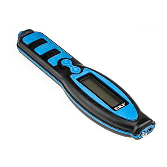
- Page 15 Controls and Functions The SKF Machine Condition Advisor. LCD display Vibration sensor tip Infrared temperature sensor Select button...
- Page 16 Bearing vibration reading (gE) Bearing vibration alarm (none, Alert, or Danger) Bearing vibration alarm class (CL1, CL2, or CL3) Temperature reading (C or F) Measurement status indicator – (run or hold) Battery charge status (75% charged) SKF Machine Condition Advisor User Manual...
- Page 17 How to Set Up your Machine Condition Advisor Prior to using the SKF Machine Condition Advisor, you should fully charge its battery and set up the instrument to best measure your specific machinery. In this section, we describe how to: •...
- Page 18 - or damage to the device. • Charge the device’s battery only with the recommended SKF battery charger. • DO NOT immerse the device in water or other liquids.
- Page 19 • Do not operate the charger with damaged cord or plug. • Do not disassemble the charger; return it to an authorized SKF service center for repair. Disconnect the charger from the outlet prior to • cleaning. • Do not operate the charger if it is damaged in any way.
- Page 20 Machine Condition Advisor in compliance with the IP54 rating. The battery must be replaced at the factory. For battery replacement, contact your local SKF Sales office, or go to http://www.skf.com/cm.repair. SKF Machine Condition Advisor User Manual...
- Page 21 25% of remaining battery life). If temperature readings are not required, the infrared temperature sensor may be disabled to extend battery life. Reference the following How to Make Selections in Setup Mode section for details. SKF Machine Condition Advisor User Manual...
- Page 22 • From the measurement display, press and hold the Browse button (approx. 1 sec) to enter Setup Mode. The Setup Mode menu appears showing the first two menu options. In all Setup Mode menus: SKF Machine Condition Advisor User Manual...
- Page 23 Portuguese, or Swedish System Units English (IPS) or Metric (mm/s) Alarm Velocity Group 1 and 3 (G1&3) or 2 and 4 (G2&4) Foundation (R)igid or (F)lexible Enveloped Acceleration Class CL1 or CL2 or CL3 SKF Machine Condition Advisor User Manual...
- Page 24 Groups 1&3 The ISO standard Group 1 and 3 classifications define the following type of machinery: Large machinery and electrical machines with a • shaft height greater than 315 mm. SKF Machine Condition Advisor User Manual...
- Page 25 Rigid (default) or Flexible foundations. In Setup Mode, select the Foundation option • that describes the mounting type for machinery you’re measuring (Rigid or Flexible). SKF Machine Condition Advisor User Manual...
- Page 26 300 mm and a shaft speed between 500 RPM and 1800 RPM. Bearings with a bearing bore diameter between 20 mm and 150 mm and a shaft speed from 1800 RPM to 3600 RPM. SKF Machine Condition Advisor User Manual...
- Page 27 Vibration sensor tip Infrared temperature sensor Select button Browse button AC power / external sensor connector The SKF Machine Condition Advisor is very simple to use. General steps for use are: • Turn the instrument on. • Place the sensor tip (or a connected external sensor with magnetic tip) against the machine you’re measuring and...
- Page 28 Place the Sensor Tip against the Machine • Press the pen’s sensor tip against your measurement POINT on the machine. For optimal sensor placement, reference the Sensor Placement Techniques section later in this manual. SKF Machine Condition Advisor User Manual...
- Page 29 Measurement results freeze, HOLD appears on the display, and alarm indicators appear for the overall vibration and bearing vibration measurements if their measurement results exceed limits for the specified machinery classifications. SKF Machine Condition Advisor User Manual...
- Page 30 (i.e., bearing fault vibration) than do probe tip sensors. Thus, use the external magnetic mounted sensor to facilitate earlier detection of bearing problems vs. the MCA’s internal sensor. SKF Machine Condition Advisor User Manual...
- Page 31 • On the MCA’s connector, locate the small notch into which the cable connector’s keyway fits. Note that the notch is aligned with the MCA case’s seam. SKF Machine Condition Advisor User Manual...
- Page 32 • Place the sensor’s magnet on your machine measurement POINT. WARNING! Do not allow the external sensor’s cable to become tangled in rotating machinery components. Serious damage or injury may occur. SKF Machine Condition Advisor User Manual...
- Page 33 Perform the remaining measurement steps as previously described. ISO 10816-3 Severity Chart The Machine Condition Advisor compares your overall velocity vibration readings to limits established by ISO 10816-3 guidelines. The following severity chart is provided for your reference. SKF Machine Condition Advisor User Manual...
- Page 34 Danger alarm. Enveloped Acceleration Severity Chart Bearing vibration readings are automatically compared to limits established by SKF based upon years of statistical analysis of existing databases. The following severity chart is provided for your reference. SKF Machine Condition Advisor...
- Page 35 Sensor Position - If possible, choose a flat surface in the bearing’s load zone to press the sensor tip against. Measurements should be taken at the same precise SKF Machine Condition Advisor User Manual...
- Page 36 POINT with permanent ink, machine a shallow conical hole with a drill point, or use SKF’s adhesive measurement disks. Acceleration enveloping measurements (bearing vibration measurements) are especially sensitive to sensor location.
- Page 37 With overall velocity vibration measurements, interpretation of the cause of excess vibration can relate to probe position when taking the measurement; either in the horizontal, vertical, or axial planes. SKF Machine Condition Advisor User Manual...
- Page 38 Infrared Temperature Measurement Guidelines To perform accurate non-contact infrared temperature measurements, consider the following guidelines: Infrared Sensor Cleanliness SKF Machine Condition Advisor User Manual...
- Page 39 0.95. The MCA’s emissivity is set to 0.95 to address most surfaces. Specifications Vibration Pickup: Piezoelectric acceleration sensor Velocity Range: 0.7 to 65.00 mm/s SKF Machine Condition Advisor User Manual...
- Page 40 -20° C to +45° C Range: -4° F to +113° F More than one month but less than six months -20° C to +35° C -4° F to +95° F Humidity: 95% RH non-condensing SKF Machine Condition Advisor User Manual...
- Page 41 Input: 90 to 264 V AC, 47 to 60 Hz Output: 5 V DC regulated Dimensions: width 1.85” (4.7 cm) length 7.9” (20 cm) thickness 1” (2.54 cm) Weight: 125 gms (4.4 oz)) SKF Machine Condition Advisor User Manual...
Need help?
Do you have a question about the CMAS100-SL and is the answer not in the manual?
Questions and answers