METER TEROS 12 Manual
Hide thumbs
Also See for TEROS 12:
- Quick start (3 pages) ,
- Integrator manual (13 pages) ,
- Manual (30 pages)
Table of Contents
Advertisement
Advertisement
Table of Contents

Related Manuals for METER TEROS 12


Summary of Contents for METER TEROS 12
- Page 1 TEROS 12...
-
Page 2: Table Of Contents
1. Introduction ....................1 2. Operation ....................2 2.1 Installation ....................2 2.2 Connecting ....................7 2.2.1 Connect to METER Data Logger ............7 2.2.2 Connect to a Non-METER Logger ............8 2.3 Communication ..................9 3. System ....................... 10 3.1 Specifications ..................10 3.2 Components .....................13 3.3 Theory ......................14... - Page 3 TEROS 12 4.4 Customer Support ..................20 4.5 Terms and Conditions ................21 References ....................22 Index ......................... 23...
-
Page 5: Introduction
Thank you for choosing the TEROS 12 Soil Moisture and Electrical Conductivity (EC) and Temperature sensor. The TEROS 12 sensor is designed to be installed in mineral soils, many types of growing media, and other porous materials. This manual guides the customer through the sensor features and describes how to use the sensor successfully. -
Page 6: Operation
OPERATION 2. OPERATION Please read all instructions before operating the TEROS 12 to ensure it performs to its full potential. SAFETY PRECAUTIONS METER sensors are built to the highest standards. Misuse, improper protection, or improper installation may damage the sensor and possibly void the manufacturer’s warranty. Before integrating the TEROS 12 into a system, follow the recommended installation instructions and have the proper protections in place to safeguard sensors from damage. - Page 7 Create Hole Avoid interferring objects. If the TEROS 12 is installed near large metal objects they can affect the sensor function and distort readings. Avoid large objects like roots or rocks that could potentially bend the needles.
- Page 8 Use ZENTRA Utility software (Section 2.2) to configure desired measurement intervals and verify proper sensor identification by the logger. Click SCAN in ZENTRA Utility to verify the TEROS 12 is active and providing reasonable readings based on soild conditions. Verify that these readings are reasonable based on soil conditions.
- Page 9 Securing excess cable Table 2 contains brief descriptions for typical installation methods. Each has its own advantages and disadvantages. For more information about which installation method is best for specific applications, please see the TEROS 12 Installation Guide or contact Customer Support.
- Page 10 The Borehole Installation Tool is then used to install the sensors in the sidewall of the borehole. NOTE: The borehole method requires specialized installation tool available from METER if installing at depths greater than 50 cm. Trench Advantage Disadvantage The trench installation method is...
-
Page 11: Connecting
TEROS 12. Set the measurement interval. ZENTRA, EM60, or Em50 data loggers measure the TEROS 12 every minute and return the minute-average data across the chosen measurement interval. TEROS 12 data can be downloaded from these loggers using either ZENTRA Utility (desktop and mobile application) -
Page 12: Connect To A Non-Meter Logger
Figure 3 Wiring diagram NOTE: The acceptable range of excitation voltages is from 4 to 15 VDC. To read TEROS 12 sensors with Campbell Scientific, Inc. data loggers, power the sensors from a switched 12 V port or a 12 V port if using a multiplexer. -
Page 13: Communication
TEROS 12 If the TEROS 12 cable has a standard 3.5-mm stereo plug connector and will be connected to a non-METER data logger, please use one of the following two options. Option 1 Clip off the 3.5-mm stereo plug connector on the sensor cable. -
Page 14: System
SYSTEM 3. SYSTEM This section reviews the components and functionality of the TEROS 12 sensor. 3.1 SPECIFICATIONS MEASUREMENT SPECIFICATIONS Volumetric Water Content (VWC) Range Mineral soil calibration 0.00–0.70 m Soilless media 0.0–1.0 m calibration Apparent dielectric 1 (air) to 80 (water) permittivity (ε... - Page 15 TEROS 12 Output DDI serial or SDI-12 communications protocol Data Logger Compatibility Any data acquisition system capable of 4.0- to 15-VDC power and serial or SDI-12 communication PHYSICAL SPECIFICATIONS Dimensions Length 9.4 cm (3.70 in) Width 2.4 cm (0.95 in) Height 7.5 cm (2.95 in)
- Page 16 SYSTEM Digital Input Voltage (logic low) Minimum –0.3 V Typical 0.0 V Maximum 0.8 V Power Line Slew Rate Minimum 1.0 V/ms Typical Maximum Current Drain (during 25-ms measurement) Minimum 3.0 mA Typical 3.6 mA Maximum 16.0 mA Current Drain (while asleep) Minimum Typical 0.03 mA...
-
Page 17: Components
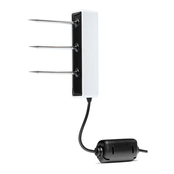
EN61326-1:2013 and EN55022/CISPR 22 3.2 COMPONENTS The TEROS 12 sensor measures soil moisture, temperature, and EC of soil using stainless steel needles (Figure 4). TEROS 12 sensors measure soil moisture between Needle 1 and Needle 2 and EC between Needle 2 and Needle 3. Temperature is measured with an embedded thermistor in Needle 2. -
Page 18: Theory
Figure 5 VWC volume of influence NOTE: The TEROS 12 provides instantaneous or near-instantaneous measurements; however, because of the sensitivity of the measurement of the sensor head, the TEROS 12 is not well suited for spot measurements of VWC. 3.3 THEORY The following sections explain the theory of VWC, temperature, and EC measured by TEROS 12. -
Page 19: Temperature
TEROS 12 3.3.2 TEMPERATURE The TEROS 12 uses a thermistor in the center needle to take temperature readings. This is more important for measurements near the surface where temperature changes are faster. The TEROS 12 sensor output temperature is in degrees Celsius unless otherwise stated in the data logger program, such as in preferences in the ZENTRA software. -
Page 20: Pore Water Versus Saturation Extract Ec
(unitless), is the bulk EC (dS/m) measured directly by the TEROS 12, is the real portion of the dielectric permittivity of the bulk soil (unitless), and ... - Page 21 TEROS 12 Saturation extract EC is the EC of pore water removed from a saturated paste. Saturation extract EC can be measured directly if distilled water is used to wet the soil until the soil saturates. The soil is then placed on filter paper in a vacuum funnel and suction is applied.
-
Page 22: Service
METER or third-party data logger. The TEROS 12 is not sensitive to variation in soil texture and EC because it runs at a high measurement frequency. Therefore, its generic calibration equation should result in reasonable absolute accuracy;... -
Page 23: Apparent Dielectric Permittivity
NOTE: Do not touch the needles with an ungloved hand or bring them in contact with any source of oil or other nonconducting residue. 4.3 TROUBLESHOOTING Table 3 Troubleshooting the TEROS 12 Problem Possible Solution Check power to the sensor. - Page 24 Phone: +1.509.332.5600 Fax: +1.509.332.5158 Website: metergroup.com If contacting METER by email, please include the following information: Name Email address Address Instrument serial number Phone Description of the problem NOTE: For TEROS 12 senosrs purchased through a distributor, please contact the distributor directly for assistance.
- Page 25 TEROS 12 4.5 TERMS AND CONDITIONS By using METER instruments and documentation, you agree to abide by the METER Group, Inc. USA Terms and Conditions. Please refer to www.metergroup.com/company/meter-group- inc-usa-terms-conditions for details.
- Page 26 REFERENCES REFERENCES Hilhorst MA. 2000. A pore water conductivity sensor. Soil Science Society of America Journal 64:6 1922–1925. Topp GC, David JL, and Annan AP. 1980. Electromagnetic determination of soil water content: Measurement in coaxial transmission lines. Water Resources Research 16(3): 574–582.
- Page 27 See cleaning the sensors connector types 11 ferrite core 14 needles 11, 13 references 22 thermistor 13 configuration See data loggers, connect to METER logger safety 2 customer support 20 soil moisture 13 specifications 10–13 data logger compatibility 11 data loggers 7–8, 11...
- Page 28 INDEX temperature theory 15 terms and conditions 21–22 theory 14–17 electrical conductivity 15–17 See also electrical conductivity temperature 15 volumetric water content 14 See theory, volumetric water content troubleshooting 19–20 volumetric water content specifications 10 theory 14...
- Page 29 18226-01 4.26.2018 METER Group, Inc. USA 2365 NE Hopkins Court Pullman, WA 99163 T: +1.509-332-5600 F: +1.509.332.5158 E: info@metergroup.com W: www.metergroup.com © 2018 All Rights Reserved. Printed in USA.
Need help?
Do you have a question about the TEROS 12 and is the answer not in the manual?
Questions and answers