
Related Manuals for Huawei TP482000B Series


Summary of Contents for Huawei TP482000B Series
- Page 1 TP482000B V300R002C03 Telecom Power (TP482000B-N20B1, TP482000B-N20B2, TP481200B-N20B1, and TP481200B-N20B2) User Manual Issue Date 2020-04-10 HUAWEI TECHNOLOGIES CO., LTD.
- Page 2 Notice The purchased products, services and features are stipulated by the contract made between Huawei and the customer. All or part of the products, services and features described in this document may not be within the purchase scope or the usage scope. Unless otherwise specified in the contract, all statements, information, and recommendations in this document are provided "AS IS"...
-
Page 3: About This Document
NOTICE is used to address practices not related to personal injury. Supplements the important information in the main text. NOTE is used to address information not related to personal injury, equipment damage, and environment deterioration. Issue 07 (2020-04-10) Copyright © Huawei Technologies Co., Ltd. - Page 4 Optimized the descriptions. Issue 03 (2017-01-03) Modified 5.2.1 SMU05A. Issue 02 (2016-05-31) Modified Figure 4-3, Figure 4-4 C Engineering Design Drawings. Issue 01 (2016-01-13) This issue is the first official release. Issue 07 (2020-04-10) Copyright © Huawei Technologies Co., Ltd.
-
Page 5: Table Of Contents
5.2.2 Power Distribution Monitoring Unit ........................41 6 Routine Maintenance ......................48 6.1 Cabinet .................................48 6.2 AC and DC Power Distribution ..........................48 6.3 Rectifier ................................49 6.4 SMU ..................................50 6.5 Parameters on the SMU ............................51 Issue 07 (2020-04-10) Copyright © Huawei Technologies Co., Ltd. - Page 6 8.5 Disasters................................81 A Technical Specifications ....................... 82 B Electrical Conceptual Diagram .................... 87 C Engineering Design Drawings .................... 93 D Maintenance Record Forms ....................95 E Acronyms and Abbreviations .................... 100 Issue 07 (2020-04-10) Copyright © Huawei Technologies Co., Ltd.
-
Page 7: Safety Precautions
The "NOTICE", "CAUTION", "WARNING", and "DANGER" statements in this document do not cover all the safety instructions. They are only supplements to the safety instructions. Huawei will not be liable for any consequence caused by the violation of general safety requirements or design, production, and usage safety standards. - Page 8 Installation personnel mark tightened bolts in blue. Quality inspection personnel confirm if the bolts are tightened and then mark them in red. (The marks should cross the edges of the bolts, as shown in the following figure.) Issue 07 (2020-04-10) Copyright © Huawei Technologies Co., Ltd.
- Page 9 To avoid electric shock, do not connect safety extra-low voltage (SELV) circuits to telecommunication network voltage (TNV) circuits. Do not power on the equipment before it is installed or confirmed by professionals. Issue 07 (2020-04-10) Copyright © Huawei Technologies Co., Ltd.
- Page 10 2. If there are multiple output ports, use the symbol near the output ports. Connect cables according to the rated power output and configuration parameter information in the instruction. 3. If there are multiple slots, use the symbol near the slot Issue 07 (2020-04-10) Copyright © Huawei Technologies Co., Ltd.
-
Page 11: Personnel Requirements
1.2 Personnel Requirements Personnel who plan to install or maintain Huawei equipment must receive thorough training, understand all necessary safety precautions, and be able to correctly perform all operations. ... - Page 12 When holding a board, hold its edge without touching any components. Do not touch the components with your bare hands. Package boards with ESD packaging materials before storing or transporting them. Issue 07 (2020-04-10) Copyright © Huawei Technologies Co., Ltd.
-
Page 13: Installation Environment Requirements
Do not mount it on an insecure moveable object or metal object with sharp edges. Make sure that the hooks will not slide off. Issue 07 (2020-04-10) Copyright © Huawei Technologies Co., Ltd. -
Page 14: Mechanical Safety
Before hoisting objects, ensure that hoisting tools are firmly secured onto a load-bearing object or wall. Ensure that the angle formed by two hoisting cables is no more than 90 degrees, as shown in the following figure. Issue 07 (2020-04-10) Copyright © Huawei Technologies Co., Ltd. - Page 15 75 degrees, as shown in the following figure. An angle rule can be used to measure the angle. When climbing a ladder, take the following precautions to reduce risks and ensure safety: Issue 07 (2020-04-10) Copyright © Huawei Technologies Co., Ltd.
- Page 16 Moving Heavy Objects Be cautious to avoid injury when moving heavy objects. When moving the equipment by hand, wear protective gloves to prevent injuries. Issue 07 (2020-04-10) Copyright © Huawei Technologies Co., Ltd.
-
Page 17: Battery Safety
Dispose of waste batteries in accordance with local laws and regulations. Do not dispose of batteries as household waste. If a battery is disposed of improperly, it may explode. Issue 07 (2020-04-10) Copyright © Huawei Technologies Co., Ltd. - Page 18 If permitted, disconnect the batteries in use before performing any other operations. To avoid battery short-circuit, do not maintain batteries with power on. Flammable Gas Issue 07 (2020-04-10) Copyright © Huawei Technologies Co., Ltd.
- Page 19 When the ambient temperature is lower than the lower limit of the operating temperature (charge is forbidden at 0° C), do not charge the battery. Otherwise, a short circuit would occur inside the battery. Do not throw a lithium battery in fire. Issue 07 (2020-04-10) Copyright © Huawei Technologies Co., Ltd.
- Page 20 TP482000B V300R002C03 Telecom Power (TP482000B-N20B1, TP482000B-N20B2, TP481200B-N20B1, and TP481200B-N20B2) User Manual 1 Safety Precautions When maintenance is complete, return the waste lithium battery to the maintenance office. Issue 07 (2020-04-10) Copyright © Huawei Technologies Co., Ltd.
-
Page 21: Overview
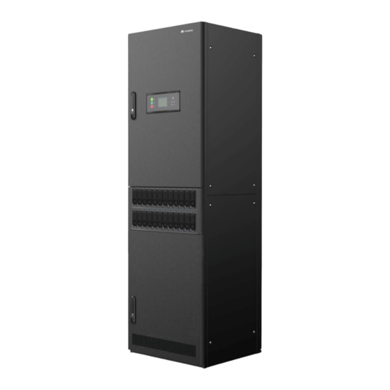
Overview 2.1 Introduction The TP482000B is Huawei's fourth-generation high-performance indoor telecom power system. The system supplies reliable –48 V DC power to equipment in central equipment rooms. The TP482000B is available in four different models of combined cabinets, each of which contains an AC power distribution unit (PDU), a DC PDU, rectifiers, and a site monitoring unit (SMU). -
Page 22: Features
The liquid crystal display (LCD) and five buttons on the SMU allow users to quickly view system information. Fault isolation All rectifiers support fault isolation. If one rectifier is faulty, the other rectifiers still work properly. Easy maintenance Issue 07 (2020-04-10) Copyright © Huawei Technologies Co., Ltd. - Page 23 High reliability − The power system has a service life of 10 years, mean time between failures (MTBF) of 500,000 hours, and a failure rate of 2000 FITs. Issue 07 (2020-04-10) Copyright © Huawei Technologies Co., Ltd.
-
Page 24: Product Configurations
Two 2000 A/25 mV shunts monitoring Total load current One 2000 A/25 mV shunt monitoring DC power indicator One DC power indicator (green) System alarm indicator One system alarm indicator (red) Issue 07 (2020-04-10) Copyright © Huawei Technologies Co., Ltd. - Page 25 One system alarm indicator (red) DC surge protection DC SPD (10 kA in differential mode, 20 kA in common mode, 8/20 µ s) Monitoring unit SMU05A Signal monitoring Power distribution monitoring unit Issue 07 (2020-04-10) Copyright © Huawei Technologies Co., Ltd.
- Page 26 TP481200B-N20B2 Flexible Configurations Configurations AC input system 120/208 V AC (three-phase three-wire or three-phase four-wire), compatible with 220/380 V AC three-phase four-wire AC input circuit One 3-pole 300 A circuit breaker Issue 07 (2020-04-10) Copyright © Huawei Technologies Co., Ltd.
-
Page 27: Typical Multi-Cabinet Configurations
TP482000B-N20B1 or TP482000B-N20B2. Table lists the typical configurations of TP481200B-N20B1 or TP481200B-N20B2. Table 3-5 TP482000B-N20B1 or TP482000B-N20B2 typical configurations System Capacity (kW) Combined cabinet TP482000B-N20B1 or TP482000B-N20B2 (PCS) Issue 07 (2020-04-10) Copyright © Huawei Technologies Co., Ltd. -
Page 28: Typical Multi-Cabinet Layout
TP483000D AC cabinets and DC cabinets can be connected to TP482000B cabinets. 3.3 Typical Multi-cabinet Layout Figure 3-1 360 kW/720 kW system Only combined cabinets of the same model can be connected together, up to a maximum of five cabinets. Issue 07 (2020-04-10) Copyright © Huawei Technologies Co., Ltd. -
Page 29: Cabinet Configurations
4 Cabinet Configurations Cabinet Configurations 4.1 Combined Cabinet TP482000B-N20B1 Figure 4-1 Table 4-1 illustrate the TP482000B-N20B1 configurations. Load routes can be flexibly configured based on site requirements. Figure 4-1 TP482000B-N20B1 configurations Issue 07 (2020-04-10) Copyright © Huawei Technologies Co., Ltd. - Page 30 Two 4-pole 32 A SPD circuit breakers SMU05A 1 PCS Power distribution monitoring 1 PCS unit TP482000B-N20B2 Figure 4-2 Table 4-2 illustrate the TP482000B-N20B2 configurations. Load routes can be flexibly configured based on site requirements. Issue 07 (2020-04-10) Copyright © Huawei Technologies Co., Ltd.
- Page 31 AC SPD and SPD circuit Two 20 kA/40 kA SPDs breaker Two 4-pole 32 A SPD circuit breakers SMU05A 1 PCS Power distribution monitoring 1 PCS unit Issue 07 (2020-04-10) Copyright © Huawei Technologies Co., Ltd.
- Page 32 Rectifier circuit breaker Single layer: twenty-four 1-pole 32 A circuit breakers AC SPD and SPD circuit One 20 kA/40 kA SPD breaker One 4-pole 32 A SPD circuit breaker Issue 07 (2020-04-10) Copyright © Huawei Technologies Co., Ltd.
- Page 33 1 PCS Power distribution 1 PCS monitoring unit TP481200B-N20B2 Figure 4-4 Table 4-4 illustrate the TP481200B-N20B2 configurations. Load routes can be flexibly configured based on site requirements. Figure 4-4 TP481200B-N20B2 configurations Issue 07 (2020-04-10) Copyright © Huawei Technologies Co., Ltd.
-
Page 34: Ac Cabinet
4.2 AC Cabinet Configure the AC input, AC output, and emergency lighting output for the TP483000D AC cabinet based on site requirements, as illustrated in Figure 4-5 Table 4-5. Issue 07 (2020-04-10) Copyright © Huawei Technologies Co., Ltd. - Page 35 Optional configuration lighting output TPA38631B-N20B1 AC SPD and AC TPA38401B-N20B1 One 20 kA/40 kA SPD Typical configuration surge protection One 4-pole 32 A surge TPA38631B-N20B1 circuit breaker protection circuit breaker Issue 07 (2020-04-10) Copyright © Huawei Technologies Co., Ltd.
-
Page 36: Dc Cabinet
Configure the battery route and load route for the TP483000D DC cabinet based on site requirements. For battery route configurations, see Figure 4-6 Table 4-6. For load route configurations, see Figure 4-7 Table 4-7. Issue 07 (2020-04-10) Copyright © Huawei Technologies Co., Ltd. - Page 37 TPD48302B-N20B1 parallel Contactor TPD48202B-N20B1 3000 A Optional configuration TPD48302B-N20B1 Battery fuse TPD48202B-N20B1 Six NT3 fuses Optional configuration Four NT4 fuses TPD48302B-N20B1 Copper RTN expansion TPD48202B-N20B1 Optional configuration TPD48302B-N20B1 Issue 07 (2020-04-10) Copyright © Huawei Technologies Co., Ltd.
- Page 38 Single layer: eight NT1 fuses maximum of two layers of fuses or circuit breakers. Load fuse TPD48202B-N20B1 Single layer: fourteen NT00 fuses TPD48302B-N20B1 Load circuit TPD48202B-N20B1 Single layer: thirty-eight 1-pole Issue 07 (2020-04-10) Copyright © Huawei Technologies Co., Ltd.
- Page 39 Specifications Remarks breaker TPD48302B-N20B1 6–63 A MCBs Single layer: twenty-five 1-pole 63–125 A MCBs The capacity of a single layer of load fuses or circuit breakers does not exceed 1000 A. Issue 07 (2020-04-10) Copyright © Huawei Technologies Co., Ltd.
-
Page 40: Components
(5) Handle Table 5-1 Indicator description Indicator Color Status Description Power indicator Green Steady on The rectifier has an AC input. The rectifier has no AC input. The rectifier is faulty. Issue 07 (2020-04-10) Copyright © Huawei Technologies Co., Ltd. - Page 41 0.5 Hz external device is interrupted. Fault indicator The rectifier is normal. Steady on The rectifier locks out due to output overvoltage. The rectifier has no output due to an internal fault. Issue 07 (2020-04-10) Copyright © Huawei Technologies Co., Ltd.
-
Page 42: Monitoring Unit
Enters the standby screen from any screen or enters the active alarm screen from the standby screen. If the Info button is blinking at 0.5 Hz, the SMU05A is running properly and communicating with the host properly. Issue 07 (2020-04-10) Copyright © Huawei Technologies Co., Ltd. - Page 43 To increase or decrease a parameter value quickly, hold down The SMU05A uses a 3.5-inch LCD, which displays up to seven rows of large-font menu items on each screen. Ports Figure 5-3 SMU05A ports Issue 07 (2020-04-10) Copyright © Huawei Technologies Co., Ltd.
- Page 44 Four dry contact inputs. Eight dry contact outputs. Figure 5-4 RS232 port pins Table 5-4 RS232 port pin definition Signal Description Receive Transmit Ground 1, 4, 6, 7, 8, and 9 Issue 07 (2020-04-10) Copyright © Huawei Technologies Co., Ltd.
- Page 45 Table 5-7 COM port pin definition Signal Description RS485+ RS485 data+ RS485- RS485 data- RS485+ RS485 data+ RS485- RS485 data- CAN_H CAN high level signal CAN_L CAN low level signal 3 and 6 Issue 07 (2020-04-10) Copyright © Huawei Technologies Co., Ltd.
- Page 46 Dry contact input 4 Dry contact ALM1 Dry contact output 1 output ALM2 Dry contact output 2 ports ALM3 Dry contact output 3 ALM4 Dry contact output 4 ALM5 Dry contact output 5 Issue 07 (2020-04-10) Copyright © Huawei Technologies Co., Ltd.
-
Page 47: Power Distribution Monitoring Unit
(3) Indicator (4) Main control board 5.2.2 Power Distribution Monitoring Unit The power distribution monitoring unit is used to monitor AC or DC power distribution. It provides detection, alarm, and communication functions. Issue 07 (2020-04-10) Copyright © Huawei Technologies Co., Ltd. - Page 48 Figure 5-8 Panel of the power distribution monitoring unit (DC cabinet) (1) Power indicator (2) Alarm indicator (3) LCD (4) Up button (5) Down button (6) OK button (7) ESC button (8) Info button Issue 07 (2020-04-10) Copyright © Huawei Technologies Co., Ltd.
- Page 49 (3) CAN ports (4) PELU port (5) Ambient temperature (6) Battery temperature sensor port AMBI_TEMP sensor port BAT_TEMP1 (reserved) (7) Battery temperature (8) Battery temperature sensor port BAT_TEMP2 sensor port BAT_TEMP3 (reserved) (reserved) Issue 07 (2020-04-10) Copyright © Huawei Technologies Co., Ltd.
- Page 50 Communications Protocol Connects inter-cabinet CAN2.0 communications cables. RS485/RS232 Connects to a host or NMS. YDN protocol or Huawei master/slave protocol Connects to an intelligent Modbus protocol communications device. PELU Cabinet e-label port. Issue 07 (2020-04-10) Copyright © Huawei Technologies Co., Ltd.
- Page 51 Transmits data over RS232. 4, 5, 8 Table 5-15 COM port pin definitions Signal Description RS485+ RS485 data + (A) RS485 data – (B) RS485- 3, 4, 5, 6, 7, 8 Issue 07 (2020-04-10) Copyright © Huawei Technologies Co., Ltd.
- Page 52 The figure shows the interior structure with the cover removed. Figure 5-12 Interior of the power distribution monitoring unit (AC or DC cabinet) (1) Button board (2) LCD (3) Signal sampling board (4) Signal transfer board (5) Indicator Issue 07 (2020-04-10) Copyright © Huawei Technologies Co., Ltd.
- Page 53 TP482000B V300R002C03 Telecom Power (TP482000B-N20B1, TP482000B-N20B2, TP481200B-N20B1, and TP481200B-N20B2) User Manual 5 Components Figure 5-13 Interior of the power distribution monitoring unit (combined cabinet) (1) Signal transfer board (2) Signal sampling board Issue 07 (2020-04-10) Copyright © Huawei Technologies Co., Ltd.
-
Page 54: Routine Maintenance
OFF: A voltage surge or it is damaged, replace it status. lightning strike has occurred. 2. Turn on the circuit breaker if ON: The SPD is normal. the SPD is intact. Issue 07 (2020-04-10) Copyright © Huawei Technologies Co., Ltd. -
Page 55: Rectifier
2. Rectify faults in the indoor to ambient overtemperature. temperature control system. The rectifier has shut down 3. Check the AC input voltage. as a protective measure Issue 07 (2020-04-10) Copyright © Huawei Technologies Co., Ltd. -
Page 56: Smu
Check that the SMU can The communications cable communications cable is communicate with the NMS. is loose. securely connected. Networking parameters are 2. Check that networking not correctly set. parameter settings are correct. Issue 07 (2020-04-10) Copyright © Huawei Technologies Co., Ltd. -
Page 57: Parameters On The Smu
Cables are installed too close to Install cables at least 20 mm 20 mm away from DC negative DC negative busbars, fuses, and away from DC negative busbars, busbars, fuses, and shunts. shunts. fuses, and shunts. Issue 07 (2020-04-10) Copyright © Huawei Technologies Co., Ltd. - Page 58 Check whether power cables use Cables do not use stand Replace with standard terminals. standard terminals. terminals. Check whether cable insulation is Cable insulation is damaged. Reinsulate the cables with damaged. insulation tape. Issue 07 (2020-04-10) Copyright © Huawei Technologies Co., Ltd.
-
Page 59: Parts Replacement
Figure 7-1 Removing the rectifier Step 4 Push the locking latch on the new rectifier upwards, and pull out the handle. Step 5 Place the new rectifier in the appropriate slot. Issue 07 (2020-04-10) Copyright © Huawei Technologies Co., Ltd. -
Page 60: Replacing The Smu05A
Figure 7-2 Installing a new rectifier Step 7 Remove the protective gloves. ----End Follow-up Procedure Pack the removed component and have it sent to the local Huawei warehouse. 7.2 Replacing the SMU05A 7.2.1 Replacing the Main Control Board Prerequisites ... - Page 61 Record the positions of cables connected to the main control board, and disconnect the power cable from the J12 port on the main control board. Disconnect communications cables and signal cables from the main control board. Unscrew and remove the main control board. Issue 07 (2020-04-10) Copyright © Huawei Technologies Co., Ltd.
- Page 62 If a combined cabinet is in required. any other position, set toggle switch 4 to Off. Issue 07 (2020-04-10) Copyright © Huawei Technologies Co., Ltd.
- Page 63 Table 7-2 Setting the SMU IP address Main Menu Second-Level Third-Level Menu Default Value Setting Menu Setting Wizard Network Parameters IP 192.168.0.10 Apply to the network administrator for an address. Subnet Mask 255.255.255.0 Apply to the network Issue 07 (2020-04-10) Copyright © Huawei Technologies Co., Ltd.
-
Page 64: Replacing The Lcd
Step 1 Connect the ground cable for the ESD wrist strap, and put on the ESD wrist strap and ESD gloves. Step 2 Record the positions of cables connected to RJ45 ports on the SMU, and disconnect the cables from the ports. Step 3 Unscrew and remove the SMU cover. Issue 07 (2020-04-10) Copyright © Huawei Technologies Co., Ltd. - Page 65 Place the new LCD in position and tighten the screws. Connect the LCD flat cable to the main control board. Reconnect the power cable to the J12 port on the main control board. Issue 07 (2020-04-10) Copyright © Huawei Technologies Co., Ltd.
-
Page 66: Replacing The Button Board
Step 1 Connect the ground cable for the ESD wrist strap, and put on the ESD wrist strap and ESD gloves. Step 2 Record the positions of cables connected to RJ45 ports on the SMU, and disconnect the cables from the ports. Step 3 Remove the cover from the SMU. Issue 07 (2020-04-10) Copyright © Huawei Technologies Co., Ltd. - Page 67 Step 5 Unscrew and remove the button board, as shown in Figure 7-11. Figure 7-11 Removing a button board Step 6 Place the new button board in position and tighten the screws, as shown in Figure 7-12. Issue 07 (2020-04-10) Copyright © Huawei Technologies Co., Ltd.
-
Page 68: Replacing The Power Distribution Monitoring Unit
The new signal sampling board is intact. Context To replace the signal sampling board, you do not need to disconnect the AC input to the power system. Issue 07 (2020-04-10) Copyright © Huawei Technologies Co., Ltd. - Page 69 Record the positions of cables connected to the signal sampling board, and disconnect the power cable from the J98 port on the signal sampling board. Disconnect communications cables and signal cables from the signal sampling board. Unscrew and remove the signal sampling board. Issue 07 (2020-04-10) Copyright © Huawei Technologies Co., Ltd.
- Page 70 7 Parts Replacement Figure 7-14 Removing a signal sampling board Step 5 Record the settings of dual-in-line package (DIP) switch S1 for the signal sampling board, as shown in Figure 7-15. Issue 07 (2020-04-10) Copyright © Huawei Technologies Co., Ltd.
- Page 71 6. no further action is If an combined required. cabinet is in any other position, set toggle switch 6 to Off. Issue 07 (2020-04-10) Copyright © Huawei Technologies Co., Ltd.
- Page 72 Off. Step 6 Set DIP switch S1 for the new signal sampling board based on the recorded information. Step 7 Install the new signal sampling board, as shown in Figure 7-16. Issue 07 (2020-04-10) Copyright © Huawei Technologies Co., Ltd.
-
Page 73: Replacing The Lcd
You have obtained an ESD wrist strap, a pair of ESD gloves, an ESD box or bag, a tool kit, and the cabinet door key. The new LCD is intact. Issue 07 (2020-04-10) Copyright © Huawei Technologies Co., Ltd. - Page 74 Unscrew and remove the LCD. Figure 7-17 Removing an LCD Step 5 Install the new LCD, as shown in Figure 7-18. Place the new LCD in position and tighten the screws. Issue 07 (2020-04-10) Copyright © Huawei Technologies Co., Ltd.
-
Page 75: Replacing The Button Board
You have obtained an ESD wrist strap, a pair of ESD gloves, an ESD box or bag, a tool kit, and the cabinet door key. The new button board is intact. Issue 07 (2020-04-10) Copyright © Huawei Technologies Co., Ltd. - Page 76 Step 8 Place the cover on the power distribution monitoring unit, and tighten the screws. Step 9 Reconnect the cables to the RJ45 ports on the power distribution monitoring unit based on the recorded information. Issue 07 (2020-04-10) Copyright © Huawei Technologies Co., Ltd.
-
Page 77: Replacing The Signal Transfer Board
Step 2 Loosen the screws on the maintenance terminal of the AC transformer in the AC cabinet. After the metal bridgeware slides down to short-circuit the maintenance terminal, tighten the screws, as shown in Figure 7-20. Issue 07 (2020-04-10) Copyright © Huawei Technologies Co., Ltd. - Page 78 Step 5 Unscrew and remove the cover from the signal transfer board, as shown in Figure 7-21. Use an M4 hex key to unscrew the cover of the signal transfer board. Issue 07 (2020-04-10) Copyright © Huawei Technologies Co., Ltd.
- Page 79 Step 6 Remove the signal transfer board, as shown in Figure 7-22. Record the positions of cables connected to the signal transfer board, and disconnect the cables. Unscrew and remove the signal transfer board. Issue 07 (2020-04-10) Copyright © Huawei Technologies Co., Ltd.
-
Page 80: Replacing An Ac Spd
You have obtained an ESD wrist strap, a pair of ESD gloves, an ESD box or bag, a tool kit, and the cabinet door key. The new AC SPD is intact and the indication window is green. Issue 07 (2020-04-10) Copyright © Huawei Technologies Co., Ltd. -
Page 81: Replacing A Circuit Breaker
7.5 Replacing a Circuit Breaker Prerequisites Before replacing an AC circuit breaker, switch off the upstream input circuit breaker. The cabinet door key, insulation tape, and required tools are available. Issue 07 (2020-04-10) Copyright © Huawei Technologies Co., Ltd. - Page 82 Step 9 Switch on the circuit breaker. Figure 7-25 shows how to install the new circuit breaker. Issue 07 (2020-04-10) Copyright © Huawei Technologies Co., Ltd.
-
Page 83: Replacing A Fuse
Fuses are hot-swappable. You do not need to disconnect the AC input to the power system. Procedure Step 1 Loosen the bolts that secure the fuse, as shown in Figure 7-26. Issue 07 (2020-04-10) Copyright © Huawei Technologies Co., Ltd. - Page 84 Hold the fuse extracting unit, align the fuse with the fuse base, and insert the fuse into the fuse base. Press the button on the fuse extracting unit. Move the fuse away from the fuse extracting unit. Issue 07 (2020-04-10) Copyright © Huawei Technologies Co., Ltd.
- Page 85 TP482000B V300R002C03 Telecom Power (TP482000B-N20B1, TP482000B-N20B2, TP481200B-N20B1, and TP481200B-N20B2) User Manual 7 Parts Replacement Figure 7-28 Installing a fuse Step 4 Tighten bolts to secure the fuse. ----End Issue 07 (2020-04-10) Copyright © Huawei Technologies Co., Ltd.
-
Page 86: Emergency Handling
If a DC power distribution unit (PDU) is faulty, take emergency measures as follows: Load short-circuit: Remove the corresponding load fuse. If you need to replace the fuse immediately, check that the fuse can be replaced with the power off. Issue 07 (2020-04-10) Copyright © Huawei Technologies Co., Ltd. -
Page 87: Disasters
Take precautions against disasters that could severely affect communications security, and ensure that suitable countermeasures, personnel, material resources, regulations, and repair procedures are available at the local communications site to handle any emergencies. Issue 07 (2020-04-10) Copyright © Huawei Technologies Co., Ltd. -
Page 88: A Technical Specifications
TP481200B-N20B2: 120/208 V AC (three-phase three-wire or three-phase four-wire), compatible with 220/380 V AC three-phase four-wire Input frequency 50/60 Hz (range: 45–66 Hz) ≥ 0.99 (rated load) Power factor Issue 07 (2020-04-10) Copyright © Huawei Technologies Co., Ltd. - Page 89 Harmonic current EN61000-3-12 Voltage fluctuation and EN61000-3-11 flicker EN61000-4-2 Enclosure port: 6 kV (criterion B) contact discharge; 8 kV (criterion B) air discharge Signal port: 2 kV (criterion R) contact discharge Issue 07 (2020-04-10) Copyright © Huawei Technologies Co., Ltd.
- Page 90 Cooling mode Natural cooling Table A-2 Technical specifications for AC cabinets Category Item Specifications –10° C to +45° C Environment Operating temperature Issue 07 (2020-04-10) Copyright © Huawei Technologies Co., Ltd.
- Page 91 Table A-3 Technical specifications for DC cabinets Category Item Specifications –10° C to +45° C Environment Operating temperature –40° C to +70° C Storage temperature –40° C to +70° C Transport temperature Operating humidity 5%–95% RH (non-condensing) Issue 07 (2020-04-10) Copyright © Huawei Technologies Co., Ltd.
- Page 92 On a concrete floor or ESD floor Cable routing Routed in and out from the top or bottom Maintenance mode Maintained from the front or rear (at least 650 mm away from a wall) Heat dissipation Natural Issue 07 (2020-04-10) Copyright © Huawei Technologies Co., Ltd.
-
Page 93: B Electrical Conceptual Diagram
TP482000B V300R002C03 Telecom Power (TP482000B-N20B1, TP482000B-N20B2, TP481200B-N20B1, and TP481200B-N20B2) User Manual B Electrical Conceptual Diagram Electrical Conceptual Diagram Figure B-1 Electrical conceptual diagram of TP482000B-N20B1 Issue 07 (2020-04-10) Copyright © Huawei Technologies Co., Ltd. - Page 94 TP482000B V300R002C03 Telecom Power (TP482000B-N20B1, TP482000B-N20B2, TP481200B-N20B1, and TP481200B-N20B2) User Manual B Electrical Conceptual Diagram Figure B-2 Electrical conceptual diagram of TP482000B-N20B2 Issue 07 (2020-04-10) Copyright © Huawei Technologies Co., Ltd.
- Page 95 TP482000B V300R002C03 Telecom Power (TP482000B-N20B1, TP482000B-N20B2, TP481200B-N20B1, and TP481200B-N20B2) User Manual B Electrical Conceptual Diagram Figure B-3 Electrical conceptual diagram of TP481200B-N20B1 Issue 07 (2020-04-10) Copyright © Huawei Technologies Co., Ltd.
- Page 96 TP482000B V300R002C03 Telecom Power (TP482000B-N20B1, TP482000B-N20B2, TP481200B-N20B1, and TP481200B-N20B2) User Manual B Electrical Conceptual Diagram Figure B-4 Electrical conceptual diagram of TP481200B-N20B2 Issue 07 (2020-04-10) Copyright © Huawei Technologies Co., Ltd.
- Page 97 TP482000B V300R002C03 Telecom Power (TP482000B-N20B1, TP482000B-N20B2, TP481200B-N20B1, and TP481200B-N20B2) User Manual B Electrical Conceptual Diagram Figure B-5 Electrical conceptual diagram of TP483000D AC Issue 07 (2020-04-10) Copyright © Huawei Technologies Co., Ltd.
- Page 98 TP482000B V300R002C03 Telecom Power (TP482000B-N20B1, TP482000B-N20B2, TP481200B-N20B1, and TP481200B-N20B2) User Manual B Electrical Conceptual Diagram Figure B-6 Electrical conceptual diagram of TP483000D DC Issue 07 (2020-04-10) Copyright © Huawei Technologies Co., Ltd.
-
Page 99: C Engineering Design Drawings
TP482000B V300R002C03 Telecom Power (TP482000B-N20B1, TP482000B-N20B2, TP481200B-N20B1, and TP481200B-N20B2) User Manual C Engineering Design Drawings Engineering Design Drawings Figure C-1 Engineering design drawing for the 1200 A cabinet Issue 07 (2020-04-10) Copyright © Huawei Technologies Co., Ltd. - Page 100 TP482000B V300R002C03 Telecom Power (TP482000B-N20B1, TP482000B-N20B2, TP481200B-N20B1, and TP481200B-N20B2) User Manual C Engineering Design Drawings Figure C-2 Engineering design drawing for the 2400 A cabinet#fig1747175074710 Issue 07 (2020-04-10) Copyright © Huawei Technologies Co., Ltd.
-
Page 101: D Maintenance Record Forms
□ Others________ Table D-3 AC and DC power distribution maintenance records Maintenance Item Result Measure □ Passed □ Replace the SPD. No indicator on the SPD is red. □ Failed □ Others________ Issue 07 (2020-04-10) Copyright © Huawei Technologies Co., Ltd. - Page 102 The DC busbar Busbar temperature: ____° C connections. temperature does not exceed 95° C at the room □ Passed □ Check the load status, temperature. and rectify faults. □ Failed □ Others________ Issue 07 (2020-04-10) Copyright © Huawei Technologies Co., Ltd.
- Page 103 □ No display □ Replace the SMU. □ Others________ □ Passed □ Change the The SMU communication with the NMS is normal. communications cables. □ Failed □ Set network parameters again. □ Others________ Issue 07 (2020-04-10) Copyright © Huawei Technologies Co., Ltd.
- Page 104 □ Failed □ Others________ □ Passed □ Change the cable Cables are at least 20 mm away from negative DC busbars, routing. □ Failed fuses, and shunts. □ Others________ Issue 07 (2020-04-10) Copyright © Huawei Technologies Co., Ltd.
- Page 105 No cable passes behind the air exhaust vents of rectifiers. routing. □ Failed □ Others________ □ Passed □ Use power cables Power cables use standard terminals. with standard terminals. □ Failed □ Others________ Issue 07 (2020-04-10) Copyright © Huawei Technologies Co., Ltd.
-
Page 106: E Acronyms And Abbreviations
Acronyms and Abbreviations automatic transfer switch electromagnetic compatibility electromagnetic susceptibility electrostatic discharge fast Ethernet hypertext transfer protocol secure HTTPS liquid crystal display manual transfer switch site monitoring unit Simple Network Management Protocol SNMP Issue 07 (2020-04-10) Copyright © Huawei Technologies Co., Ltd. - Page 107 TP482000B V300R002C03 Telecom Power (TP482000B-N20B1, TP482000B-N20B2, TP481200B-N20B1, and TP481200B-N20B2) User Manual E Acronyms and Abbreviations surge protection device Issue 07 (2020-04-10) Copyright © Huawei Technologies Co., Ltd.