Advertisement
Quick Links
Advertisement

Related Manuals for Garrard 301


Summary of Contents for Garrard 301
- Page 2 MANUAL for the GARRARD MODEL 301 TRANSCRIPTION MOTOR arrard ngineering and anufacturing ompany imited windon ngland...
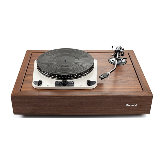
- Page 3 Introduction S the owner of this Garrard Model 301 Transcription Motor you have a unit whose perfor mance is supreme in its class and this manual has been prepared to enable you to enjoy and maintain the high performance which this motor can achieve.
- Page 4 FIRST EDITION 1954 SECOND EDITION 1956 THIRD EDITION 1957 FOURTH EDITION 1958 FIFTH EDITION 1959 SIXTH EDITION 1961...
-
Page 5: Table Of Contents
Index page DESCRIPTION........7 OPERATING INSTRUCTIONS TECHNICAL DETAILS - - 11 MAINTENANCE - - 12 INSTALLATION INSTRUCTIONS - 13 SERVICE ADJUSTMENTS - - 17 SPARES LIST........19 This Manual is supplied with Motor number... - Page 6 THE GARRARD MODEL 301 TRANSCRIPTION MOTOR...
-
Page 7: Description
Description HE Garrard Model 301 Transcription Motor is the culmination of over 40 years’ experience in the design and manufacture of high quality gramophone equipment, and this motor has been designed to provide the professional user and quality enthusiast with a unit supreme in its class. -
Page 8: Operating Instructions
Operation To operate the Garrard Model 301 Transcription Motor proceed as follows:— (1) Move speed range knob to desired speed Diagram 1 (2) Place record on turntable Diagram 2... - Page 9 (3) Switch on Diagram 3 To set speed place a record on the turntable and then place the stroboscope on the record. Start motor. Place pickup on record and turn the speed adjusting knob until the ring of lines applying to that speed for which you are setting appear to remain stationary when illuminated under an appropriate A.C.
- Page 10 Diagram 4 To protect the intermediate wheel from damage the speed change knob is interlocked with the on-off knob. To change the speed range the motor must be switched off by means of the on-off knob. The turntable must not be held stationary with the motor switched on and the on-off switch on the motor should always be used for stopping.
-
Page 11: Technical Details
Technical Details - Diecast Aluminium 12" diameter Turntable machined all over and accurately balanced. Weight 6 lbs. Fitted with rubber mat. A three speed stroboscopically engraved turntable is available at extra cost. - Diecast Aluminium. Unit Plate - Shaded pole induction in heavy cast Motor casing suspended on six tensioned springs. -
Page 12: Maintenance
Maintenance The Turntable Spindle, motor and intermediate wheel bearings being of the oil retaining type rarely need lubricating. When however the need for oil is apparent remove the turntable and sparingly lubricate these bearings with a few drops of the oil supplied afterwards removing all surplus and making sure that no oil is present on the motor pulley or intermediate wheel before replacing the turntable. - Page 13 Installation The Garrard Model 301 Transcription Motor should be assembled to a substantial wooden motor board which should be cut out and drilled to the template sup plied with each unit or to the dimensions given on Diagram 11. The motor should be assembled to the board,...
- Page 14 Diagram 7...
- Page 15 On final installation the motor should be levelled by adjusting the inner nuts of the spring suspensions, removing the lower mit, triangular washer, and lock nut to do so, replacing them when the unit is level. The level should be checked by means of a spirit level placed on a record on the turntable.
- Page 16 Should the motor pulley require changing, remove the pulley on the motor by loosening the two grub screws holding it to the shaft and on fitting the other pulley check that it is in its correct position before tightening the screws, by moving the intermediate wheel inward, making sure that the rubber tyre runs in the centre of the appropriate step and its side face is clear of the pulley step face by jz"...
-
Page 17: Service Adjustments
Service Adjustments The Garrard Model 301 Transcription Motor has been designed to give reliable service with continuous use and these instructions have been included to enable the user to make the few minor adjustments which may become necessary after long periods of use in order to maintain the high standard of performance which this motor is capable of producing. - Page 18 its springs, these leads, if too rigid, will transmit the motor vibration to the cabinet and so be reproduced. Should the motor fail to start on switching on, first make sure that the power supply is reaching the ter minals in the terminal block. If found to be correct switch off at the power supply then check that the voltage range change over links are tight, also remove the switch cover and check that the switch contact moves each...
-
Page 19: Spares List
Spare Parts List Drawing No. on Name of Part Diagram Turntable Spindle. A.51397 A.40151 Screw. Housing with Bearings A.43551. A.55967 A.51888 Circlip. A.52493 Thrust Pad Assembly. A.52075 Gasket. A.51802 Thrust Plate. A.40132 Screw. Spring Washers. A.42501 A.40132 Screw. A.40458 Screw. A.40085 Screw A.40254... - Page 20 Spare Parts List — continued No. on Drawing Name of Part Diagram Pad Spring with Brake Pad A.45064 ■"A.51854 and Spring Clip A.41722. A.40055 Screw. A.40519 Washer. A.50448 Collar. A.51856 Catch Lever. A.40643 Washer. A.42042 Rivet. A.51851 Brake Lever Assembly. A.52004 Interlocking Lever Assembly.
- Page 21 Spare Parts List continued — No. on Drawing Diagram Name of Part A.43012 Tag. A.51815 Mounting Plate Assembly. A.40627 Washers. A.40105 Screw. Spring Washer. A.42503 A.51831 Top Plate Assembly. A.51858 Intermediate Wheel Assembly. A.41828 Spring, fixing to items 49 and 77. B.51827 Support Bracket Assembly.
- Page 22 Spare Parts List — continued Drawing No. on Name of Part Diagram Spring. A.41721 Rotor Bearing. A.43526 Felt Washer. A.40776 Spring Pin. A.51806 Spring Clip for Pin. 101A A.41761 B.52974 Top Motor Cover with Pivot Pin A.51885. A.42068 Rivet. Centre Plate. A.51809 Link.
- Page 23 Spare Parts List — continued No. on Drawing Diagram Name of Part A.51322 Switch Block. A.40130 Screw. A.51327 Cover for Switch Block. A.40343 Screw. A.44054 Screw. A.54926 Link. A.40854 Washer. B.54981 Power Supply Terminal Block. A.54982 Cover for Power Supply Terminal Block.
- Page 25 REDUCED DIAGRAM OF TEMPLATE FOR GARRARD MODEL 301 TRAN SCR IPTI0 N MOTO R...
- Page 27 ' { j & f ' i r t f m ß . Ä'N'V cou.ms-.ioNe»...
- Page 30 INSTRUCTI ONS template motor board rick through for positions of FIXING HOLES Mark round dotted line for MOLE TO BE CUT IN MOTOR BOARD rill fixing holes AND C UT OU T CL EARANCE H OL E...
- Page 31 HILL. SWINDON T H E G A R R A R D E N G I N E E R I N G A N D M A N U F A C T U R I N G CO., LTD • S W I N D O N • W I L T S E N G L A N D...
- Page 32 PRINTED IN ENGLAND DV THE BOROUGH PRESS (SWINDON' LTD . EASTCOTT HILL. SWINDON THE GARRARD ENGINEERING AND MANUFACTURING CO., LTD • SWINDON...
- Page 33 INSTR UC TION S ■ Lay template on motor board Prick through r positions 4 FIXING MOLES ark round dotted line for MOLE TO BE CUT IN MOTOR BOARD rill fixing moles AND CU T OU T CLEAR ANCE HO LE...
Need help?
Do you have a question about the 301 and is the answer not in the manual?
Questions and answers