
Related Manuals for Frakco Aqua Magic Guardian Series

Summary of Contents for Frakco Aqua Magic Guardian Series
- Page 1 Guardian Series Consumer’s Filter Manual Manufactured by: Frakco, Inc. 606 East Dodge Street · Luverne, Minnesota 56156 www.frakco.com 12/10/20 Rev D.
-
Page 3: General Specifications
Guardian General Specifications Inlet/Outlet ........................1” Cycles .........................3 Valve Material ......................Noryl© OPERATING PRESSURES Minimum/Maximum ..................40 - 80psi Optimal Range....................40 - 60psi *Pump output must meet or exceed backwash rate. OPERATING TEMPERATURES Minimum/Maximum ..................40° - 110°F Flow Rate Guardian 150 Series ..................2.75 - 4.6 gpm DIMENSIONS Drain Line .......................¾”... -
Page 4: Table Of Contents
This owner’s manual is designed to assist owners and installers with the operation, maintenance and installation of your new water filter. Detailed instructions on general operating conditions, installation instructions, start-up, and programming are included. A troubleshooting guide, service instructions and parts diagrams are also included to assist with future needs. -
Page 5: Pre-Installation Checklist
PRE-INSTALLATION CHECK LIST (All electrical and plumbing should be done in accordance to all local codes) Guardian Series acceptable for indoor use only Water Quality: Sand and sediment are often problems in rural water supplies. They may plug the filter and restrict water flow through the media bed. Well and/or pump problems affecting the operation of the filter and repairs are not covered under warranty. -
Page 6: Bypass Valve Operation
Max. Filter Service Backwash Specifications Tank Media Inlet/ Flow Rate Size Cu. Ft. Outlet Guardian 10”x54” 1” Guardian Pro 13”x54” 1” 10.0 Backwash Frequency Iron Applications 0.0 – 2.0 ppm Iron – Every 3 1.0 – 4.0 ppm Iron – Every other day 4.0 –... -
Page 7: User Displays
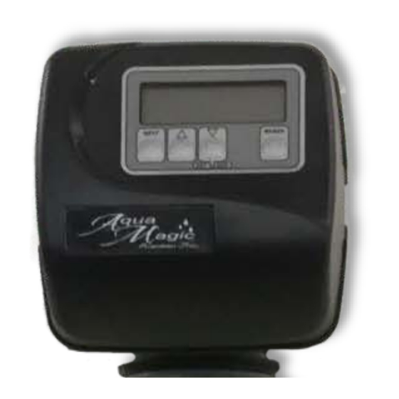
User Displays General Operation When the system is operating, one of four displays may be shown. Pressing NEXT will alternate between the displays shown below. User 1 Displays number of days to next regeneration. User 2 Flow Rate. Displays present flow rate. Not applicable for Guardian Series Systems. User 3 Displays total volume in gallons since last reset. -
Page 8: Installer Display Settings
Installer Display Settings STEP 1I STEP 1| - Press NEXT and simultaneously for 3 seconds. Press NEXT to advance through the programming settings. STEP 2I STEP 2| – Day Override: Sets the number of days between regenerations. Set Day Override using ... - Page 9 Regeneration Mode 8:00 Typically a system is set to regenerate at a time of low water usage. An example of a time with low water usage is when a household is asleep. If there is a demand for water when the system is regenerating, untreated water will be used.
-
Page 10: Parts Breakdown
Front Cover and Drive Assembly Drawing No. Order No. Description Quantity V3175EE-01 AM1 Front Cover Assembly V3107-01 AM1 Motor V3106-01 AM1 Drive Bracket & Spring Clip V3408EE-04BOARD AM1 Thru/2EE PCB 5 Digit Replacement V3110 AM1 Drive Gear 12x36 V3109 AM1 Drive Gear Cover V3186 AM1 AC Adapter 120V Not Shown... - Page 11 Drive Cap Assembly, Downflow Piston, Upflow Piston, Regenerant Piston and Spacer Stack Assembly Drawing No. Order No. Description Quantity V3005-02 AM1 Spacer Stack Assembly V3004 Drive Cap ASY Back Plate Refer to Programming and Cover Drawing Manual V3011 AM1 Piston Downflow ASY V3174 AM1 Regenerant Piston V3135...
- Page 12 Injector Cap, Injector Screen, Injector, Plug and O-Ring Drawing No. Order No. Description Quantity V3176 INJECTOR CAP V3152 O-RING 135 V3177-01 INJECTOR SCREEN CAGE V3010-1F AM1 INJECTOR ASY F BLUE V3010-1H AM1 INJECTOR ASY H GREEN Page 12...
- Page 13 Refill Control and Check Valve Drawing No. Order No. Description Quantity H4615 Elbow Locking Clip H4628 Elbow 3/8” Liquifit V3163 0-ring 019 NeoOV15 15 MM Check Valve V4144-01CV Elbow 3/8 Liquifit Asy w/RFC Brine Screen with Tube ABPUS1 Flow Proper check valve orientation allows for air to enter system during brine draw cycle.
- Page 14 Drain Line – 3/4” Drawing No. Order No. Description Quantity H4615 Elbow Locking Clip AM1 Drain Elbow ¾ Male V3158-01 O-ring 019 V3163 V3159-01 AM1 DLFC Retainer ASY One DLFC V3162-053 AM1 DLFC 5.3 gpm for ¾ must be used if ¾ fitting is V3162-100 AM1 DLFC 10.0 gpm for ¾...
- Page 15 Water Meter, Meter Plug and Mixing Valve Drawing No. Order No. Description Quantity V3151 AM1 Nut 1” QC V3003* AM1 Meter ASY V3118-01 AM1 Turbine ASY V3105 O-ring 215 V3003-01 AM1 Meter Plug ASY Used With Guardian *Order number V3003 includes V3118-01 AM1 Turbine ASY and V3105 O-ring 215. THIS WATER METER SHOULD NOT BE USED AS THE PRIMARY MONITORING DEVICE FOR CRITICAL OR HEALTH EFFECT APPLICATIONS.
- Page 16 Bypass Valve Drawing No. Order No. Description Quantity V3151 AM1 Nut 1” Quick Connect V3150 AM1 Split Ring V3105 O-Ring 215 V3145 AM1 Bypass 1” Rotor V3146 AM1 Bypass Cap V3147 AM1 Bypass Handle V3148 AM1 Bypass Rotor Seal Retainer V3152 O-ring 135 V3155...
- Page 17 Service Spanner Wrench (Order No. V3193-02) Although no tools are necessary to assemble or disassemble the valve, the AM1 wrench (shown in various positions on the valve) may be purchased to aid in assembly or disassembly. Loosens Injector And Bypass Caps Loosens Drive Cap Page 17...
- Page 18 Quantity Part Number Description CIOX-V1EEDTF CIOX Valve D601F Distributor Tube CL1054N Mineral Tank CL1354N Mineral Tank 1.5/2.5 Filter Media D1225-15 Air Disperser V3006 Bypass Assembly V3191-01CV Elbow Assembly with CV* V4144-01CV Brine Elbow with CV V3158-01 Drain Assembly *Must be installed in downward position **Consult dealer for correct media replacement...
-
Page 19: Troubleshooting
TROUBLESHOOTING Problem Cause Solution A. Transformer unplugged A. Connect to Power 1. Blank or unreadable LCD B. Defective transformer B. Check to ensure 12 volt display motor, replace transformer C. No electric power at outlet C. Repair outlet or switch to working outlet D. -
Page 20: Warranty
FRAKCO, INC. will replace or repair the defective item. Replacement of a defective item will be at FRAKCO’S factory in Luverne, MN, and the purchaser must ship the defective item at its own expense to FRAKCO’S factory.
Need help?
Do you have a question about the Aqua Magic Guardian Series and is the answer not in the manual?
Questions and answers