Table of Contents
Advertisement
���������� ������
GB
� ������������ ��� ������� �������� � � � ���� �
������������ �� ��� �������� ��������� �������
SERVO 25
(MaschNr + . . 01001)
SERVO 25 NOVA
(MaschNr + . . 01001)
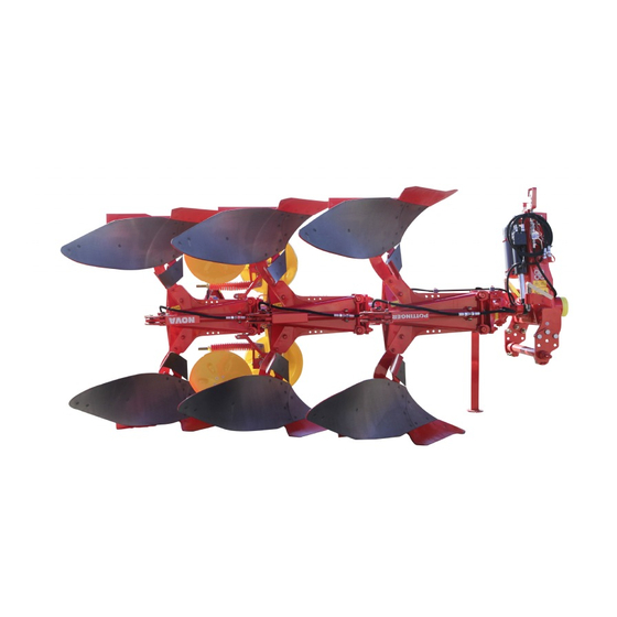
Plough
99 987.GB.80H.0
���
Ihre / Your / Votre • Masch.Nr. • Fgst.Ident.Nr.
Ihre / Your / Votre • Masch.Nr. • Fgst.Ident.Nr.
Advertisement
Table of Contents

Related Manuals for Pottinger SERVO 25


Summary of Contents for Pottinger SERVO 25
- Page 1 ��� ������������ �� ��� �������� ��������� ������� SERVO 25 (MaschNr + . . 01001) SERVO 25 NOVA (MaschNr + . . 01001) Plough Ihre / Your / Votre • Masch.Nr. • Fgst.Ident.Nr. Ihre / Your / Votre • Masch.Nr. • Fgst.Ident.Nr.
- Page 2 Dear Farmer You have just made an excellent choice. Naturally we are very happy and wish to congratulate you for having chosen Pöttinger. As your agricultural partner, we offer you quality and efficiency combined with reliable servicing. In order to assess the spare-parts demand for our agricultural machines and to take these demands into consideration when developing new machines, we would ask you to provide us with some details.
- Page 3 INSTRUCTIONS FOR Dokument PRODUCT DELIVERY ALOIS PÖTTINGER Maschinenfabrik GmbH GEBR. PÖTTINGER GMBH A-4710 Grieskirchen Servicezentrum Tel. (07248) 600 -0 D-86899 Landsberg/Lech, Spöttinger-Straße 24 Telefax (07248) 600-511 Telefon (0 81 91) 92 99-130 / 231 Telefax (0 81 91) 59 656 GEBR.
-
Page 4: Table Of Contents
CONTENTS Table of contents Meaning of warning signs ..................................... 5 Preparations on the tractor ....................................6 Hydraulic control on the lifting gear ..................................6 Hydraulic connection ......................................7 Preparations on the plough ....................................7 Attaching to the tractor ......................................8 Removal from tractor ...................................... -
Page 5: Meaning Of Warning Signs
WARNING SIGNS CE sign The CE sign, which is affixed by the manufacturer, indicates outwardly that this machine conforms to the engineering guideline regulations and the other relevant EU guidelines. EU Declaration of Conformity (see supplement) By signing the EU Declaration of Conformity, the manufacturer declares that the machine being brought into service complies with all relevant safety and health requirements. -
Page 6: Preparations On The Tractor
ATTACHING TO THE TRACTOR Preparations on the tractor General Please observe the power range limits of the tractor being used. Wheels - Air pressure in the tractor’s rear tyres when ploughing should be 0.8 bar. - Under difficult operating conditions additional wheel weights can be advantageous. -
Page 7: Hydraulic Connection
ATTACHING TO THE TRACTOR Hydraulic connection 1 Double-action control unit Preparations on the plough Mounting axle 825 mm • Carry out adaption to the tractor´s lifting gear - both helical plates can be fitted in 4 different positions (P1, P2, P3, P4) Upper link pins Position upper link pins (6) as per diagram... -
Page 8: Attaching To The Tractor
ATTACHING TO THE TRACTOR Attaching to the tractor Parking stand - Using the control lever Safety advice: (8), release parking stand, swing up and See supplement A1, Pt. 8a-h back and lay in the clamp - Switch tractor’s hydraulics to control position. (9). -
Page 9: Before Driving To The Field
PRESETTING THE PLOUGH Before driving to the field SERVO SERVO NOVA see next page SERVO PLUS SERVO NOVA PLUS 1. Carry out basic setting according to table B, with average cutting width position. 2. Carry out a more accurate setting when in use. Setting both the spindles (ZP, VF) Drawing point (ZP) Backfurrow (VF) -
Page 10: Before Driving To The Field
PRESETTING THE PLOUGH Before driving to the field SERVO 1. Carry out basic setting according to table C. 2. Carry out a more accurate setting when in use. SERVO NOVA 1. Carry out basic setting according to table A. 2. Carry out a more accurate setting when in use. Set furrow width - Loosen both hexagonal screw (SK). -
Page 11: Fine Setting (Measurement F)
PRESETTING THE PLOUGH 165-02-11 Example: Fine setting (measurement F) A = 416 mm Fine setting adapts the plough to the tractor in use and therefore is to be B = 931 mm carried out only once. W = 80 mm With that the fine adjustment spindle is set at the etablished measurement (W = 200 mm) The intersecting point (F) lies between the lines "306"... -
Page 12: Setting The Plough To The Tractor Using
OPERATION Setting the plough to the tractor using "Servomatic" „SERVOMATIC“ enables the optimum adaption of plough to tractor. The following setting controls should be carried out in order. 1. Fine setting (F) - Check setting measurement for fine adjustment spindle (F). See chapter "PRESETTING THE PLOUGH". -
Page 13: Turning The Plough Over
OPERATION Turning the plough over Beware! Nobody is to stand within the swinging range during turning. Turning procedure is only to be actuated from the tractor cabin. The plough must be completely raised to turn. The automatic reversing gear enables the whole turning procedure to be carried out through only one single switch position on the control unit (ST). -
Page 14: Ploughing With Hydraulic Control
OPERATION Ploughing with hydraulic control So that the hydraulic control functions properly, the following must be observed. - Position upper link (1) so that the attachment point (P1) on the plough during operation is somewhat higher than the attachment point (P2) on the tractor. TD65/92/27 Pinning the upper link LL, RL = Pinning position for securing lower link... -
Page 15: Shear Bolts
OVERLOAD SAFETY Shear bolts The ploughing components are fastened with shear bolts. When overloaded the shear bolts break (30) and the ploughing component swings away and up. - Remove the rest of the shear bolt. - Loosen hexagonal bolt (31). - Swing ploughing component back into the working position. -
Page 16: Fully Automatic „Nonstop" Overload Safety
SERVO NOVA Fully automatic „Nonstop“ overload safety Nitrogen pressure in the gas accumulator (43) (Factory set) 80 bar The fully automatic overload safety is recommended for soils Pressure adjustment area of the hydraulic cylinder (40) which are difficult to plough e.g. soil with stones or other foreign 90 to 160 bar bodies. -
Page 17: Gas Accumulator (43)
SERVO NOVA Gas accumulator (43) Pressure in the gas accumulator can also be altered. A reduction or increase of gas pressure in the accumulator depends upon the various soil types. • With very light soil the gas pressure can be somewhat reduced. Important! •... -
Page 18: General Maintenance Advice
MAINTENANCE AND SERVICE General maintenance advice Cleaning the machine parts Take note! In order to keep the implement in good condition even after a long Do not use a high pressure cleaner to clean bearings or hydraulic service life, please observe the following points: parts. -
Page 19: Setting The Ploughing Component Tilt
MAINTENANCE AND SERVICE Setting the ploughing component tilt If the plough is not penetrating the ground correctly, an improvement can be obtained by turning the eccentric bush. • The blade point in the area „S“ is set either higher or lower depending upon the position of the eccentric bush (A or B). -
Page 20: Setting The Disk Coulter
ADDITIONAL DEVICES Setting the disk coulter Pre-ploughing implements • Set the cutting depth of the disk coulter at a gap of 5 cm to the Maize skimmer, Manure skimmer ploughing blade tip. These implements are designed to incorporate surface trash straw or manure in the soil. -
Page 21: Double Feeler Wheel
FEELER WHEELS Double feeler wheel • The double feeler wheel is fitted to the last ploughing component. • The working depth is set via the spindle (70) using the accompanying ratchet. • When ploughing with a 4 blade plough the double feeler wheel can be fitted to the second last ploughing component. -
Page 22: Extension Arm With Hydraulic Releasing Device For Packer And Trailing Implements
PLOUGH-TRAILING IMPLEMENTS Optional equipment Extension arm with hydraulic releasing device for packer and trailing implements • A double-action control unit is necessary on the tractor. • The extension arm is fitted to the main frame. • A T screw fitting with a plug-in coupling sleeve is fitted to the return line (T) on the plough turning cylinder. Working position •... -
Page 23: Disconnect The Arm
PLOUGH-TRAILING IMPLEMENTS Disconnect the arm 1. Disconnect the hydraulic pipe (Hyd) 2. Take away the two axles (B1, B2) 3. Take the arm from the bearings Adjusting the amortisation effect With the arm two springs are delivered (F1,F2) They reduce shocks wenn the trailing implement is penetrating Depending on the weight of the trailing implement it is necessary to chose the right spring... -
Page 24: Extension Arm With Hydraulic Releasing Device For Packer And Trailing Implements
A3 - Abstand ca. 60 cm größer als A1 der Fangposition ausgeglichen A4 - Abstand ca. 90 cm größer als A1 werden. A5 - größter Abstand Optional extra for SERVO 25 S, SERVO 35 S, SERVO 45 S 115-07-04 - 24 - 0700_GB-SCHWENKAUSLEGER_983... -
Page 25: Working With A Trailing Implement
PLOUGH-TRAILING IMPLEMENTS Working with a trailing implement For attachment a latching device is fitted to the trailing implement which lies at right angles to the direction of travel. Arbeitsposition Fangposition 115-07-03 115-07-05 Engaging the trailing implement Pflügen ohne Nachlaufgerät • Bolts in the locking position (81v). •... - Page 26 PLOUGH-TRAILING IMPLEMENTS Demontage: 1. Hydraulikleitung abkuppeln. 2. Zugfeder (Z) demontieren. 3. Lagerbolzen (B) entfernen. 4. Auslegerarm (A) herausnehmen. 115-07-01 Aufbau bei "PLUS" - Pflügen Bei PLUS-Pflügen ist eine Steuerkette (S) zu montieren. Mit dieser Steuerkette wird, je nach Kettenlänge, die Take note! Fangposition des Auslegerarmes (A) eingestellt.
-
Page 27: Defined Use Of The Plough According To The Manufacturer's Instructions
TECHNICAL DATA Vehicle Identification Plate • The implement’s exact designation and its fittings (frame height, component form, ...) are imprinted in the section „Type“. • The factory number is imprinted on the vehicle identification plate (as shown opposite) and on the attachment frame. Guarantee claims and queries cannot be processed without the serial number being supplied. -
Page 28: Technical Data
TECHNICAL DATA Technical data Permanent sound emmission level < 70 dB(A) Power requirement max. 103 kW / 140 hp SERVO 25 Standard Type Blades Component distance Frame height Cutting width Weight Power requirement from (kW / PS) SERVO 25-385 72 / 78... -
Page 29: Optional Equipment
TECHNICAL DATA Optional Equipment Trashboard Leg deflector Guiding plate Knife coulter Landside saver UW, UWS, W, WSS. U, UW, UWS, W, WSS. U, UW, UWS. U, UW, W, WSS. UW, UWS, W, WSS Maize mulcher Manure mulcher - skim coulter Smooth disk coulter Cutaway disk coulter Subsoiler... -
Page 30: Plough Body Forms
EQUIPMENTS Plough body forms Description • Easy to pull 31 UW 36 UW • Excellent clod breaking 39 UW • Suitable for all soils 35-26 W • Especially for slopes/shallow plougling 36 W • Easy to pull 35 W • Very good characteristics for newly 41 W ploughed fields The small slatted body... - Page 31 SUPPLEMENT GB-Anhang Titelblatt _BA-Allgemein...
- Page 32 The original cannot be copied ... Things will run better with genuine Pöttinger parts • Quality and precise fitting The decision must be made, ”original” or ”imitation”? The decision is often governed by price and a ”cheap buy” can sometimes be very expensive. - Operating safety.
- Page 33 SUPPLEMENT - A Recommendations for work safety Recommendations for work safety 6.) Transport of persons prohibited All points refering to safety in this manual are indicated a. The transport of persons on the machine is not permitted. by this sign. b.
- Page 34 [mm] [mm] [mm] [mm] 1000 1100 1200 1300 1400 1500 102 cm 165-02-12 TD65/92/35 165-02-02 Type: SERVO 25 NOVA Blades: Cutting width 35 cm 40 cm 44 cm 48 cm Position [mm] [mm] [mm] [mm] [mm] [mm] [mm] [mm] [mm]...
- Page 35 [mm] [mm] 1000 1100 1200 1300 1400 1500 165-02-12 102 cm 102 cm TD65/92/35 165-02-09 Type: SERVO 25 NOVA Blades: 3 (2+1) Cutting width 35 cm 40 cm 44 cm 48 cm Position [mm] [mm] [mm] [mm] [mm] [mm] [mm]...
- Page 36 TABLE 102 cm 102 cm 102 cm 165-02-12 TD65/92/35 165-02-13 Type: SERVO 25 Blades: 4 (3+1) Cutting width 35 cm 40 cm 44 cm 48 cm Position [mm] [mm] [mm] [mm] [mm] [mm] [mm] [mm] [mm] 1000 1100 1200 1300...
- Page 37 [mm] [mm] [mm] [mm] 1000 1100 1200 1300 1400 1500 95 cm 165-02-12 TD65/92/35 165-02-05 Type: SERVO 25 NOVA Blades: Cutting width 33 cm 37 cm 41 cm 45 cm Position [mm] [mm] [mm] [mm] [mm] [mm] [mm] [mm] [mm]...
- Page 38 TABLE 165-02-12 95 cm 95 cm TD65/92/35 165-02-04 Type: SERVO 25 Blades: Cutting width 33 cm 37 cm 41 cm 45 cm Position [mm] [mm] [mm] [mm] [mm] [mm] [mm] [mm] [mm] 1000 1100 1200 1300 1400 1500 95 cm...
- Page 39 TABLE 95 cm 95 cm 165-02-12 TD65/92/35 165-02-10 Type: SERVO 25 NOVA Blades: 3 (2+1) Cutting width 33 cm 37 cm 41 cm 45 cm Position [mm] [mm] [mm] [mm] [mm] [mm] [mm] [mm] [mm] 1000 1100 1200 1300 1400...
- Page 40 1000 1100 1200 1300 1400 1500 95 cm 95 cm 95 cm 165-02-12 TD65/92/35 165-02-06 Type: SERVO 25 NOVA Blades: 4 (3+1) Cutting width 33 cm 37 cm 41 cm 45 cm Position [mm] [mm] [mm] [mm] [mm] [mm] [mm]...
- Page 41 [mm] [mm] 1000 1100 1200 1300 1400 1500 85 cm 85 cm 165-02-12 TD65/92/35 165-02-07 Type: SERVO 25 NOVA Blades: Cutting width 33 cm 36 cm 40 cm 43 cm Position [mm] [mm] [mm] [mm] [mm] [mm] [mm] [mm] [mm]...
- Page 42 1000 1100 1200 1300 1400 1500 85 cm 85 cm 85 cm 165-02-12 TD65/92/35 165-02-08 Type: SERVO 25 NOVA Blades: 4 (3+1) Cutting width 33 cm 36 cm 40 cm 43 cm Position [mm] [mm] [mm] [mm] [mm] [mm] [mm]...
-
Page 45: Combination Of Tractor And Mounted Implement
Important! Additional Information Combination of tractor and mounted implement The mounting of implements on the front or rear three point linkage shall not result in exceeding the maximum permissible weight, the permissible axle loads and the tyre load carrying capacities ot the tractor. The front axle of the tractor must always to be loaded with at least 20 % of the unladen weight of the tractor. - Page 46 Important! Additional information Combination of tractor and mounted implement CALCULATION OF THE REAL FRONT AXLE LOAD T V tat (If with the front mounted implement (G ) the required minimum front ballasting (G ) cannot be reached, the weight of the front mounted V min implement has to be increased to the weight of the minimum ballasting at the front!) Record the calculated real front axle load and the permissible front axle load of the tractor into the table.
- Page 47 ����� ������� �� ������� � ����� ���� �������� ���������� ������ ������ ��� ������ ������� ���� ����� ��� ������� ���� ��� ������������� declare in sole responsibility, that the product Drehpflug SERVO 25 SERVO 25 NOVA __________________________________________________________________________ ������ ������ to which this certificate applies, conforms to the basic safety and health requirements of EEC Directions 98/37, ���...
- Page 48 Im Zuge der technischen Weiterentwicklung La société PÖTTINGER Ges.m.b.H améliore Following the policy of the PÖTTINGER arbeitet die PÖTTINGER Ges.m.b.H ständig constamment ses produits grâce au progrès Ges.m.b.H to improve their products as tech- an der Verbesserung ihrer Produkte. technique. C'est pourquoi nous nous réser- nical developments continue, PÖTTINGER vons le droit de modifier descriptions et illustrations reserve the right to make alterations which must not...
- Page 49 ALOIS PÖTTINGER Maschinenfabrik Gesellschaft m.b.H A-4710 Grieskirchen Telefon: 0043 (0) 72 48 600-0 Telefax: 0043 (0) 72 48 600-511 e-Mail: landtechnik@poettinger.co.at Internet: http://www.poettinger.co.at GEBR. PÖTTINGER GMBH Stützpunkt Nord Steinbecker Strasse 15 D-49509 Recke Telefon: (0 54 53) 91 14 - 0 Telefax: (0 54 53) 91 14 - 14 PÖTTINGER France 129 b, la Chapelle...
Need help?
Do you have a question about the SERVO 25 and is the answer not in the manual?
Questions and answers