Sensus 243-12-1 Installation And Maintenance Instructions Manual
Service regulators
Hide thumbs
Also See for 243-12-1:
- Manual (25 pages) ,
- Installation and maintenance instructions manual (8 pages)
Advertisement
Quick Links
Introduction
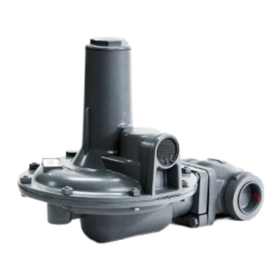
The 243 is a large capacity general-purpose gas pressure
regulator.
Its outstanding performance and versatility make it an excellent
choice for use on industrial meter sets, combustion equipment,
boilers, burners, unit heaters, furnaces, ovens and other appli-
cations.
Use it for natural gas, air, dry CO
nitrogen, and others. Special materials are available for cer-
tain corrosive gases.
In addition to the standard models and internal relief models
covered in this bulletin, the 243 is also available with low pres-
sure cut-off, with built-in monitor, and as a pilot operated regu-
lator (outlet pressures to 35 psig), a back pressure valve, a
relief valve, a vacuum regulator and a vacuum breaker. For
information, please contact your Sensus Sales Office or
authorized industrial distributor. The 243 is manufactured in
conformance with Code B31.8.
Note: The term standard refers to Non-IRV configurations.
Model Specifications
243-12-1 and 243-12-2
Maximum Inlet Pressure.........................................125 psi
Outlet Pressures......................................3
Pipe Sizes................................................ 1
Diaphragm..................................... 12" (nominal diameter)
243-8-1 and 243-8-2
Maximum Inlet Pressure.........................................125 psi
Outlet Pressures..................................3
Pipe Sizes................................................ 1
Diaphragm....................................... 8" (nominal diameter)
243-8HP
Maximum Inlet Pressure.........................................125 psi
Outlet Pressures................................................3 to 10 psi
Pipe Sizes................................................ 1
Diaphragm....................................... 8" (nominal diameter)
Maximum Inlet Pressures
ORIFICE SIZE - VALVE
243-12
1
1
15 psi
1
1
25 psi
*
1" - 30
25 psi
1" - 10
40 psi
*
3
40 psi
t
3
60 psi
1
⁄
100 psi
2
3
125 psi
1
125 psi
.207" - 10
• • •
* Applies only to 243-12 with external control line.
80 psi for 243-12 with external control line
t
Temperature Limits
The Model 243 Service Regulators can be used for flowing
temperatures from -20 F to 150 F.
O
Buried Service
The Model 243 Service Regulators are not recommended for
buried service.
, propane, butane, L.P.G.,
2
1
⁄
" w.c. to 3 psi
2
1
⁄
", 1
1
⁄
" and 2"
4
2
1
⁄
" w.c. to 4
1
⁄
" psi
2
4
1
⁄
", 1
1
⁄
" and 2"
4
2
1
⁄
", 1
1
⁄
" and 2"
4
2
243-8
⁄
" - 30
O
• • •
4
⁄
" - 10
O
• • •
4
25 psi
O
25 psi
O
40 psi
⁄
" - 30
O
4
40 psi
⁄
" - 10
O
4
80 psi
" - 10
O
100 psi
⁄
" - 10
O
8
125 psi
⁄
" - 10
O
4
125 psi
O
O
Regulator Installation and
Maintenance Instructions
243 Service
Regulators
Installation and Start Up
(See Illustrations on Page 3.)
1. Make certain that regulator and piping are free of dirt,
moisture, foreign matter and other debris.
2. Be sure all shipping screens or covers are removed and
regulator is installed with flow in correct direction.
3. Regulator may be installed in any position; right-side-up, up-
side down, vertical pipe, horizontal pipe, diagonal pipe, etc.
By loosening union bolts (16), the diaphragm case assembly
may be rotated to various positions in relation to the body.
Make certain (16) are re-tightened to hold diaphragm case
assembly in new position and to reseal.
CAUTION
The diaphragm case vent must be positioned
to protect against flooding, drain water, ice
formation, traffic, tampering, etc. The vent
must be protected against nest building
animals, bees, insects, etc. to prevent vent
blockage and minimize the chances for
foreign material from collecting in the vent
side of the regulator diaphragm.
4. Make sure there are no leaks and all connections are firm
and tight. Tighten flange bolts evenly and firmly. On screwed
connections apply pipe dope to male threads only.
5. On regulators arranged for External Control Line, run pipe
or tubing from
1
⁄
" NPT connection in lower case to the con-
2
trol connection in the outlet piping.
should not be less than
⁄
" in size and should be adequately
1
2
protected against breakage (regulators go wide open if the
control line is broken). In general, the control connection
should be at least 8 pipe diameters from the regulator and in
as straight a run of pipe as possible. The connection itself
must be smooth on the inside of the pipe. Pitch the control
line away from the regulator and avoid moisture pockets.
Keep inside of control line clean. Never install any type of
automatic shut-off device, which closes completely, between
the regulator outlet and the control line connection.
CAUTION
It is the user's responsibility to assure that all
regulator vents and/or vent lines exhaust to a
non-hazardous location away from any potential
sources of ignition. Where vent line are
used, it is the user's responsibility to assure
that each service regulator is individually vented
and that common vent lines are not used.
6. Adjust outlet pressure (set point) by removing cap (1) or
(1e) and turning adjustment spring button (3). On 243-8 HP
remove cap (1a), loosen locknut and turn adjustment screw
(1b). Turn clockwise to increase and counter-clockwise to
decrease outlet pressure. Only adjust when gas is flowing
through regulator. When adjustment is completed, seal cap
(1) or (1e) must be securely screwed into place.
absence of this seal cap can result in unstable operation.
RM-1306-1 Rev. 11
This control piping
The
Advertisement

Related Manuals for Sensus 243-12-1


Summary of Contents for Sensus 243-12-1
- Page 1 (outlet pressures to 35 psig), a back pressure valve, a relief valve, a vacuum regulator and a vacuum breaker. For CAUTION information, please contact your Sensus Sales Office or authorized industrial distributor. The 243 is manufactured in The diaphragm case vent must be positioned conformance with Code B31.8.
- Page 2 (11k) used. ILL. Part Description Number Internal Relief Valves must be carefully sized. For informa- tion, contact your Sensus Representative. Cover Cap (IRV) 143-16-005-00 143-16-005-08 Cover Cap (STD) 6. Regulators installed indoors must be vented outside. Run...
-
Page 3: Pipe Sizes
10” (STD COVER CAP) Vent - as shown - 1” NPT 1 1k 1 1b 1 1a 243-12-1 ⁄ ” Same as I.R.V. Regulator except no Internal Relief Valve and Standard Cover Cap as shown in inset. 7” or 10”... -
Page 4: Correction Factor
OTHER GASES CORRECTION FACTOR ignition systems. A travel stop stem is located in the 243-12-1 and 243-12-4 to provide over pres Air (Specific Gravity 1.0) 0.77 surization protection to internal components dur ing overpressurization. - Page 5 CONDENSED CAPACITY TABLE IN SCFH OF NATURAL GAS (O.6 Specific Gravity-14.65 psia-60 F.) OUTLET PRESSURE SER POINT and SPRING ORIFICE INLET SIZE 6” w.c. 7” w.c. 11” w.c. 18” w.c. 1 psi 2 psi BLUE GREEN ORANGE BLACK CADMIUM PRESSURE SPRING SPRING SPRING...
- Page 6 Sensus Metering Systems, 805 Liberty Boulevard, DuBois, PA 15801 (814) 371-8000 FAX (814) 375-8460 Representatives in all principal cities. Distributors throughout the world. 805 Liberty Boulevard DuBois, PA 15801 QUALITY SYSTEM REGISTERED TO ISO 9001 Authorized Distributor: LIMITED WARRANTY Seller warrants the Goods to be free from defects in materials manufac- tured by Seller and in Seller’s workmanship for a period of [one (1) year] after tender of deliv-...
Need help?
Do you have a question about the 243-12-1 and is the answer not in the manual?
Questions and answers