SOMNOmedics SOMNOtouch RESP Instruction Manual
Hide thumbs
Also See for SOMNOtouch RESP:
- Instruction manual (120 pages) ,
- Instruction manual (13 pages)
Table of Contents

Related Manuals for SOMNOmedics SOMNOtouch RESP


Summary of Contents for SOMNOmedics SOMNOtouch RESP
- Page 1 RESP Caution: Federal law restricts this device to sale by or on the order of a physician. SOMNOmedics GmbH Am Sonnenstuhl 63 – 97236 Randersacker – Germany Phone: (+49) 931 / 35 90 94-0 – Fax: (+49) 931 / 35 90 94-49...
- Page 2 Am Sonnenstuhl 63 – 97236 Randersacker – Germany Phone: (+49) 931 / 35 90 94 - 0 – Fax: (+49) 931 / 35 90 94 - 49 Rev. 0 29.01.2015 All proper names marked with TM are copyright protected by SOMNOmedics. - 2 -...
-
Page 3: Table Of Contents
Index Introduction ............................. 6 Intended Use / Indication of Use ....................6 Overview ............................. 6 Patients ............................7 About this instruction manual ..................... 7 Explanation of Symbols used in this Manual ................7 About the SOMNOtouch™ RESP....................8 Type Label ..........................8 Elements of keyboard ....................... - Page 4 7.3.3.2 Activity Analysis ......................57 7.3.3.3 Flow Analysis ......................58 7.3.3.4 Snore Analysis ......................60 7.3.3.5 Phase Angle Analysis ....................60 7.3.3.6 Position Analysis ....................... 61 7.3.3.7 Effort Analysis ......................61 7.3.3.8 Analysis ......................62 7.3.3.9 CPAP Analysis ......................63 7.3.4 Menu - Analysis Channels ....................
- Page 5 Maintenance rate ........................92 Cleaning and Disinfection ......................92 Use and Maintenance of the Rechargeable Battery ..............93 Functional Testing of the integrated Pulse Oximeter ............... 93 10 Service ............................94 10.1 Technical specification ......................94 10.2 Lifetime ........................... 95 10.3 Storage ...........................
-
Page 6: Introduction
1 Introduction The SOMNOmedics team would like to thank you for purchasing this product. We are confident that you will enjoy using the SOMNOtouch™ RESP for many years. The SOMNOtouch™ has been developed by SOMNOmedics to meet the highest quality control standards available. -
Page 7: Patients
SOMNOtouch™ RESP does not provide automatic diagnosis and is not designed to be used in Life Support situations. 1.3 Patients The SOMNOtouch RESP and its components may only be used as follows: For adult patients Excluded are monitored and intensive care patients 1.4 About this instruction manual... -
Page 8: About The Somnotouch™ Resp
2 About the SOMNOtouch™ RESP Status LED’s External Signal Internal Beeper Input (AUX) Interface/Charger Connector On/Off Button External Signal Internal Effort Sensor Input (AUX) Marker Button Input for SpO Sensor Body Position Sensor Luer Lock® for Nasal cannula Acceleration Sensor (X,Y &... - Page 9 Manufacturer information / address This device has no SpO2 alarm Additionally you receive information on the serial number and current firmware of the device when you press the SOMNOmedics logo in the start display: SN: TOR 0034 Firmware: 1.0 Hotline: +49 931 359094 994 www.somnmedics-diagnostics.com...
-
Page 10: Elements Of Keyboard
2.2 Elements of keyboard Picture Description Function Green LED Yellow LED Idle & Waiting Mode Status LED 1 Recording Mode flashes 16x /s off Initialisation / data transfer Recording 2s on Error during initialisation + beep When this LED is Yellow, the battery is being charged Status LED 2 When this LED gets off while device... -
Page 11: Configuration
2.3 Configuration The configuration includes a SOMNOtouch™ RESP basic device, a thorax effort belt, an SpO sensor, one abdomen effort sensor and belt, the nasal cannula with filter, the docking station and power supply, a USB adapter cable, a carry bag for storing or transporting the SOMNOtouch™ RESP, the instruction manual and the DOMINO light software for initialization, data transfer and analysis. -
Page 12: Safety Instructions
SOMNOtouch™ RESP. Only sensors designed and supplied by SOMNOmedics may be used with this unit. All sensors are provided unsterile and should never be sterilized. This device is not to be used on broken skin. If this device comes in contact with broken skin/blood, do not reuse this device and discard. - Page 13 Opening the case, repairing or modifying the SOMNOtouch™ RESP in any way will void the guarantee and might affect the safety of the device. Only SOMNOmedics and its authorised distributors may repair the unit. Always use the Docking Station (TOS900) to charge the internal battery.
-
Page 14: Installing The Domino Light Software
4 Installing the DOMINO light Software Please note the System Requirements for running DOMINO light Software. Please also note that the Software must be activated by entering a Registration Code. You will find the file on the installation CD. Double click on this file to start the installation. Choose your language and click on button Next>. - Page 15 Accept the selection “New Installation” by clicking the Next button. Click “Next”. Start the installation process by clicking “Next”. The installation progress will be displayed by a running green bar. - 15 -...
- Page 16 When the installation is complete the software will ask if you want to install the USB driver for the Docking Station. Leave the default option for the first installation, you can use this to reinstall the USB- driver later if necessary. If “Run DOMINO light”...
- Page 17 Updating the Software To update your software version please install the new version in the same directory as the original version. During the installation you will be asked to choose one of the following installation types. New analysis, channels and features of the software are updated. The settings of analysis and analysis templates remain as before.
- Page 18 All existing settings are overwritten with the new standard settings of the software. Data safety notes: Personal patient data is stored on the computer when transferring measurements. Please take all necessary measures to protect data on the storage, such as i.e. automatic timed user session log offs, limit physical and network access to the storage device, use of layered authentication, use strong passwords Install DOMINO light only from thrustworthy sources such SOMNO-medics GmbH or...
-
Page 19: Manual Docking Station Driver Installation
5 Manual Docking Station Driver Installation 5.1 Windows 7 1. Connecting the Docking Station First, connect the Docking Station to a free USB-Slot of your Computer. After connecting the device with the USB-Port there are two possible options: Option 1 A dialog window “Update driver software…”... - Page 20 In the window “Device Manager” you will find an entry “Other devices”, underneath this entry there is a point “SOMNOtouch RESP”: Right click this entry, then a context menu appears. In this context menu left click on “Update Driver Software”.
- Page 21 3. Automatic driver software installation Windows 7 recognized that a new device has been plugged in and will gather the information about the USB device: Next step is to click “Browse my computer for driver software”. In the dialog window “Browse my computer for driver software” left-click on the button “Browse…”, choose the CD/DVD drive and change the directory to where you can find the SOMNOtouch USB driver: Activate the checkbox labeled “Include subfolders”, then click on the button “Next”.
- Page 22 Now you are able to use the connected SOMNOtouch™ RESP device. - 22 -...
-
Page 23: Operating Instructions
6 Operating Instructions Note: The SOMNOtouch™ RESP automatically switches to idle mode when no measurement is running. Start and end of a recording are programmed via the DOMINO light Software or the initialisation at the device. The date and time of the PC system clock are transferred to the SOMNOtouch™ RESP during initialisation. -
Page 24: Easystart
6.1.1 Easystart After a successful connection, the serial number, firmware version, hardware ID and the battery capacity are shown beneath the initialisation window (see Fig. 6-2). Fig. 6-2: Easystart DOMINOlight Enter the Patient data into the corresponding fields. Type carefully as this information will be saved for later use. -
Page 25: Advanced Mode
6.1.2 Advanced Mode After a successful connection, the serial number, firmware version, hardware ID and the battery capacity are shown beneath the initialisation window (see Fig. 6-3). Fig. 6-3: Patient Data Input. Enter the Patient data into the corresponding fields. Type carefully as this information will be saved for later use. - Page 26 Fig. 6-4: Menu “Montage” Create New Montage Used to create a new montage Save as… An existing montage may be saved with a different name after modification. The template has to be chosen according to the montage. Analysis template Example: respiratory recording ...
- Page 27 Fig. 6-5: Menu - Recording Start options: Manual start (1) Measurement is programmed to be started manually via the touch screen of the device. Auto Start (2) This option is used when the patient uses the SOMNOtouch™ RESP unattended. The unit will switch to Waiting Mode until the programmed time is reached.
-
Page 28: Starting The Somnotouch™ Resp At The Display
6.1.3 Starting the SOMNOtouch™ RESP at the display Press the ON button to activate the device. In the following menu the device can be started directly or a recording can be programmed, if not already done via PC (see 6.1). Fig. - Page 29 For a “Manual Start” the Start time is by default set to “now”, for “Auto start” it is the programmed time. The SOMNOtouch™ passes into the waiting mode of the Autostart if the start point is in the future. Fig. 6-8: Start menu Press to get back to the start display.
-
Page 30: Programmed Start Of The Somnotouch™ Resp
Tap on a single signal channel in the left to middle part of the display to see it in detail. To change the time range press on the time basis at the bottom left. Fig. 6-11: Signal To get back to the signal control press the return arrow. When all signals are to your satisfaction you can start the recording with the arrow to the right. -
Page 31: Attaching The Sensors
6.2 Attaching the Sensors a) Fit the SOMNOtouch™ RESP to the body strap. b) Connect the abdominal effort sensor to the SOMNOtouch™ RESP. c) Fit the effort belts around the patients Thorax and Abdomen. Select the correct belt size for the patient. - Page 32 d) Attach the nasal cannula and connect its plug to the nasal cannula filter and the filter to the Luer- ® Lock Adaptor Unit. Attachment of the nasal cannula filter: Connect the cannulas plug to the filter and the filter to the connector on the bottom of the SOMNOtouch™...
-
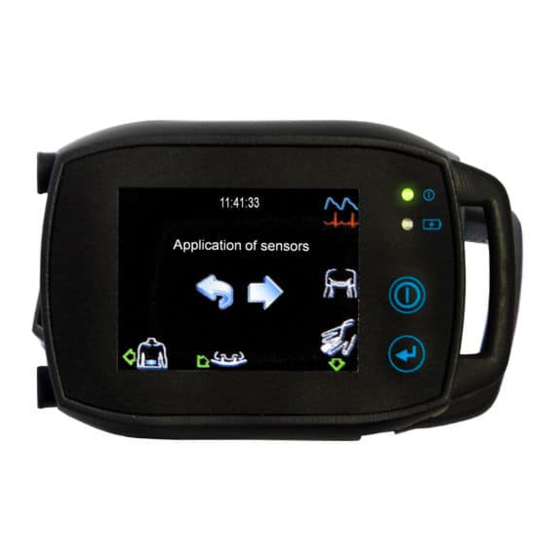
Page 33: Display During Recording
e) Attach SpO2 sensor finger left hand connect plug to the SOMNOtouch .RESP (1). Create a strain relief for the sensor cable with adhesive tape. Then connect the sensor to the SOMNOtouch™ RESP (2). Display during recording During the recording, the display can be activated by pressing the on/off button Fig. - Page 34 You receive information about the Heart Rate (HR), the oxygen saturation (SpO ),,battery status (1) and the current time (2). Also the programmed duration (3) and the recording duration so far (4) are shown. With active display a settings menu can be opened pressing the battery / time bar, which allows, to de- / activate the touch confirmation beep and the blinking of the LED during the recording respectively (the state to be activated is shown): Fig.
- Page 35 Tap on a single signal in the left to middle part of the display to see it in detail. Fig. 6-16: Signal To get back to the signal control tap the back arrow. The display will automatically shut off after 15 seconds. Please note: If one or more sensors are unplugged during the recording, a peep resounds, the display lights up and the missing sensor is highlighted by a green blinking arrow.
-
Page 36: Settings
6.3 Settings To change the settings, e.g. language, tap on the gearwheel symbol at the start display. Fig. 6-18: Start- display SOMNOtouch All settings which can be changed manually on the device will appear. Fig. 6-19: Settings For all settings the tick confirms the settings and a tap on the back arrow aborts the input. - 36 -... - Page 37 Sound The SOMNOtouch™ RESP provides a confirmation sound, when you tap a button on the touch screen. In the sound menu you can activate or deactivate the confirmation sound. Fig. 6-20: Sound Display In the display menu you can change the brightness of the display and the background colour for the menus.
-
Page 38: Manual Abortion Of The Recording
Language In the language settings you can choose the display-language. Fig. 6-23: Language 6.4 Manual abortion of the recording To abort a recording, you have to press the on/off button and the patient marker simultaneously for at least 2 seconds. The following screen will appear: Fig. -
Page 39: Data Transfer From Somnotouch™ Resp To Pc
6.5 Data Transfer from SOMNOtouch™ RESP to PC Once there is a measurement on the SOMNOtouch™ RESP, it is possible to transfer it to the computer via the Virtual Docking Station or the DOMINOlight panel. Please proceed as follows: Connect the SOMNOtouch™ RESP to the Docking Station. Press the On/Off Button if the charging cable is not connected. -
Page 40: Open A Recorded Measurement
6.6 Open a Recorded Measurement To open a recording, click on the Analysis symbol of the DOMINO light panel. The following window will open (Fig. 6-26): Click on Name or Start to sort measurements alphabetically Processing Status or chronologically Saved measurements Search Options... - Page 41 If you open a measurement, which has not previously been analysed, the Preferences Window will open. Please choose the “Respiratory” or “CPAP” template. CPAP recording: The measurement is automatically analysed according to the predefined parameters in the Global Preferences (see Chapter 7.3.3). The DOMINO light software marks analysed events in the Raw Data window by placing a coloured frames around each event.
- Page 42 Parameter Indicates position of the data in the Raw Data Window Time Bar Index/h Marker Analysis Time-base of Analysis (Change with right mouse button) Cursor Automatically marked Raw Data events Signal Scaling Time base of Raw Interactive Data (Change with Scroll Bar right mouse button) fig.
-
Page 43: Analysis
6.7 Analysis Define the Begin and the End of the measurement: Set Start Marker: Right click on the Raw Data area where you wish the Recording to Begin left click on “Define Start” Set End Marker: Right click in the Raw Data area where you wish the Recording to End left click on “Define End”... -
Page 44: Open The Report
Enter the Findings and the Diagnosis: Select Patient Info in the Tools menu left click on the tab sheet Diagnosis enter the Findings and the Diagnosis in the corresponding text fields The Choose Finding and Choose Diagnosis buttons offer lists of selectable predefined findings and diagnosis. - Page 45 User Data / Patient Data It is possible to edit this data by clicking on Patient Info in the Report Preview window. Recorded Time Complete recording time. Time in Bed (TIB) Period of time between the Lights off and Lights on markers. Respiratory Report Obstructive Number (Index): Number of Obstructive Apnea (index: per h of TIB).
- Page 46 A + H Number (Index): Number of Apnea and Hypopnea. Limitation Number (Index): Number of Flow Limitations. Number (Index): Respiratory Disturbance Index = “A + H” + “Limitations” Apnea (Index) Number of Apnea (index: per h of TIB). Hypopnea (Index) Number of Hypopnea.
- Page 47 Report Number of Desaturations Number of Desaturations (index: per hour of TIB). Minimal SpO2 (%) Indication of minimum SpO Average value of the SpO curve without considering the Baseline SpO2 Saturation events. Average SpO2 Average value of the complete SpO curve.
- Page 48 Snore Report Number of Snore events in a single body position (Prone, Supine, Snore (Index) Left, Right and Upright) during TIB (index: per h of TIB). Absolute Snore (min) Total duration of Snore events in each respective Position. Snore Episodes (min) Sum of all time intervals between 2 snore events if they are <...
- Page 49 Number of obstructive Apnea deduced from the raw data channels Obstructive Number(Index): Thorax and Abdomen (Index: designation per hour TIB). Number of central Apnea deduced from the raw data channels Central Number(Index): Thorax and Abdomen. Total A. Number(Index): Sum of all obstructive and central Apnea. Average Angle of Obstruction Average value of the obstruction level.
- Page 50 Summary The Summary provides an indication of the severity of the analysed parameters. Green = Normal, Yellow = Mild, Orange = Medium and Red = Severe. The calculations are based on all the parameters in relation to all the relevant bibliographical references. Anamnesis, Findings, Diagnosis, Comments It is possible to enter this information by clicking on Patient Info button.
-
Page 51: Domino Light Software
New releases of the DOMINO light Software are issued once or twice a year, as a result of our continued commitment to improving the system. These manuals are available free of charge for SOMNOmedics customers. The DOMINO light Software for SOMNOtouch is intended for use exclusively with the SOMNOtouch™... -
Page 52: Domino Light Panel
Before starting to use the Analysis Section of the software, it is necessary to activate it with a Registration Code. Please contact SOMNOmedics by fax, e-mail or telephone to obtain your Registration Code, you find the contact information in chapter 10.10. Please refer to fig. 7-2 for instructions on how to obtain and enter the Code. -
Page 53: Global Preferences
Preferences will be saved to a file. Computer-ID – phone SOMNOmedics support. Quote this number and you will be given the Registration Code to enter here. fig. 7-2: Global Preferences – Menu - Folders The default folder can be chosen from the Recordings Directory using the symbol. -
Page 54: Menu - Channels
Menu – Channels 7.3.2 In the Channels Menu the characteristics of the Raw Data Signal can be adjusted. Colour, Signal Scaling, Signal Direction and Channel Order can all be configured. The Channel Order can be changed by using the Drag & Drop function. Auto size of Limit values for Signal signals... -
Page 55: Menu - Analysis
Menu – Analysis 7.3.3 In this menu, all variables of the built-in algorithms can be changed. To display or change the parameters of an analysis, select the corresponding analysis type (i.e. Flow Analysis as marked in fig 7-4). Note: You can reset all parameters to default settings by performing an user defined update as described in section 4. -
Page 56: Sleep Wake Analysis
7.3.3.1 Sleep Wake Analysis The determination result from the Activity Analysis and if applicable the Body Position Analysis (Body Position = upright epoch is rated as WAKE). fig. 7-5: Sleep Wake Analysis 1) Ø Activity Threshold (Units) You can define the limit (threshold) a signal must exceed in relation to the baseline to be detected as activity. -
Page 57: Activity Analysis
7.3.3.2 Activity Analysis fig. 7-7: Activity Analysis Time-frame [s] Size of the Analysis-Timeframe in detection of Activity. Max. value: Activity is equal to the maximal value within the timeframe. Average value: Activity is equal to the value composed of the average value within the timeframe. Illustration Line: Bar:... -
Page 58: Flow Analysis
7.3.3.3 Flow Analysis Main purpose of the flow analysis is to support the user in the finding of hypopneas (partial reduction of breathing) and apneas (complete pauses in breathing). If the Flow signal gets lost during a recording, e.g. due to shifting of the cannula, the Flow Source can be changed (e.g. - Page 59 7) Central A: central part [%] (A: Apnea) This value indicates to what extend effort and flow events have to overlap in order to be identified as a Central Apnea. For example: If more than 50 % of an Apnea in the flow channel is overlapped by an effort event it will be scored as a Central Apnea.
-
Page 60: Snore Analysis
Activating this function will count an Apnea/Hypopnea event as sleep during the first wake stage after a respiratory event. The event however must start in a sleep stage. 14) Linearize Pressure The most accurate method of measuring the flow signal is to use two sensors: nasal cannula and thermistor, as recommended by the AASM guideline. -
Page 61: Position Analysis
2) Min. Increase [grad] Minimal increase of the phase angle chart, in order to classify a phase angle event. 3) Min. Duration [s] Minimal duration of the increase, in order to classify a phase angle event. 4) Max. Duration [s] Maximal duration of the increase, in order to classify a phase angle event. -
Page 62: Spo 2 Analysis
7.3.3.8 SpO Analysis The pulse oximeter uses an AASM conform 4 beat exponential averaging, to provide SpO2 results with a low latency and high accuracy. The quality of the SpO2 measurement can be also controlled by reviewing the not normalized pulse waveform which is provided as ‘Pleth’... -
Page 63: Cpap Analysis
7.3.3.9 CPAP Analysis fig. 7-17: CPAP Analysis The trend of the CPAP pressure is calculated in 15-second intervals and displayed. “Steps displayed in report” allows to choose the raster for pressure values displayed in the report. 7.3.4 Menu - Analysis Channels Within the Menu Analysis Channels the presentation of the analysis window can be formatted. -
Page 64: Menu - Filter
Menu – Filter 7.3.5 Mark the respective checkboxes to filter a specific signal. Settings (in Hz) for Highpass, Lowpass and Notch can be individually selected. The filter settings could be saved as a template (1). fig. 7-19: Menu Filter 7.3.6 Menu - Keys The Keys menu allows you set the keyboard keys to be used during manual editing. -
Page 65: Menu - Markers
7.3.7 Menu - Markers Markers can be set to indicate predefined events within a measurement. Adding markers: Enter the name of the marker in the field and click the button “Add marked Marker”. Renaming markers: Please select an existing marker from the list and click the button Edit Marker. -
Page 66: Menu - User Data
Menu – User Data 7.3.9 Enter the information you require to be printed as a heading for all reports. Should you wish to include your own logo on the report: Click on the Remove Image to clear the screen. Now activate the button Load Image and select the path where the logo is stored. -
Page 67: User Defined Report
The order of the Components in the Report can be rearranged by clicking the UP or DOWN symbols. Alternatively, the components can be moved using Drag & Drop. Note: User Defined Areas and Samples can not be moved as their positions are fixed. These Buttons inserted or removed a Page Break at the selected position. - Page 68 Fig. 7-27: Insert Text Field Here you can create labels (e.g. a cloze). It is possible to choose placeholders by clicking the symbol Select a placeholder and click on the Copy button. The placeholder will be automatically added to the label marked by a “$”...
- Page 69 Diagrams used in the Standard Report could be pasted. Placeholders could be generated for the import of Samples. Type in a specific name for the placeholder. If you now save a Sample with that specific name, it will be automatically inserted in the placeholder.
- Page 70 Fig. 7-29: Analysis Channels selection Additional functions: full short only legend without Activates/Deactivates the timeline. The graphic can be rotated in pre-defined steps. Select if the analysis channel(s) are displayed showing the whole night, or only during TIB. Zoom In / Zoom Out - 70 -...
- Page 71 A new page can be added or an existing page can be deleted by right clicking on the Page tab. It is also possible to change the orientation of the page. Fig. 7-30: Tab functions By Right clicking on an object, the following selection menu will appear: Fig.
- Page 72 Creating Tables The function “Add table” provides the possibility to display analysis results in a table in the report. Tables can only be generated in the Custom Report. To start the Custom Report Designer, open the “Report” tab in the “Global Preferences” and then click the button “New Custom Template”. After defining a name for the new Custom Template, generate or edit the new custom report using the “Edit”...
- Page 73 After confirming with OK, define the position of the table inside the report by clicking on the start position where you want the table to appear. Editing of Text Fields In order to write into text fields, the corresponding text field just must be activated by selecting it with the mouse cursor.
- Page 74 Now, select the Preview Button and click on the item “Use as new custom template” (upper right of menu bar) to transfer the selected items to the Custom Template. After transferring the Standard Report items, the generated Custom Template can be modified and edited.
-
Page 75: Analysis
7.4 Analysis 7.4.1 Setting Analysis and Channels The Analysis Channels parameters can be set in the Global Preferences menu (see chapter 7.3.4) or they can be set directly in the current display. Double-click on the corresponding channel name in either the Analysis or Raw Data Window. All settings made in a specific patients recording will only be changed for that recording. -
Page 76: Functions Of The Pop-Up Window
7.4.2 Functions of the Pop-up Window To open pop-up windows use the right mouse button and click on either the Analysis or Raw Data Window. 7.4.2.1 Functions of the Analysis Pop-up Window fig. 7-34: Pop-up Window Analysis (1) Select channel… offers a comfortable method to manually select analysis channels to be displayed. -
Page 77: Function Of The Raw Data Pop-Up Window
(8) Show in bottom chart will display all correlating Raw Data for the section selected in the bottom chart. (9) Save Sample will save the marked area for addition to the reports. (see chapter 7.4.6) (10) Define area as … offers the possibility to define the marked period e.g. as jogging. The detected events within these defined areas will be shown in the report. -
Page 78: Layouts For Data Display In Analysis Mode
(6) Define start and Define end will set the predefined markers and remove all data located outside the defined section. This function can be reversed (see chapter 7.4.5). (7) Define Lights Off and Define Lights On will set the corresponding markers and define the Time in Bed for the report. -
Page 79: Deleting, Editing, Adding Markers
7.4.5 Deleting, Editing, Adding Markers From the Tools menu, select the sub menu Edit Markers. The list fig. 7-39: Deleting, Editing, Adding Markers fig. 7-39) containing all set markers will be displayed. You may add additional User defined Markers 2), edit existing Markers (3) delete existing Markers (4) or hide Markers (remove check marks from the check boxes 5). -
Page 80: The Event List
To delete saved samples, select Edit Samples from the Tools menu. The window shows the complete list of all saved samples. Mark all the samples to be deleted (click on the corresponding text line) and click on the Delete button. Print samples: To print the saved Samples, select Edit Samples from the Tools menu. -
Page 81: Edit Modes
7.4.8 Edit Modes It is possible to edit Events manually. Attention: The Automatic Analysis does not change any Manually Edited Events. Four techniques are provided for Manually editing Events in the Raw Data: Edit Mode, Quick Edit Mode, Select Edit Mode and the Repeat Mode. Select the required method from the Mode menu. Please note: The Time Base of the Raw Data cannot, as default, be changed while in Editing mode. -
Page 82: Quick Edit Mode
Jump to the beginning Keyboard layout of the recording Repeat Mode Jump to the end Quick Edit Mode of the recording Page Backward Page Forward Half Epoch Forward Reduce Time Base Increase Time Base Half Epoch Backward fig. 7-42: Keyboard Layout for Analysis 7.4.8.2 Quick Edit Mode The Quick Edit Mode allows an event to be marked without using the keyboard. -
Page 83: Reports
Reports There are two ways to generate a report in the DOMINO light software: 1. Using the DOMINO light Report Generator (Standard or User Defined Report). 2. Exporting the entire result list to MS Excel. 7.5.1 Reports using the DOMINO light Report Generator Click on Report…... -
Page 84: Form Letters
7.6 Form Letters The DOMINO light Software incorporates the facility to generate Form Letters. These Form Letters can be used to send Diagnostic information to Referring Physicians, Healthcare Workers, Insurance Companies and the Patients. 7.6.1 Creating a Form letter To create a new Form Letter, first open the required Patients Study. -
Page 85: Opening A Form Letter
Additionally, it is also possible to use the Insert Word Field to request information from the operator. 7.6.2 Opening a Form Letter To create a new Form Letter, first open the required Patients Study. Now select Open Form Letter from the Reports menu. Double-click on the required Form Letter and it will be opened in MS Word automatically. -
Page 86: Data Exchange
7.7 Data Exchange 7.7.1 Data Export as Picture, in RIFF or ASCII Format Analysis and Raw data can be exported As a Picture (BMP or JPEG format) or As Data (RIFF or ASCII format) via the menu File Export Analyses Data or Export Raw Data. 7.7.2 EDF+ Export EDF+ Export and EDF Import make it possible to exchange data between different Sleep Labs... - Page 87 The following window will open: = There is no EDF+ name assigned to the channel. Save As Template = There is an EDF+ name assigned to the channel from the translation Delete Template table. = An EDF+ name was manually assigned to the channel.
-
Page 88: Archiving
The message Export successful will indicated that the export has been completed correctly. 7.8 Archiving SOMNOmedics recommends archiving all successfully analysed recordings on a regular basis. We also recommend deleting the records from your hard drive once the data is archived. This process should be done regularly to ensure that there is sufficient storage space on the hard drive and that the data is protected from any damage. - Page 89 fig. 7-50: Preparing Archive Return to the first window and mark a recording which should be added to the archive. Click on Add to Archive button. Repeat this procedure for all recordings to be archived. Click on Show Archive Window button. The window will display all marked recordings which were added to the archives.
-
Page 90: Archiving Database
Archives, Form Letters and SOMNODB (Default Location: C:\SOMNOmedics\SOMNOtouch\archives. Now select the files and copy them to a local directory (for example, C:\Backup\...). Save this directory to a CD using the CD burning programme that was supplied with your CD drive. -
Page 91: Troubleshooting
Possible Reason What to do? Analysis Unable to start Registration code Contact SOMNOmedics Support and request the Analysis. not entered. registration code. Enter the registration code into the Global Preferences in the Folders menu. After entering the code, click on the Save and Exit button. -
Page 92: Maintenance Of The Somnotouch™ Resp
The SOMNOtouch and it’s sensors do not require regular maintenance, calibration or inspection. If local or instituational regulations require additional inspection, return the SOMNOtouch™ RESP to SOMNOmedics for inspection. The inspection includes test of calibration of all the Recording Channels and visual inspection for any external damage. -
Page 93: Use And Maintenance Of The Rechargeable Battery
9.3 Use and Maintenance of the Rechargeable Battery The internal battery is a Lithium-Ion (Li ION) rechargeable battery. The battery offers a long life (approximately 500 charges), is not susceptible to memory effects and is ecologically friendly. For replacement of the battery, please contact your local distributor. It takes approximately 2.5 h to charge a fully flat battery. -
Page 94: Service
10 Service 10.1 Technical specification Channels and Functions Activity Type 3 axis sensor Measuring range ±6 g Accuracy ±10 % Body Position Positions upright, supine, prone, left, right Patient Marker Number of selectable 9 + default marker marker types ... -
Page 95: Lifetime
2” diagonal Dimension Resolution 320 x 240 dots Recording Time Recording time min 12h in default setting (dependent to recording parameters and settings) Physical 84 mm x 55 mm x 18 mm ( 3.3″ x 2.2″ x 0.7″ ) Dimension ... -
Page 96: Storage
These parts are not exchangeable by the user. The user is requested to send the device to SOMNOmedics. In case of malfunctions please contact your local distributor or SOMNOmedics. Please see chapter 10.9. 10.6 Warranty SOMNOmedics will only guarantee the Safety, Reliability and Operation of the SOMNOtouch™... -
Page 97: Accessories And Spare Parts
10.8 Accessories and Spare Parts Please request our latest catalogue from your local Distributor or contact SOMNOmedics. APPLICATION PARTS (*), SENSORS, ACCESSORY SOT RESP single-use included (see Article name Art.-No. (one sleep footnote) session) ● SOW080 ● Dockingstation (incl. power supply and USB-cable) TOS900 ●... -
Page 98: Contact
You can send us important information by fax to: 415 373 4443 We also provide service and support via e-mail on: service@somnomedics.de Our homepage: www.somnomedics-diagnostics.com If due to some possible technical difficulties our staff cannot answer, you will be redirected to our mail box. -
Page 99: Notes
10.10 Notes - 99 -... -
Page 100: Clinical Summary
11 Clinical Summary Study objective The SOMNOtouch™ RESP was evaluated in a clinical study according to the most recent FDA recommendations and US clinical standards. The aim of this study was to evaluate the SOMNOtouch RESPs ability to detect breathing events like hypopnea and apnea during sleep with comparable quality to the results from an established Level III screening device and in good agreement with the reference standard polysomnography. -
Page 101: Emc Declaration
12 EMC declaration In accordance with the EMC-regulations for medical products we are obliged by law to provide the following information. Guidance and manufacturer’s declaration — electromagnetic emissions The equipment is intended for use in the electromagnetic environment specified below. The customer or the user of the equipment should assure that it is used in such an environment. - Page 102 Guidance and manufacturer’s declaration — electromagnetic immunity The equipment is intended for use in the electromagnetic environment specified below. The customer or the user of the equipment should assure that it is used in such an environment. Electromagnetic environment – Immunity test IEC 60601- test level Compliance level...
Need help?
Do you have a question about the SOMNOtouch RESP and is the answer not in the manual?
Questions and answers
Un voyant doit il être allumée ?