Table of Contents
Advertisement
Advertisement
Table of Contents

Summary of Contents for IntelliSAW CAM-5
- Page 1 User Manual 910.00382.0001 May 2018 IntelliSAW CAM™-5 Condition Asset Monitoring...
- Page 2 User Manual 910.00382.0001 May 2018...
-
Page 3: Table Of Contents
Wiring ............................22 Power Connection ........................24 3.1.1 Input Power Details ......................... 24 3.1.2 Protective Earth (PE) wiring ....................26 RS485 Communication (Device and SCADA) ................26 3.2.1 CAM-5 Connection to Readers ....................27 3.2.2 CAM-5 Connections to External SCADA ................28... - Page 4 User Manual 910.00382.0001 May 2018 3.2.3 RS485 Cabling ........................28 3.2.4 Bus Termination ........................29 3.2.5 Bus data rate (baud rate) considerations ................29 Humidity Sensor Connections ..................... 29 Air Interface Connections ......................30 Alarm Wiring ..........................31 Example Wiring Diagram ......................33 Section 4 HMI Overview ..........................
- Page 5 User Manual May 2018 910.00382.0001 Section 8 Specifications .......................... 62 Section 9 Product Certifications ......................66 Compliance Testing ........................66 Wireless Certifications ......................... 67 9.2.1 Telecommunication Compliance ..................... 67 9.2.2 Approved Antennas ......................... 67 9.2.3 Federal Communications Commission (FCC) ................ 68 9.2.4 Industry Canada (IC) .......................
-
Page 6: Important Information
User Manual 910.00382.0001 May 2018 Important Information This symbol identifies messages in this document related to safety. DANGER DANGER indicates an imminently hazardous situation, which, if not avoided, will result in death or serious injury. Failure to follow the instructions given will result in death or serious injury. WARNING WARNING indicates a potentially hazardous situation, which, if not avoided, could result in death or serious injury. -
Page 7: Introduction
Modbus TCP, DNP-3, and IEC61850 to integrate into existing SCADA / DCS systems. The CAM-5 can be a stand-alone system ideal for predictive condition-based monitoring of electrical power critical assets such as switchgear, generator circuit breakers, and bus ducts. -
Page 8: Instructions For Use
1.2 Instructions for Use The CAM-5 is intended to be installed in the Low Voltage compartment of switchgear or in similar types of assets. The CAM-5 is intended for use at a maximum altitude of 5km, between -25°C to +70°C (+55°C at 250VAC input) and between 10 - 95% non-condensing relative humidity. -
Page 9: Labeling
May 2018 910.00382.0001 1.4 Labeling The CAM-5 has two identification labels. The back label provides model number and device specific connections. The safety and compliance label on the top provides product serial number, certification information and installation ratings. 1.4.1 Back Label The back label is unique per model number as the connectors will change. -
Page 10: Serial Number, Safety And Compliance Label
1.4.2 Serial Number, Safety and Compliance Label The safety and compliance label located at the top of the unit provides the product serial number, manufacturer information, compliance information, along with input supply, installation, and alarm relay ratings. Figure 2: CAM-5 Safety and Compliance Label... -
Page 11: Installation
User Manual May 2018 910.00382.0001 Section 2 Installation WARNING INSTALLATION AND CONFIGURATION SHOULD BE PERFORMED ONLY BY PERSONNEL WHO ARE TECHNICALLY COMPETENT AND AUTHORIZED TO DO SO. LOCAL REGULATIONS REGARDING ELECTRICAL INSTALLATION AND SAFETY MUST BE OBSERVED. Failure to follow the instructions given can result in death or serious injury WARNING THE USE OF THIS EQUIPMENT IN A MANNER NOT SPECIFIED IN THIS MANUAL OR BY THE MANUFACTURER MAY IMPAIR PROTECTION OF THE USER AND EQUIPMENT. -
Page 12: Unpacking
2.2 Dimensions The CAM-5 HMI instrument has front screen dimensions of 153.4 mm W x 110.2 H with a face depth of 3.14 mm. The Body dimensions of the CAM-5 are 143.6 W x 100.25 H x 101.6 mm D. -
Page 13: Connectors
(1) Devices (RS485) Connector –Reader Input through Modbus RTU • (1) Humidity connector • (1) SCADA Connector RS485 - integration through Modbus RTU Fiber Connector Ethernet Connector Ethernet (system) USB-Standard-A USB-Mini-B Humidity Ground Lug Alarms Power SMA (RF) Ports DEVICES Figure 4: CAM-5 Back View SCADA... - Page 14 RF Card LED Mounting Clip Slots Mounting Clip Slots Figure 5: CAM-5: Left Side View IMPORTANT External radio frequency energy sources located close to the RF ports can reduce the sensitivity of partial discharge measurements. IMPORTANT The status LED of the RF card is visible through the ventilation slots.
-
Page 15: Power Connector
910.00382.0001 Ventilation Mounting Clip Slots Figure 6: CAM-5: Right Side View WARNING INSERTION OF WIRES OR FINE TOOLS INTO THE VENTILATION SLOTS COULD RESULT IN HAZARDOUS CONDITIONS. Failure to follow the instructions given can result in death or serious injury 2.3.1 Power Connector... -
Page 16: Chassis Ground Connector - Protective Earth
Host-A for software and configuration file uploads. WARNING THE CAM-5 IS DESIGNED TO ISOLATE THE USB PORTS FROM HAZARDOUS CONDITIONS INTRODUCED FROM INCOMING CABLES AND THE ENERGIZED EQUIPMENT. IT IS NOT ADVISED TO USE THESE PORTS OTHER THAN AS FOLLOWS. -
Page 17: Sd Micro Connector
User Manual May 2018 910.00382.0001 2.3.6 SD Micro Connector Interface Name Description SD Micro SD Micro SD card for factory use only 2.3.7 SCADA Connectors SCADA interface is determined by model number. 2.3.7.1 Modbus RTU Connector Name Description DATA- DATA Negative Negative Input for Modbus RTU (RS485) DATA- DATA Negative... -
Page 18: Devices Connector
2.3.8 Devices Connector Redundant terminals are provided for ease of use, for daisy chaining RS-485 where the CAM-5 is not the last device on the network. Where it is the last device, a ½ Watt 120 Ohm resistor should be placed between one Data+ and Data–. -
Page 19: Relay Alarm Connector
User Manual May 2018 910.00382.0001 2.3.11 Relay Alarm Connector Name Description A-COM Alarm Common Common output for Alarms Connector A-NO1 Alarm Output 1 Normally Open Alarm Output 1 A-NC1 Alarm Output 1 Normally Closed Alarm Output 1 A-NO2 Alarm Output 2 Normally Open Alarm Output 2 A-NC2 Alarm Output 2... -
Page 20: Panel Mounting
2.4.2.1 Recommended Spacing It is recommended to allow at least to 5 cm (2 in.) the rear of the CAM-5 HMI for connectors. Spacing on the sides and below the unit should be at least 5cm (2 in.) for ventilation and should be increased if adjacent meters also require ventilation. - Page 21 User Manual May 2018 910.00382.0001 Figure 8: CAM-5 lower left and right mounting clips. Figure 9: CAM-5 mounted with PE wire to earthed panel. Safety requires a wire meeting local earth ground requirements for protective earth. Best EMC and EMI...
-
Page 22: Wiring
User Manual 910.00382.0001 May 2018 Section 3 Wiring WARNING SYSTEM WIRING SHOULD BE PERFORMED ONLY BY PERSONNEL WHO ARE TECHNICALLY COMPETENT AND AUTHORIZED TO DO SO. LOCAL REGULATIONS REGARDING ELECTRICAL INSTALLATION AND SAFETY MUST BE OBSERVED. Failure to follow the instructions given can result in death or serious injury WARNING TO AVOID ELECTRICAL SHOCK. - Page 23 User Manual May 2018 910.00382.0001 IMPORTANT ALL CONNECTIONS SHOULD BE MADE AFTER CAM-5 IS PANEL MOUNTED. IMPORTANT IT IS RECOMMENDED THAT FERRULES BE USED FOR ALL WIRE TERMINATIONS. Figure 10: CAM-5 Connections and Common Wiring...
-
Page 24: Power Connection
Connector included with purchase of unit The CAM-5 HMI uses a single connector for AC/DC power. The connector is a 2-terminal male Euro Style plug that accepts a mating 7.62mm pitch screw terminal adapter. The adapter accepts 16-26 AWG wire. - Page 25 May 2018 910.00382.0001 Figure 11: IntelliSAW CAM-5 Power Wiring The following block diagram adds external AC line filters and surge arrestors for enhanced EMC protection. Line filters will reduce conducted signals that may show as false positives for UHF partial discharge measurements.
-
Page 26: Protective Earth (Pe) Wiring
May 2018 3.1.2 Protective Earth (PE) wiring Protective Earth (PE) connection should always be installed between the CAM-5’s PE lug and the PE connection in the low-voltage compartment. Note, the PE connection is both a safety and a radio- frequency ground. Use low inductance, high amperage wire, ensuring the shortest distance. -
Page 27: Cam-5 Connection To Readers
910.00382.0001 3.2.1 CAM-5 Connection to Readers The IntelliSAW readers are connected to the CAM-5 through a standard, half-duplex RS485 serial Modbus RTU configuration. This is a 3-wire bus, differential signals for data +/- and a common signal return. The common signal is clamped to PE (±50V MOV) for safety and connects to the line driver through a high resistance to prevent ground loops. -
Page 28: Cam-5 Connections To External Scada
The drain wire associated with the RS485 bus shielding foil should be connected to the protective earth at the source end (the end of the line segment closest to the bus master, usually the CAM-5) with the destination end left unconnected. This prevents ground loops and induced noise. Each segment of the... -
Page 29: Bus Termination
If the bus length is less than 2% of the maximum (e.g. 20 meters at 9600 baud with a 1km maximum), the termination resistor may be omitted, provided that the bus master has failsafe resistors to bias the passive line state. The CAM-5 has fail-safe biasing but no termination. 3.2.5 Bus data rate (baud rate) considerations The RS485 bus data rate is dependent on the bus cable length. -
Page 30: Air Interface Connections
The IntelliSAW Air Interfaces are shipped with a cable assembly. The CAM-5 supports up to 4 Air Interface connections (Port 1 to Port 4) through female SMA connections. Only IntelliSAW provided Air Interfaces are suitable for the desired performance and for compliance with transmitter authorizations. -
Page 31: Alarm Wiring
User Manual May 2018 910.00382.0001 3.5 Alarm Wiring Connector is shipped with system option WARNING ALARM CABLES SHALL NOT BE ROUTED IN COMPARTMENTS WITH CONDUCTORS EXCEEDING 300V . FAILURE TO MAINTAIN THIS SPACING CAN RESULT IN ARC FLASH, PROPERTY DAMAGE, PERSONAL INJURY, AND LOSS OF LIFE. Failure to follow the instructions given can result in death or serious injury IMPORTANT ALARM OUTPUTS ARE FOR INDICATION ONLY AND ARE NOT INTENDED FOR CONTROLLING... - Page 32 User Manual 910.00382.0001 May 2018 Figure 16: Relay wiring with low side common.
-
Page 33: Example Wiring Diagram
User Manual May 2018 910.00382.0001 3.6 Example Wiring Diagram The example wiring diagram shows how a typical CAM-5 unit would be wired using Modbus RTU to communicate to the SCADA system. Figure 17: Example Wiring Diagram... -
Page 34: Hmi Overview
The CAM-5 home screen provides a system measurement summary, alarming information, system health, CAM-5 reboot, and a method to step into the details of each connected external data device. The active devices will have available data based on their individual measurement configurations. - Page 35 Description Date/Time. The date/time stamp is factory set as UTC+0 Device Select Buttons. The CAM-5 unit and extended data device measurements can be cycled through by selecting the appropriate button. The detail screens will loop 5 times and then return to the home screen.
-
Page 36: Hmi Warning & Alarm Indications
User Manual 910.00382.0001 May 2018 interrogated by the measurement device. Groups are defined based on unit configuration. Max Relative Humidity (Max RH). Shows the maximum Surface Discharge of all sensors being monitored by the measurement device. Max Surface Discharge (Max SD). Shows the maximum Surface Discharge of all Air Interfaces configured for PD monitoring by the measurement device. - Page 37 User Manual May 2018 910.00382.0001 Figure 20: Example of Warning and Alarm Status The following abbreviations show the active Warning or Alarm indicators on the Status Bar: Label Description Label Description Alarm Not Defined αa Temperature Alarm SD Alpha Alarm αw Temperature Warning SD Alpha Warning...
-
Page 38: Unit Details & Measurement Selection
Figure 20 above, when selecting the Max Ts for the SEC 1-2 (46.1⁰C), the HMI will go to that device’s detail page as shown in the CAM-5 Example Device Detail Screen (Figure 24). -
Page 39: Capture & Log Files
4.1.6 Capture & Log Files A USB device can be placed in the extended memory USB port on the back of the CAM-5 for logging data and capturing screen shots. The memory stick must have a folder called logfiles to save data and capture files. -
Page 40: Device Specific Detail Screens
Each connected device has its own specific detail screen which is configurable. The CAM-5 application allows each screen to be enabled/disabled and for the text on each screen to be customized. The CAM-5 cycles through each enabled screen once every 5 seconds. The following display screens are available and the Data and Graph views are configurable to be enabled (visible) or disabled. - Page 41 Network: Shows network cards’ configuration information. Capture: Generates a screen capture. System status. The CAM-5 system status bar includes: - Text bar for details on an action that occurred. - Indicators for received data (Rx), dead-band trigger (db), timer trigger (dt), and Alarm status Data Field.
-
Page 42: Temperature Measurements
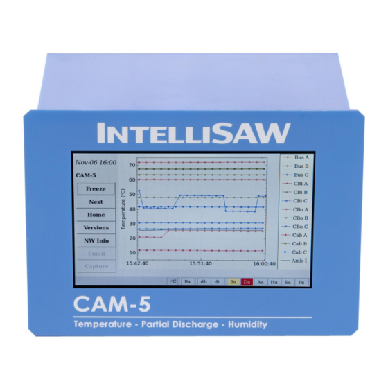
The data points are grouped in sets of three and dT is based on these groups. The data fields are fixed groups based on the data device’s (Reader or CAM-5 internal) physical Modbus registers as shown in the table below. The registers are configured using the IntelliSAW Configuration Tool. Only configured registers which read with values other than error codes will show on the HMI. - Page 43 User Manual May 2018 910.00382.0001 4.2.2.2 Graphical Data Screen The temperature sensor data can also be displayed as a graphical trend. The legend shows all available sensors (up to 12) and 1 ambient temperature sensor. The graph only displays data for enabled registers in the Home Screen.
-
Page 44: Humidity And Ambient Temperature
User Manual 910.00382.0001 May 2018 4.2.3 Humidity and Ambient Temperature 4.2.3.1 Numerical Data Screen CAM monitoring units support up to 8 humidity sensors – e.g. for bus duct monitoring between generators and transformers. The ambient temperature, relative humidity, and dew point are displayed. The ambient sensors are displayed sequentially based on their address (starting with address 0) when configured with the CAM Display Tool. - Page 45 User Manual May 2018 910.00382.0001 4.2.3.2 Graphical Data The ambient temperature / humidity sensor data can also be displayed in a graphical form. The legend shows all available sensor data (up to 8). Figure 28: Ambient Temperature and Humidity Graph Example Notes: ➢...
-
Page 46: Partial Discharge
May 2018 4.2.4 Partial Discharge IntelliSAW monitoring units include specific hardware and an algorithm for analyzing ultra-high frequency (UHF) radio emissions to detect and quantify the signatures of symmetric and asymmetric discharges that are synchronous with the power line frequency, while distinguishing them from other modulated UHF emissions that come from non-discharge related noise sources. - Page 47 User Manual May 2018 910.00382.0001 affect the summary value if the enabled or disabled band is the highest. This data point in the Modbus registers may be used for trending. 4.2.4.1.2.4 Partial Discharge – Phi (φ) PD-Phi (PDφ) is the PD change rate for one antenna port over the enabled bands. The enabling / disabling of frequency bands will affect the summary value if the enabled or disabled band is the highest.
- Page 48 May 2018 4.2.4.2 PD Monitoring Units The IntelliSAW system measures the integrated (cumulative) discharge over a power cycle with a relative scale approximately related to pico-coulombs (pC) cumulative / power cycle. The MODBUS registers are scaled by 10 with counts of 1 – 65534 representing approximately 10 – 655,340 pC cumulative (but non- linear and un-calibrated by default).
- Page 49 User Manual May 2018 910.00382.0001 4.2.4.4 PD / SD Summary: Graphical Data The PD / SD data can also be displayed in a graphical form. There is a unique page for each port that has been configured for PD monitoring. The data shows instantaneous values along with short and long- term exponential weighted averages (α...
-
Page 50: Hmi Configuration
May 2018 Section 5 HMI Configuration The CAM-5 HMI configuration settings are stored in an XML file format and will need to be loaded onto the unit. Please refer to the (910.00384.0001) IntelliSAW CAM Display Tool User Manual for detailed... -
Page 51: Measurement Configuration & Sensor Installation
Sensor Installation 6.1 Measurement Configuration If the CAM-5 has internal measurements (temp, PD, humidity), it will require measurement configuration for the associated installed sensors. Configuration is performed through the USB mini port and uses the IntelliSAW Configuration Tool. Details are not discussed here, please refer to the (910.00160.0001) IntelliSAW Installation Tool User Manual for detailed instructions. -
Page 52: Sensor Installation
User Manual 910.00382.0001 May 2018 6.2 Sensor Installation This manual does not cover specific sensor installation. Please reference the (910.00379.001) IntelliSAW Sensor Installation Manual for more details. -
Page 53: Scada System Integration
The CAM-5 treats holding and input registers identically; however, HOLDING registers are the preferred approach. Modbus-RTU payloads always begin with the address and a function code (FC). The CAM-5 supports the following Modbus function codes, as shown in the following table:... -
Page 54: Modbus Registers
User Manual 910.00382.0001 May 2018 7.1.2 MODBUS REGISTERS Register Description Type Scale Error Code temp 1 signed 16 -500 1675 0.1 C 0x8000 temp 2 signed 16 -500 1675 0.1 C 0x8000 temp 3 signed 16 -500 1675 0.1 C 0x8000 temp 4 signed 16... - Page 55 User Manual May 2018 910.00382.0001 surface 1 unsigned 16 65534 10 "pC" 0xFFFF internal 1 unsigned 16 65534 10 "pC" 0xFFFF noise 2 unsigned 16 65534 10 "pC" 0xFFFF surface 2 unsigned 16 65534 10 "pC" 0xFFFF internal 2 unsigned 16 65534 10 "pC"...
- Page 56 User Manual 910.00382.0001 May 2018 Alpha SD 1 unsigned 16 65534 10 "pC" 0xFFFF Alpha SD 2 unsigned 16 65534 10 "pC" 0xFFFF Alpha SD 3 unsigned 16 65534 10 "pC" 0xFFFF unsigned 16 65534 10 "pC" 0xFFFF Alpha SD 4 Alpha PD 1 unsigned 16 65534...
-
Page 57: Dnp3
910.00382.0001 7.2 DNP3 Up to 10 readers can be bussed together via RS485 to a CAM-5 for displaying and datalogging; this is 9 units if the CAM-5 is also being used for monitoring. The CAM-5 supports DNP3 communications (serial or TCP) and will connect to the SCADA system. -
Page 58: Dnp3 Flags
Communication Lost: Is set when the CAM-5 loses communications to the slave device. Local Forced: Set when communication is lost and values are forced in CAM-5 to Error Values. Remote Forced: Set when communication is OK but the values received in CAM-5 are Error Values. -
Page 59: Mapping Of Modbus To Iec61850
User Manual May 2018 910.00382.0001 7.3.2 Mapping of Modbus to IEC61850 Register Description IEC61850 Mapping Mapped ID of the Modbus Reader CAM5_RdrNN/DevGGIO01$ST$IntIn1$stVal temp 1 CAM5_RdrNN/TmpTTMP01$MX$TmpSv$instMag$f temp 2 CAM5_RdrNN/TmpTTMP02$MX$TmpSv$instMag$f temp 3 CAM5_RdrNN/TmpTTMP03$MX$TmpSv$instMag$f temp 4 CAM5_RdrNN/TmpTTMP04$MX$TmpSv$instMag$f temp 5 CAM5_RdrNN/TmpTTMP05$MX$TmpSv$instMag$f temp 6 CAM5_RdrNN/TmpTTMP06$MX$TmpSv$instMag$f temp 7 CAM5_RdrNN/TmpTTMP07$MX$TmpSv$instMag$f temp 8... - Page 60 User Manual 910.00382.0001 May 2018 internal 1 noise 2 surface 2 internal 2 noise 3 surface 3 internal 3 noise 4 surface 4 internal 4 noise 5 surface 5 internal 5 noise 6 surface 6 internal 6 noise 7 surface 7 internal 7 noise 8 surface 8...
-
Page 61: Mapping Of Digital Output To Iec61850
User Manual May 2018 910.00382.0001 Alpha SD 3 CAM5_RdrNN/SdaSPDC03$MX$UhfPaDsch$mag$f Alpha SD 4 CAM5_RdrNN/SdaSPDC04$MX$UhfPaDsch$mag$f Alpha PD 1 CAM5_RdrNN/PdaSPDC01$MX$UhfPaDsch$mag$f Alpha PD 2 CAM5_RdrNN/PdaSPDC02$MX$UhfPaDsch$mag$f Alpha PD 3 CAM5_RdrNN/PdaSPDC03$MX$UhfPaDsch$mag$f Alpha PD 4 CAM5_RdrNN/PdaSPDC04$MX$UhfPaDsch$mag$f Beta SD 1 CAM5_RdrNN/SdbSPDC01$MX$UhfPaDsch$mag$f Beta SD 2 CAM5_RdrNN/SdbSPDC02$MX$UhfPaDsch$mag$f Beta SD 3 CAM5_RdrNN/SdbSPDC03$MX$UhfPaDsch$mag$f Beta SD 4 CAM5_RdrNN/SdbSPDC04$MX$UhfPaDsch$mag$f... -
Page 62: Specifications
RF Interrogation Distance Up to 1.75 m ≤ 160 mSec RF Interrogation Time Partial Discharge Number of Channels Sensor Type IntelliSAW TPD CAM Air Interfaces Measurement Method Band-pass Ultra-High Frequency (UHF) • (270 – 330 MHz) 300MHz • (550 – 650 MHz) - Page 63 1200 to 38400 baud Data Protocol Modbus RTU Master Response Time 500 ms Supported Devices IntelliSAW IRM readers (up to 10 devices; baud rate dependent) Optional RS485 (SCADA) Port 2-Wire (half-duplex) Data Bus Baud Rate 1200 to 38400 baud •...
- Page 64 Measurement Configuration (CNFG) Port USB 2.0 Mini-B; Windows COM port with FTDI drivers, 115200 baud. Data Protocols IntelliSAW Native Protocol Protection Type 1 (protected area); light industrial protection, configuration only Extended Memory (USB) Port USB 2.0 Type A host Extended Memory –...
- Page 65 User Manual May 2018 910.00382.0001 Operating Power AC input 100 to 250V AC 50 / 60 Hz DC input 120 to 250V DC (functional, no FCC or UL tests) Power Consumption Physical / Environmental Resistive Touch Panel (5” / 800 x 480 resolution) Body: 143.6 mm W x 100.25 mm H x 101.6 mm D Dimensions:...
-
Page 66: Product Certifications
User Manual 910.00382.0001 May 2018 Section 9 Product Certifications 9.1 Compliance Testing FCC Part 15 Radiated Emissions FCC Part 15.231, ANSI C63.4, and IEC Radiated Emissions 61000-6-4 Class A AC Mains Conducted Emissions Conducted Emissions (FCC Part 15 Subpart B: 09/2017, FCC 15.231: 09/2017, IEC 61000-6-4: 02/2011) UL / cUL / IEC 61010-1 Safety Requirements for Electrical Equipment for Measurement, Control, and... -
Page 67: Wireless Certifications
East, and Africa, the rules are similar to the EU EMC Directive. 9.2.2 Approved Antennas The CAM-5 RF module has been approved to operate with the Air Interface (antenna) types listed below with the maximum permissible gain indicated. Air Interface types not included in this list, having a gain greater than the maximum gain indicated for that type, are strictly prohibited for use with this device under FCC or IC approvals. -
Page 68: Federal Communications Commission (Fcc)
1. Metal enclosures described in the IEEE/ANSI Std C37.20, or UL and NEMA specifications derived from Std C37.20, as indicated in KDB 550099. a. The CAM-5 HMI is not required to be in such an enclosure since the Air Interface is wired away from the host. - Page 69 L’appareil doit accepter tout brouillage radioélectrique reçu, y compris le brouillage qui pourrait provoquer le fonctionnement non désiré. Les changements ou les modifications apportés à l'équipement qui n'est pas expressément approuvé par IntelliSAW pourraient annuler l'autorité de l'utilisateur à utiliser cet équipement.
-
Page 70: Contact
User Manual 910.00382.0001 May 2018 Contact Head Office IntelliSAW – ALTANOVA GROUP Rosemount Inc. 100 Burtt Road, Suite 201 Andover, MA 01810 contact@intellisaw.com +1-978-409-1534 www.altanova-group.com Regional Distributors: Visit www.altanova-group.com for sales channel partners. The contents of this publication are presented for information purposes only, and while effort...
Need help?
Do you have a question about the CAM-5 and is the answer not in the manual?
Questions and answers