Advertisement
Table of Contents
- 1 Table of Contents
- 2 Important Safety Instructions
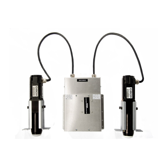
- 3 1- D-BOX 4250I/4400I, 3 Axis Actuators System Overview
- 4 2- D-BOX 4250I/4400I System Dimensions and Setup
- 5 3- Positioning the Components
- 6 4- Positioning the Actuators (Bottom View of Seating)
- 7 5- Arm Rest Mounting Hole Dimensions
- 8 6- Setting up the Actuators in the Seat
- 9 7- Connecting the Actuators to the ACM (Actuator Control Module)
- 10 8- D-BOX 4250I/4400I Electrical Diagram
- 11 9- Pictures of D-BOX Installation (in a Loveseat)
- 12 Appendix 1 - Installation of the ACM Bracket
- Download this manual
Advertisement
Table of Contents

Related Manuals for D-Box 4250i


Summary of Contents for D-Box 4250i
- Page 1 4250i/4400i ACTUATORS (4 actuators, 3 axis system) INSTALLATION GUIDE Technical Support : 1-888-442-3269 ext. 264 Fax : 450-442-3230 E-mail : techsupport@d-box.com Visit us at: www.d-box.com 152-914-0001-EN2...
-
Page 2: Table Of Contents
9- Pictures of D-BOX installation (in a loveseat) Appendix 1 – Installation of the ACM bracket The 4250i may be installed in a single seat and loveseat only. The 4400i may be installed in a single seat, loveseat and 3 seats sofa. -
Page 3: Important Safety Instructions
IMPORTANT SAFETY INSTRUCTIONS Read these instructions. Keep these instructions. Heed all warnings. Follow all instructions. Do not use this apparatus near water. Clean only with dry cloth. Do not block any ventilation openings. Install in accordance with the manufacturer's instructions. Do not install near any heat sources such as radiators, heat registers, stoves, or other apparatus (including amplifiers) that produce heat. -
Page 4: 1- D-Box 4250I/4400I, 3 Axis Actuators System Overview
1- D-BOX 4250i/4400i, 3 axis actuators system overview The D-BOX 4250i/4400i actuators system is designed to be installed into the armrest of qualified home theater seating. When properly installed, the system will give you a three (3) axis motion simulator designed for the home entertainment. - Page 5 The D-BOX 4250i/4400i, 3 axis motion system consists of: Description Quantity ACM unit (Actuator Control Module) Actuator (max. capacity 250 lbs each 4250i and 400 lbs each 4400i) Power Cable, 6 feet (000-090-0010-Z00) Single Cup, Aluminum (810-0002) Screw, Bolt, Hex, Cap, 1/4-20 X 3/4, Black (100-0551))
- Page 6 ACM together (in daisy chain and One (1) 50’ shielded cat-5 cable is supplied to connect the ACM unit to the appropriate Motion Controller port (Kinelink port A to D). Below you will find the dimensions of the 4250i/4400i actuators and the ACM unit. D-BOX 4250i/4400i actuators dimensions (.75” Bracket)
-
Page 7: 3- Positioning The Components
3- Positioning the components The D-BOX 4250i/4400i actuators have been designed to be installed into armrest of qualified home theater seating. Each Actuator must be inserted into the armrest hole especially made for that purpose. The ACM unit can be installed either on the back wood panel or into the armrest depending on mounting clearance. -
Page 8: 4- Positioning The Actuators (Bottom View Of Seating)
4- Positioning the actuators (Bottom view of seating) Each actuator should be mounted at the bottom of each armrest. For that purpose an actuator mounting hole and an actuator cable access hole should be provided. See drawing below for more details; Typical Loveseat armrest Installation (bottom view) 8 of 18... -
Page 9: 5- Arm Rest Mounting Hole Dimensions
5- Arm Rest mounting hole dimensions In the drawings below you will find the dimensions of the hole needed to mount the actuators and be able to screw it in place using four (4) 1/4-20 screws. You will also find the dimensions of the cutout hole for the actuator’s cable harness. -
Page 10: 7- Connecting The Actuators To The Acm (Actuator Control Module)
7- Connecting the actuators to the ACM (Actuator Control Module) IMPORTANT NOTICE : Before doing any connection into the ACM unit make sure there is no power by detaching the A/C cord. There is high voltage inside the ACM unit, and only service qualified technician are allowed to do the connections. - Page 11 Making connections into the ACM unit D. After both actuator’s metal doors have been properly secured to the housing, connect the motor and the encoder connector of both actuators (as shown in drawing below). You should hear a click when the connector is fully inserted. Finally, assemble and secure the access cover, there is one (1) screw on each side and two (2) screws on the rear.
-
Page 12: 8- D-Box 4250I/4400I Electrical Diagram
8- D-BOX 4250i/4400i Electrical diagramm Note: Each time you will power-up the motion seat you will hear the motors locking themselves up. This usually takes a few seconds unless the piston of either actuator has not been pulled in completely at the last shutdown. -
Page 13: 9- Pictures Of D-Box Installation (In A Loveseat)
9- Pictures of D-BOX installation (in a loveseat) Photos below are of the 2250i/2400i but are very similar to the 4250i/4400i installation, the main differences are two ACM units (left and right) instead of one ACM unit and one front actuator instead of front pivot. - Page 14 Pictures of D-BOX installation (in a loveseat) NOTE: Cables must be positioned so they won’t interfere with the recliner’s mechanism. 14 of 18...
- Page 15 Pictures of D-BOX installation (in a loveseat) NOTE: Cables must be positioned so they won’t interfere with the recliner’s mechanism. 15 of 18...
- Page 16 Pictures of D-BOX installation (in a single electrical reclining seat) NOTE: Cables must be positioned so they won’t interfere with the recliner’s mechanism. 16 of 18...
- Page 17 Pictures of D-BOX installation (in a single electrical reclining seat) 17 of 18...
-
Page 18: Appendix 1 - Installation Of The Acm Bracket
Appendix 1 Installation of the ACM bracket 18 of 18...
Need help?
Do you have a question about the 4250i and is the answer not in the manual?
Questions and answers
Hello, I purchased 4 gen 5 4250 actuators from a company called Trak Racer. Each actuator has a diagram showing the position they should be installed however, none of the diagrams I have show a mark indicating where they should be properly placed. Does it matter or am I in trouble. Without a mark on any of the diagrams I have no idea where to install them. I am using them for a race simulation cockpit so I need to place them front left/right and back left/right. Lastly, I noticed each actuator has a voltage switch (120v and 230v). I live in the US so I need them on 120v however, I'm not sure which way the switch should be flipped to choose the correct voltage. Can you send me an image or explanation so I know that I have the voltage switch on the correct (120v) setting. Thanks for your time.
To install the D-Box 4250i actuators in a race simulation cockpit:
1. Position the Actuators: Place the four actuators in their designated positions:
- Front Right: Port A (D)
- Front Left: Port B (G)
- Rear Left: Port C (J)
- Rear Right: Port D (M)
2. Mounting:
- Attach the actuators to the rig using mounting brackets.
- Secure them with screws to ensure stability.
- Ensure the actuators are aligned correctly for proper motion feedback.
3. Connection:
- Connect the actuators to the Actuator Control Module (ACM) using Cat 5 cables.
- Ensure each actuator is plugged into its corresponding port.
4. Configuration:
- In the software, select four actuators and enable roll, pitch, and heave.
- Apply the configuration and wait for the system to load.
To set the voltage switch to 120V:
- Locate the voltage selector at the bottom of the control electronics.
- Switch it to 120V if using in regions with 120V power supply (e.g., North America).
This answer is automatically generated