Table of Contents
Advertisement
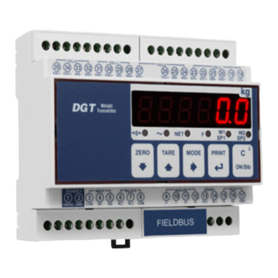
DGT4
Digital weight transmitter with 4 channels
For DGT4 with firmware release minimum 08.03
www.diniargeo.com
USER MANUAL
CE LL 2
CE LL 3
26
27
CE LL 4
28
29
30
31
EX C+
32
33
34
EX C-
SIG +
35
SIG -
EX C+
EX C-
SIG +
SIG -
EX C+
EX C-
RE LA YS
9 10 11
INP UT
8
PO WE R
7
6
5
4
I+
3
2
CO M
1
RL 2
RL 1
IN2
IN1
CO M
+24 Vd c GN D
CE LL 1
18
21 20 19
24 23 22
SIG +
25
SIG -
SE N- SE N+
EX C+
EX C-
SIG +
SIG -
RS 232
RS 485
16 17
AN AL OG
15
14
13
12
GN D
RX
TX
B(- )
A(+ )
V-
V+
I-
ENGLISH
Advertisement
Table of Contents

Related Manuals for Dini Argeo DGT4


Summary of Contents for Dini Argeo DGT4
- Page 1 AN AL OG RE LA YS 9 10 11 GN D INP UT B(- ) A(+ ) PO WE R CO M RL 2 RL 1 CO M +24 Vd c GN D For DGT4 with firmware release minimum 08.03 www.diniargeo.com...
-
Page 3: Table Of Contents
Access to the menu and saving the changes 23 Function of the keys in the menu 24 Block diagram of the menu Mode of use of the DGT4 26 On / Off 27 Theoretical calibration 28 ... - Page 4 Manual calibration 35 Manual calibration 35 Quick zero calibration (pre-tare zeroing) 35 Filter and stability 36 36 Filter adjustment 36 Stability detection sensitivity 37 Display updating frequency Gravity 37 Zeroing parameters 38 ...
- Page 5 Analog output configuration 46 Serial communication configuration 48 48 Selection of the PC serial port Configuration of the printer port (COM.PRN) 49 49 Transmission mode 50 Baud rate, parity, data bits, stop bits 50 Printer power on mode ...
- Page 6 TECH_MAN_ENG_DGT4_V8...
-
Page 7: Introduction
Thank you for purchasing a DINI ARGEO product. This manual contains all the instructions for a correct installation and commissioning of the DGT4 4-channel digital weight transmitter. While thanking you for purchasing this product, we would like to draw your attention to some aspects of this manual. -
Page 8: Transmitter Installation
Transmitter installation Installation requirements Observe the following conditions for correct installation of the transmitter and of the load receiver: • Flat, level support surface. • Stability and absence of vibrations. • Absence of aggressive dusts and vapours. • Absence of draughts. •... -
Page 9: Electrical Precautions
Electrical precautions • Use a regulated mains supply within ± 10% of the rated voltage. • The electrical protections (fuses, etc.) are the responsibility of the installer. • Observe the recommended minimum distances between cables of different categories (see table on page 10). •... - Page 10 RECOMMENDED DISTANCES AND CABLE CLASSIFICATION Category I Category II Category III Category IV ≥ 100 mm ≥ 200 mm ≥ 500 mm Distance ≥ 100 mm ≥ 500 mm ≥ 500 mm Fieldbus, LAN network (PROFIBUS, Ethernet, Devicenet...). Shielded data cables DC supply cables with (RS232...).
-
Page 11: Earthing Of The System
Earthing of the system For correct earthing and optimal system operation, the load cells, junction box, if any, and weighing structure must be earthed. LOAD CELLS AND JUNCTION BOX The connection must be made by connecting the earth cables to the earth bar (cables that must have a cross-section of at least 16 mm finally, connect the earth bar to the earth post with a cable having a cross-section of at least 50 mm EXAMPLES: •... - Page 12 EXAMPLE OF EARTHING OF A WEIGHBRIDGE Weight transmitter Junction box placed on the side wall of the pit Load cell Weighbridge Earth cables Ø 8 - sec. 50 mm Ø 11.3 - sec. 100 mm Drilled copper plate positioned on the side wall Weighbridge Earth post posi- Load cell bypass jumper...
- Page 13 EXAMPLE OF EARTHING OF A SILO Protective earth bypass for the load cell Load cell TECH_MAN_ENG_DGT4_V8...
-
Page 14: Technical Features
DGT4: 100 mA at 12 V / 70 mA at 24 V (2 W); (without load cells) DGT4AN: 185 mA at 12 V / 90 mA at 24 V (2.5 W); DGT4 with fieldbus: 410 mA at 12 V; 220 mA at 24 V (5 W). OPERATING TEMPERATURE From -15°C to +40°C. -
Page 15: Load Cell Installation
Load cell installation After carrying out the instructions for the platform or load receiver, the shielded cable from the cell(s) must be properly connected to the terminal block(s) of the transmitter (from CELL1 to CELL4; see section “Wiring diagrams”). The transmitter has one channel (CELL1) for 6-wire connection to load cells (using the SENSE), while for the remaining channels (CELL2, CELL3 CELL4 CELL2... -
Page 16: Wiring Diagrams
Wiring diagrams DGT4 35 34 33 32 31 30 29 28 27 26 25 24 23 22 21 20 19 18 LOAD CELL 4 LOAD CELL 3 LOAD CELL 2 LOAD CELL 1 Internal use RS485 RS232 11 12 13 14... -
Page 17: Dgt4An
DGT4AN 35 34 35 34 33 32 33 32 31 30 31 30 29 28 29 28 27 26 27 26 25 24 25 24 23 22 23 22 21 20 21 20 19 18 19 18 LOAD CELL 4 LOAD CELL 4 LOAD CELL 3 LOAD CELL 3... -
Page 18: Dgt4Pb
DGT4PB 35 34 33 32 31 30 29 28 27 26 25 24 23 22 21 20 19 18 LOAD CELL 4 LOAD CELL 3 LOAD CELL 2 LOAD CELL 1 PROFIBUS PORT Internal use RS232 15 16 17 TECH_MAN_ENG_DGT4_V8... -
Page 19: Dgt4Ethip, Dgt4Ethcat, Dgt4Pronet, Dgt4Modtcp
DGT4ETHIP, DGT4ETHCAT, DGT4PRONET, DGT4MODTCP 35 34 33 32 31 30 29 28 27 26 25 24 23 22 21 20 19 18 LOAD CELL 4 LOAD CELL 3 LOAD CELL 2 LOAD CELL 1 Internal use RS232 15 16 17 TECH_MAN_ENG_DGT4_V8... -
Page 20: Dgt4Canop
DGT4CANOP 35 34 33 32 31 30 29 28 27 26 25 24 23 22 21 20 19 18 LOAD CELL 4 LOAD CELL 3 LOAD CELL 2 LOAD CELL 1 Internal use RS232 15 16 17 TECH_MAN_ENG_DGT4_V8... -
Page 21: Dgt4Devnet
DGT4DEVNET 35 34 33 32 31 30 29 28 27 26 25 24 23 22 21 20 19 18 LOAD CELL 4 LOAD CELL 3 LOAD CELL 2 LOAD CELL 1 Internal use RS232 15 16 17 TECH_MAN_ENG_DGT4_V8... -
Page 22: Display And Function Of The Keys
Display and function of the keys CELL4 CELL3 CELL2 CELL1 24 23 22 21 20 19 EXC- EXC+ SIG- SIG+ EXC- EXC+ SIG- SIG+ EXC- EXC+ SIG- SIG+ EXC- EXC+ SEN- SEN+ SIG- SIG+ POWER INPUT RELAYS... -
Page 23: Advanced Programming Menu
Advanced programming menu The advanced menu contains all the transmitter configuration parameters for the most advanced adjustments. Access to the menu and saving the changes Reboot the transmitter. Press the key when the display shows 888888. HOW TO EXIT THE SETUP AND SAVE CHANGES Press several times, until the display shows “save?”. -
Page 24: Block Diagram Of The Menu
Block diagram of the menu 888888 TYPE Mode of use (page 26). Operating mode (page 44). f.mode funct Reactivating printing (page 52). React CloCk Date and time (page 61). tare Tare (page 41). Zero restore (page 40). rs.zero setup ConfiG nChan Continued on page 25. - Page 25 Full ConfiG setup menuis displayed. Setup ConfiG nChan Number of channels used. Calibration (page 27 / 29 / 31 / 33). Chan Channel to be configured. Calibration (page 29 / 33). Filt.50 Filter (page 37). param stabil auto-0 Zero parameters (page 39). 0-perC 0.traCk div.stb...
-
Page 26: Mode Of Use Of The Dgt4
Mode of use of the DGT4 TYPE dep.Ch Smart junction box mode. 1 scale mode. ind.Ch 4 scale mode. transm Mode 1 “DEP.CH” Allows you to connect the load cells (from 2 to 4) directly and to equalise them. Cell 1... -
Page 27: On / Off
Mode 3 “TRANSM” Allows you to manage up to 4 independent scales. Scale 1 Scale 2 CELL4 CELL3 CELL2 CELL1 24 23 22 21 20 19 EXC- EXC+ SIG- SIG+ EXC- EXC+ SIG- SIG+ EXC- EXC+ SIG- SIG+ EXC- EXC+ SEN- SEN+ SIG- SIG+... -
Page 28: Theoretical Calibration
Theoretical calibration Dependent channels 888888 TYPE dep.Ch Setup ConfiG nChan DECI Calib U.M. RANGE1 theo.CA Cel.sen Cel.Cap Dead.ld kno.wGt CALIBRATION PROCEDURE: Select mode of use dep.Ch. Set the number of channels used (from 1 to 4). Set the calibration parameters: = Number of decimals. -
Page 29: Independent Channels / Transm
Independent channels / transm 888888 TYPE Ind.Ch Setup ConfiG nChan Chan Calib DECI U.M. RANGE1 theo.CA Cel.sen Cel.Cap Dead.ld kno.wGt CALIBRATION PROCEDURE: Select mode of use ind.Ch. Set the number of connected scales (from 1 to 4). Select the scale to be calibrated (from 1 to 4). Set the calibration parameters: = Number of decimals. -
Page 30: Calibration With Sample Weights
Calibration with sample weights Dependent channels (with digital equalisation) 888888 TYPE dep.Ch Setup ConfiG nChan Calib DECI U.M. RANGE1 Calib.p equal n tp tp 0 ddt1 tp 1 ddt2 tp 2 ddt3 tp 3 CALIBRATION PROCEDURE: Select mode of use dep.Ch. Set the number of connected scales (from 1 to 4). - Page 31 Acquire the calibration points: Display View: Display View: Display View: n tP tp 0 press Press and select the number of calibration Unload the scale. points using the keys (from 1 to 3). To acquire the zero point press To confirm press Display View: Display View: Display View:...
-
Page 32: Independent Channels / Transm
Independent channels / transm 888888 TYPE ind.Ch Setup ConfiG nChan nChan Calib DECI U.M. RANGE1 equal Calib.p n tp tp 0 ddt1 tp 1 ddt2 tp 2 ddt3 tp 3 CALIBRATION PROCEDURE: Select mode of use ind.Ch. Set the number of connected scales (from 1 to 4). Select the scale to be calibrated (from 1 to 4). - Page 33 Acquire the calibration points: Display View: Display View: Display View: n tP tp 0 press Press and select the number of calibration Unload the scale. points using the keys (from 1 to 3). To acquire the zero point press To confirm press Display View: Display View: Display View:...
-
Page 34: Equalisation
Equalisation If the dependent channel mode has been set, you can improve the accuracy of the system by digitally equalising the connected cells. 888888 dep.Ch TYPE Setup ConfiG Calib deCi Visible only if Calib.p equal reset? type = Dep.Ch Display View: Display View: Display View: eq 0... -
Page 35: Manual Calibration
Manual calibration Manual calibration 888888 TYPE Setup ConfiG Calib deCi man.Cal If you know the number of ADC converter points for a known weight (for example if you want to copy the calibration from one transmitter to another) the calibration points can be entered manually: The display showsmod.pnt, proceed by pressing the key. -
Page 36: Filter And Stability
Filter and stability Filter adjustment 888888 TYPE Setup ConfiG Param Stabil Filter Response time (ms) Updating frequency Filter Response time (ms) Updating frequency (Hz) (Hz) 1230 h.r.0 flt 2 1435 h.r.1 flt 3 1840 h.r.2 f.f.50.1 2050 h.r.3 f.f.50.2 3280 h.r.4 f.f.50.3 4100... -
Page 37: Display Updating Frequency
Display updating frequency Additional filter that acts only by displaying the weight, thus increasing its stability. Useful in particular applications where you want to make the weight more stable in the eyes of the operator. 888888 TYPE This parameter does not affect the actual speed and stability of the weight (set via the filter). -
Page 38: Zeroing Parameters
Zeroing parameters 888888 TYPE Setup ConfiG param stabil % auto-zeroing on ignition. auto.0 % manual zeroing. 0-perC Zero tracking. 0.traCk Auto-zeroing on ignition auto.0 disab Disabled. enab C.perC Enabled, enter in C.PERC the % value of the capacity. from 0 to 50%. from 0 to 10%. -
Page 39: Restoring Zero
Restoring zero 888888 Type F.mode funCt DISAB Restoring zero disabled. rs.zero Restoring zero enabled. ENAB • If auto.0 = disab: The last zeroing in the memory before turning off the power is always restored. • If auto.0 = enab / CyCle: The last zeroing in the memory before turning off the power is restored only if the auto-zeroing fails. -
Page 40: Tare Functions And Parameters
Tare functions and parameters Tare mode 888888 Type F.mode funCt Tare blocked. When the gross weight drops to 0, the tare remains loCk tare engaged. Tare unlocked. When the gross weight drops to 0, the tare is cleared. unloCK Disab Tare disabled. -
Page 41: Alibi Memory
Alibi memory The alibi memory allows you to store the weight values transmitted to the computer for further processing and/or data integration. The stored values can then be retrieved from the PC port or directly on the display of the transmitter for later checking. Enabling the alibi memory 888888 Type... -
Page 42: Reading The Alibi Memory
Reading the alibi memory FROM THE TRANSMITTER (MANUAL) By pressing the key you can read a saved weight: you will be asked to enter the rewrite number “rew.id” (from 0 to 255) and the ID number “id” (from 0 to 131072). The weighing data are shown. -
Page 43: Use Functions
Use functions 888888 Type F.mode funCt viss peak Conver alibi none High resolution Weight display in high resolution (x10). Press the key to activate or deactivate the function. viss When the weight is displayed in high resolution, the indicator light is lit. -
Page 44: Input Configuration
Input configuration The indicator has 2 configurable inputs (bidirectional optocouplers). 888888 TYPE Setup ConfiG inputs inp.01 Such as inp.02 ( = zero). inp.02 NoNE No function. key. zero tare key. key. mode print key. key. Reboots the transmitter. Disable keypad (and re-enable). Dis.key INPUT CONNECTION: The input is activated when there is a potential difference between terminals 4 - 5 (IN1 and IN2) -
Page 45: Output Configuration
Output configuration The indicator has 2 programmable outputs (photomosfet). 888888 TYPE Setup ConfiG output out.01 Such as out.02. out.02 funC No function. 0 none 1 Gros Setpoint on gross weight. Setpoint on net weight. 2 net 4 Gro.0 Gross weight on zero. 5 net.0 Net weight on zero. -
Page 46: Analog Output Configuration
Analog output configuration The DGT4AN model has an analog output in voltage (0 - 5 / 0 - 10 Vdc) or current (4 - 20 / 0 - 20 mA). 888888 TYPE Setup ConfiG Selection of the scale associated with the analog output. an.out Chan Visible only if type = ind.Ch / transm and Chan ≥... - Page 47 CALIBRATION PROCEDURE: Connect a multimeter to the transmitter. Increase or decrease the value to Press to update the output value Go to the parameter to be changed reach the desired output. on the multimeter. min) and set an max, approximate value. 100 D/A points ~ 0.015 V / 0.035 mA 1000 D/A points ~ 0.15 V / 0.34 mA 10000 D/A points ~ 1.57 V / 3.42 mA...
-
Page 48: Serial Communication Configuration
Serial communication configuration The transmitter has 2 serial ports (232 and 485) that can be used indiscriminately to communicate: • In bidirectional mode with the PC / PLC (“PC” port); • In one-directional mode with the PC, thermal printer, repeater (“PRN” port); It is necessary to choose which port to use as PC and, consequently, which one to use as PRN. -
Page 49: Configuration Of The Printer Port (Com.prn)
Transmission not enabled. prpC.hk Transmission of the weight value when the key is pressed. Transmission of the weight to DINI ARGEO 6-digit repeater. repe.6 prPC.ex Extended string transmission when the key is pressed. prpC.st Standard string transmission when the key is pressed. -
Page 50: Baud Rate, Parity, Data Bits, Stop Bits
Baud rate, parity, data bits, stop bits 9600 baud.pr 4800 2400 1200 115200 57600 38400 19200 prty.pr none No parity, 8 data bits, 1 stop bit. Even. even Odd. 8 bits. bit.pr 7 bits. stop.pr 1 stop bits. 2 stop bits. Printer power on mode It is possible to set the way the printer is turned on: pwr.ext... -
Page 51: Reactivation Of Printing
Data bits. stop Stop bits. Transmission mode Transmission on demand. pCmode onde Transmission of the weight on DINI ARGEO 6-digit repeater. repe.6 Standard string transmission when the key is pressed. Prin.st Extended string transmission when the key is pressed. prin.ex Transmission with 485 protocol (enter the 485 address of the transmitter). -
Page 52: Baud Rate, Parity, Data Bits, Stop Bits
Baud rate, parity, data bits, stop bits baud 9600 4800 2400 1200 115200 57600 38400 19200 parity none No parity, 8 data bits, 1 stop bit. even Even. Odd. 8 bits. 7 bits. stop 1 stop bits. 2 stop bits. MENU ACCESS: SAVING THE PARAMETERS: Complete menu on pages... -
Page 53: Communication Protocols
Communication protocols Standard string [01]ST,GS, 0.0,kg<CR><LF> Where: Transmitter code 485 (2 characters), only if communication mode 485 is enabled Scale status (2 characters): US - Unstable weight ST - Stable weight OL - Weight overload (out of range) UL - Weight underload (out of range) Character ASCII 044 Type of weight data (2 characters) GS - Gross... -
Page 54: Multi-Scale String
Multi-scale string If type = transm [01]ST, 612,kg,ST, 61.4, t,ST, 6.17, g,ST, 0.617,lb Where: Transmitter code 485 (2 characters), only if communication mode 485 is enabled Scale 1 status (2 characters): US - Unstable weight ST - Stable weight VL - Microvolts RZ - Converter points Character ASCII 044 Scale 1 weight (8 characters including the decimal point) -
Page 55: Serial Commands
Serial commands By selecting the PC port on demand mode (onde), you can communicate with the transmitter via serial commands. For each command received, the transmitter emits a string containing the response (refer to the command description) or one of the following signals: Command sent when sending a correct command. - Page 56 PRESSING A KEY Format Key code. To simulate pressing a key, you must send the KEYP and KEYR commands in succession. If more than 1.5 s pass after the KEYP command is sent, the transmitter will execute the function associated with Where prolonged pressing of the key.
- Page 57 READING OF MICROVOLTS READING OF CONVERTER POINTS Format Format Response Response Standard string. Standard string. INITIALISING ALIBI MEMORY WEIGHT READING WITH DATE AND TIME Format Format Response ALDLOK / ALDLNO Response Extended string. READING A WEIGHING OPERATION IN THE ALIBI MEMORY Format Response Scale number.
-
Page 58: Diagnostics
Diagnostics 888888 TYPE diaG Cells / converter test Display of the µV related to the weight on the scale. adC.uv Use the keys to display the different channels (in dep.Ch mode the sum is also visible). For correct operation, the value of the µV of each channel must be less than 30000 with a weight equal to the maximum capacity. This value must be stable, and increase if a load is applied to the cell. -
Page 59: Serial Ports
Serial ports Bridge between serial ports (for manufacturer’s use). CTS signal Checking the CTS signal of the printer (on) connected to the PRN port. Cts.st. Inputs Checking the status of the inputs: inputs value 0 indicates that the input is disabled, value 1 indicates that the input is enabled. Usethe keys to display the two inputs. -
Page 60: Restoring Factory Settings
Restoring factory settings 888888 TYPE Setup ConfiG defau The transmitter is initialized and the default parameters (indicated by the symbol) are activated. Pressing the display shows “dflt?” confirm further with or exit by pressing another key. The actual activation of the default parameters is performed by saving the settings (save?) while exiting the menu. Date and time setting 888888 TYPE... -
Page 61: Alarms
Alarms Alarm Description Displayed if you try to calibrate a point without first confirming the number of calibration points (n tp). preC Calibration error: unstable weight during point acquisition. er.mot Calibration error: during the acquisition of a calibration point a NULL value was read from the converter. erpnt Error that occurs if the capacity of channel X is not set, or there is an error in the calibration parameters of err.x.1... - Page 62 Notes This publication, part reproduced without written permission from Manufacturer. information this manual based data available time publication; Manufacturer reserves right make changes products time, without notice without incurring penalty. therefore recommend that always check updates. person responsible scale must ensure that safety...
- Page 64 Stamp of the authorized service center HEAD OFFICE Via Della Fisica, 20 41042 Spezzano di Fiorano, Modena - Italy Tel. +39 0536 843418 - Fax +39 0536 843521 SERVICE ASSISTANCE Via Dell’Elettronica, 15 41042 Spezzano di Fiorano, Modena - Italy Tel.
Need help?
Do you have a question about the DGT4 and is the answer not in the manual?
Questions and answers