Table of Contents
Advertisement
Advertisement
Table of Contents

Related Manuals for Deye SUN-3.6K-SG01LP1-EU


Summary of Contents for Deye SUN-3.6K-SG01LP1-EU
- Page 1 Hybrid Inverter User Manual...
-
Page 2: Table Of Contents
Contents 1. Safety Introductions ……………………………………………… 2. Product instructions 01-04 ……………………………………………… 2.1 Product Overview 2.2 Product Size 2.3 Product Features 2.4 Basic System Architecture 3. Installation 05-19 …………………………………………………………… 3.1 Parts list 3.2 Mounting instructions 3.3 Battery connection 3.4 Grid connection and backup load connection 3.5 PV Connection 3.6 CT Connection 3.7 Earth Connection(mandatory) - Page 3 Contents may be periodically updated or revised due to product development. The informa�on in this manual is subject to change without no�ce. The latest manual can be acquired via service@deye.com.cn 1. Safety Introduc�ons · This chapter contains important safety and opera�ng instruc�ons. Read and keep this manual for future reference.
-
Page 4: Product Overview
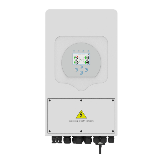
2.1 Product Overview 1: Inverter Indicators 7: DRMs Port 13: Power on/off bu�on 2: LCD display 8: Parallel port 14: DC Switch 3: Func�on Bu�ons 9: Func�on Port 15: PV input with two MPPT 4: Ba�ery input connectors 10: Generator input 16: Ba�ery 5: RS 485 Port 11: Load... -
Page 5: Product Size
2.2 Product Size Inverter Size Moun�ng bracket - 03 -... -
Page 6: Product Features
2.3 Product Features - Self-consump�on and feed-in to the grid. - Auto restart while AC is recovering. - Programmable supply priority for ba�ery or grid. - Programmable mul�ple opera�on modes: On grid, off grid and UPS. - Configurable ba�ery charging current/voltage based on applica�ons by LCD se�ng. - Configurable AC/Solar/Generator Charger priority by LCD se�ng. -
Page 7: Parts List
3. Installa�on 3.1 Parts List Check the equipment before installa�on. Please make sure nothing is damaged in the package. You should have received the items in the following package: Stainless steel an�-collision Hybrid inverter Wall moun�ng bracket x1 bolt M8×80 Stainless steel moun�ng Parallel communica�on L-type Hexagon wrench... - Page 8 3.2 Moun�ng instruc�ons Installa�on Precau�on This Hybrid inverter is designed for outdoor use(IP65), Please make sure the installa�on site meets below condi�ons: · Not in direct sunlight · Not in areas where highly flammable materials are stored. · Not in poten�al explosive areas. ·...
- Page 9 ≥500mm ≥500mm For proper air circula�on to dissipate heat, allow a clearance of approx. 50cm to the side and approx. 50cm above and below the unit. And 100cm to the front. Moun�ng the inverter Remember that this inverter is heavy! Please be careful when li�ing out from the package. Choose the recommend drill head(as shown in below pic) to drill 4 holes on the wall, 52-60mm deep.
- Page 10 Inverter hanging plate installa�on 3.3 Ba�ery connec�on For safe opera�on and compliance, a separate DC over-current protector or disconnect device is required between the ba�ery and the inverter. In some applica�ons, switching devices may not be required but over-current protectors are s�ll required. Refer to the typical amperage in the table below for the required fuse or circuit breaker size.
- Page 11 All wiring must be performed by a professional person. Connec�ng the ba�ery with a suitable cable is important for safe and efficient opera�on of the system. To reduce the risk of injury, refer to Chart 3-2 for recommended cables. Please follow below steps to implement ba�ery connec�on: 1.
- Page 12 3.3.2 Func�on port defini�on DIP Switch Inverter BMS 485 BMS CAN DRMs HM G-V G-S ATS240V parallel_1 parallel_2 RS 485 BMS 485: RS485 port for ba�ery 240V Coil communica�on. Neutral BMS CAN: CAN port for ba�ery Earth Bond Batt Temp communica�on.
- Page 13 3.3.3 Temperature sensor connec�on for lead-acid ba�ery Temp. CT - 11 -...
- Page 14 3.4 Grid connec�on and backup load connec�on · Before connec�ng to grid, please install a separate AC breaker between inverter and grid. Also, it is recommended that installs an AC breaker between backup load and inverter.This will ensure the inverter can be securely disconnected during maintenance and fully protected from over current.
- Page 15 GEN PORT LOAD GRID GEN PORT LOAD GRID - 13 -...
-
Page 16: Pv Connection
Be sure that AC power source is disconnected before a�emp�ng to wire it to the unit. 3. Then, insert AC output wires according to polari�es indicated on the terminal block and �ghten terminal. Be sure to connect corresponding N wires and PE wires to related terminals as well. 4. - Page 17 3.5.1 PV Module Selec�on: When selec�ng proper PV modules, please be sure to consider below parameters: 1) Open circuit Voltage (Voc) of PV modules not exceeds max. PV array open circuit voltage of inverter. 2) Open circuit Voltage (Voc) of PV modules should be higher than min. start voltage. Inverter Model 3.6KW PV Input Voltage...
-
Page 18: Earth Connection(Mandatory)
3.6 Temperature sensor connec�on for lead-acid ba�ery L N PE L N PE L N PE Load Grid Inverter White wire Black wire Grid 3.7 Earth Connec�on(mandatory) Ground cable shall be connected to ground plate on grid side this prevents electric shock. if the original protec�ve conductor fails. -
Page 19: Wiring System For Inverter
3.9 Wiring System for Inverter This diagram is an example for grid systems without special requirements on electrical wiring connec�on. Note: The back-up PE line and earthing bar must be grounded properly and DC Breaker effec�vely. Otherwise the back-up func�on may be abnormal when the grid fails. AC Breaker Load Battery... -
Page 20: Single Phase Parallel Connection Diagram
3.10 Single phase parallel connec�on diagram L wire N wire PE wire Inverter No.3 L N PE L N PE L N PE (slave) BMS 485 BMS CAN DRMs Load Grid Ground parallel_1 parallel_2 RS485 Inverter ④ ① DC Inverter Breaker No.2 ⑤... -
Page 21: Three Phase Parallel Inverter
3.11 Three phase Parallel Inverter - 19 -... -
Page 22: Operation
4. OPERATION 4.1 Power ON/OFF Once the unit has been properly installed and the ba�eries are connected well, simply press On/Off bu�on(located on the le� side of the case) to turn on the unit.When system without ba�ery connected, but connect with either PV or grid, and ON/OFF bu�on is switched off, LCD will s�ll light up(Display will show OFF), In this condi�on, when switch on ON/OFF bu�on and select NO ba�ery, system can s�ll work. -
Page 23: Lcd Display Icons
5. LCD Display Icons 5.1 Main Screen The LCD is touchscreen, below screen shows the overall informa�on of the inverter. 12/18/2020 09:21:00 1.85 0.04 -1.79 0.02 1.The icon in the center of the home screen indicates that the system is Normal opera�on. If it turns into "comm./FXX"... - Page 24 5.1.1 LCD opera�on flow chart Solar Page Solar Graph Grid Page Grid Graph Inverter Page Main Screen Battery Page BMS Page Load Page Load Graph Battery Setting System Work Mode Grid Setting System Setup Gen Port Use Basic Setting Advanced Function Device info - 22 -...
-
Page 25: Solar Power Curve
5.2 Solar Power Curve Solar This is Solar Panel detail page. ③ ① ① Solar Panel Genera�on. Power: 1560W Today=8.0 KWH Voltage, Current, Power for each MPPT. ② ② PV1-V: 286V PV2-V: 45V Total =12.00 KWH ③ Solar Panel energy for Day and Total. PV1-|: 5.5A PV2-|: 0.0A P1: 1559W... -
Page 26: Curve Page-Solar & Load & Grid
Li-BMS Mean Voltage:50.34V Charging Voltage :53.2V Batt Total Current:55.00A Discharging Voltage :47.0V Data Mean Temp :23.5C Charging current :50A Total SOC :38% Discharging current :25A Stand-by Dump Energy:57Ah Details SOC: 36% Data U:50.50V I:-58.02A Li-BMS Power: -2930W Charge Volt Curr Temp Energy Fault... -
Page 27: System Setup Menu
5.4 System Setup Menu System Setup This is System Setup page. System Work Mode Battery Setting Gen Port Grid Setting Basic Advanced Device Info. Setting Function 5.5 Basic Setup Menu Basic Setting Factory Reset: Reset all parameters of the inverter. Lock out all changes: Enable this menu for se�ng Time Syncs Beep... -
Page 28: Battery Setup Menu
5.6 Ba�ery Setup Menu Battery Setting Ba�ery capacity: it tells Deye hybrid inverter to know your ba�ery bank size. Batt Mode Use Ba� V: Use Ba�ery Voltage for all the se�ngs (V). Lithium 400Ah Batt Capacity Batt Use Ba� %: Use Ba�ery SOC for all the se�ngs (%). - Page 29 Battery Setting There are 3 stages of charging the Ba�ery . ① ① ③ Float V Shutdown This is for professional installers, you can keep it 53.6V ② if you do not know. Low Batt Batt Absorption V 57.6V Set3 Restart Shutdown 20%: The inverter will shutdown if the SOC Equalization V...
-
Page 30: System Work Mode Setup Menu
5.7 System Work Mode Setup Menu System Work Mode Work Mode Selling First: This Mode allows hybrid inverter to sell 5000 back any excess power produced by the solar panels to Selling First Max Solar Power the grid. If �me of use is ac�ve, the ba�ery energy also Work Zero Export To Load Solar Sell... - Page 31 Solar Sell: “Solar sell” is for Zero export to load or Zero export to CT: when this item is ac�ve, the surplus energy can be sold back to grid. When it is ac�ve, PV Power source priority usage is as follows: load consump�on and charge ba�ery and feed into grid.
-
Page 32: Grid Setup Menu
5.8 Grid Setup Menu Grid Setting Please select the correct Grid Mode in your local area. Grid Mode General Standard If you are not sure, please choose General Standard. UL1741& IEEE1547 Grid Please select the correct Grid Type in your local area, CPUC RULE21 Set1 otherwise the machine will not work or be damaged. -
Page 33: Generator Port Use Setup Menu
5.9 Generator Port Use Setup Menu GEN PORT USE Generator input rated power: allowed Max. power from diesel generator. Mode GEN connect to grid input: connect the diesel generator to the Generator Input GEN connect to Grid input grid input port. PORT Rated Power Smart Load Output: This mode u�lizes the Gen input connec�on... -
Page 34: Advanced Function Setup Menu
5.10 Advanced Func�on Setup Menu Advanced Function Solar Arc Fault ON: This is only for US. System selfcheck: Disable. this is only for factory. Solar Arc Fault ON Backup Delay Gen Peak-shaving: Enable When the power of the generator exceeds the rated value of it, the inverter will Func Clear Arc_Fault provide the redundant part to ensure that the generator... -
Page 35: Device Info Setup Menu
5.11 Device Info Setup Menu Li-BMS Li-BMS Device Info. This page show Inverter ID, Inverter version and alarm Inverter ID: 1601012001 Flash Charge Charge Volt Volt Curr Curr Temp Temp Energy Energy Fault Fault codes. MAIN:Ver2138 HMI: Ver0302 Volt Volt Curr Curr 50.38V 19.70A... - Page 36 Mode III: With Generator AC cable DC cable Solar Backup Load On-Grid Home Load Grid Battery Generator Mode IV: With Smart-Load AC cable DC cable Solar Backup Load On-Grid Home Load Grid Battery Smart Load Mode V: AC Couple On-Grid+AC couple AC cable DC cable Solar...
-
Page 37: Fault Information And Processing
The 1st priority power of the system is always the PV power, then 2nd and 3rd priority power will be the ba�ery bank or grid according to the se�ngs. The last power backup will be the Generator if it is available. 7. - Page 38 Error code Description Solutions 1. When inverter is in Split phase(120/240Vac) or three-phase GFDI _Relay_Failure system (120/208Vac) system, the backup load port N line needs to connect ground; 2. If the fault still exists, please contact us for help. 1. When the grid type and frequency changed it will report F13; 2.
- Page 39 Error code Description Solutions 1. Check the backup load connected, make sure it is in allowed power range; ACOvercurrent fault 2. If the fault still exists, please contact us for help. No Utility 1. Please confirm grid is lost or not; No AC grid 2.
-
Page 40: Limitation Of Liability
Under the guidance of our company, customers return our products so that our company can provide service of maintenance or replacement of products of the same value. Customers need to pay the necessary freight and other related costs. Any replacement or repair of the product will cover the remaining warranty period of the product. -
Page 41: Datasheet
9. Datasheet Model SUN-3.6K-SG01/03LP1-EU SUN-5K-SG01/03LP1-EU Battery Input Date Ba�ery Type Lead-acid or Li-lon Ba�ery Voltage Range(V) 40-60V Max. Charging Current(A) 120A Max. Discharging Current(A) 120A Charging Curve 3 Stages / Equaliza�on External Temperature Sensor Op�onal Charging Strategy for Li-lon Ba�ery Self-adap�on to BMS PV String Input Data Max. - Page 42 Model SUN-3.6K-SG01/03LP1-EU SUN-5K-SG01/03LP1-EU Certifications and Standards VDE 0126, AS4777, NRS2017, G98, G99, IEC61683, IEC62116, Grid Regula�on IEC61727, RD1699: 2011, XP C15-712-3: 2019-05 Safety Regula�on IEC62109-1, IEC62109-2 EN61000-6-1, EN61000-6-3 General Data Opera�ng Temperature Rande(℃) -25~60℃, >45℃ Dera�ng Cooling Smart cooling Noise(dB) <30 dB Communica�on with BMS RS485;...
- Page 43 10. Appendix I Approved ba�ery brand from Deye 48V Storage INVERTER note Brand Model RS485 or CAN inverter SETUP ● US2000 RS485 ● PYLON ● US2000-PLUS RS485 ● Short line 6&7 B4850 ● at inverter side DYNESS POWERBOX F ●...
-
Page 44: Appendix
11. Appendix II Defini�on of RJ45 Port Pin for BMS RS485 Pin CAN Pin 1 2 3 4 5 6 7 8 RS485B RS485A CANH CANL RS485A RS485B RS485 Port CAN Port - 42 -... -
Page 45: Appendix
12. Appendix III 1. Split Core Current Transformer (CT) dimension: (mm) 2. Seconddary output cable length is 4m. Lead Outside - 43 -... - Page 46 Add: No.26-30, South Yongjiang Road, Beilun, 315806, Ningbo, China Tel: +86 (0) 574 8622 8957 Fax: +86 (0) 574 8622 8852 E-mail: service@deye.com.cn Web: www.deyeinverter.com 502012021 Ver: 2.0, 2020-12...
Need help?
Do you have a question about the SUN-3.6K-SG01LP1-EU and is the answer not in the manual?
Questions and answers