Juniper SRX300 Hardware Manual
Services gateway
Hide thumbs
Also See for SRX300:
- Reference manual (142 pages) ,
- Hardware manual (134 pages) ,
- User manual (128 pages)
Table of Contents
Advertisement
Quick Links
Advertisement
Table of Contents
Troubleshooting

Related Manuals for Juniper SRX300


Summary of Contents for Juniper SRX300
- Page 1 SRX300 Services Gateway Hardware Guide Published 2021-04-21...
- Page 2 END USER LICENSE AGREEMENT The Juniper Networks product that is the subject of this technical documentation consists of (or is intended for use with) Juniper Networks software. Use of such software is subject to the terms and conditions of the End User License Agreement (“EULA”) posted at https://support.juniper.net/support/eula/.
-
Page 3: Table Of Contents
Site Preparation Checklist for the SRX300 Services Gateway | 25 SRX300 Site Guidelines and Requirements | 27 General Site Installation Guidelines for the SRX300 Services Gateway | 28 SRX300 Services Gateway Environmental Specifications | 28 SRX300 Services Gateway Electrical Wiring Guidelines | 29... - Page 4 Powering Off the SRX300 Services Gateway | 51 Connecting the SRX300 to External Devices | 52 Connecting the Dial-Up Modem to the Console Port on the SRX300 Services Gateway | 52 Connecting to the SRX300 Services Gateway CLI Using a Dial-Up Modem | 53...
- Page 5 Troubleshooting the SRX300 | 68 Troubleshooting Resources for the SRX300 Services Gateway Overview | 68 Troubleshooting Chassis and Interface Alarm Messages on the SRX300 Services Gateway | 69 Troubleshooting the Power System on the SRX300 Services Gateway | 70 Using the RESET CONFIG Button | 70...
- Page 6 Product Disposal Warning | 107 Action to Take After an Electrical Accident | 108 General Electrical Safety Guidelines and Warnings | 108 SRX300 Agency Approvals and Compliance Statements | 109 SRX300 Services Gateway Agency Approvals | 109 SRX300 Services Gateway EMC Requirements | 111...
- Page 7 Japan | 111 United States | 112...
-
Page 8: About The Documentation
Use this guide to install hardware and perform initial software configuration, routine maintenance, and troubleshooting for the SRX300 Services Gateway. After completing the installation and basic configuration procedures covered in this guide, refer to the Junos OS documentation for information about further software configuration. -
Page 9: Merging A Full Example
If the example configuration contains the top level of the hierarchy (or multiple hierarchies), the example is a full example. In this case, use the load merge command. If the example configuration does not start at the top level of the hierarchy, the example is a snippet. In this case, use the load merge relative command. -
Page 10: Merging A Snippet
Merging a Snippet To merge a snippet, follow these steps: 1. From the HTML or PDF version of the manual, copy a configuration snippet into a text file, save the file with a name, and copy the file to a directory on your routing platform. For example, copy the following snippet to a file and name the file ex-script-snippet.conf. - Page 11 Table 1: Notice Icons Icon Meaning Description Informational note Indicates important features or instructions. Caution Indicates a situation that might result in loss of data or hardware damage. Warning Alerts you to the risk of personal injury or death. Laser warning Alerts you to the risk of personal injury from a laser.
- Page 12 Table 2: Text and Syntax Conventions (continued) Convention Description Examples Italic text like this Represents variables (options for Configure the machine’s domain which you substitute a value) in name: commands or configuration [edit] statements. root@# set system domain-name domain-name Text like this Represents names of configuration To configure a stub area, include statements, commands, files, and...
-
Page 13: Documentation Feedback
URL or page number, and software version (if applicable). Requesting Technical Support Technical product support is available through the Juniper Networks Technical Assistance Center (JTAC). If you are a customer with an active Juniper Care or Partner Support Services support contract, or are... -
Page 14: Self-Help Online Tools And Resources
JTAC hours of operation—The JTAC centers have resources available 24 hours a day, 7 days a week, 365 days a year. Self-Help Online Tools and Resources For quick and easy problem resolution, Juniper Networks has designed an online self-service portal called the Customer Support Center (CSC) that provides you with the following features: Find CSC offerings: https://www.juniper.net/customers/support/... -
Page 15: Overview
C HAPTER Overview SRX300 Services Gateway Overview | 16 SRX300 Chassis | 17 SRX300 Power System | 22... -
Page 16: Srx300 Services Gateway Overview
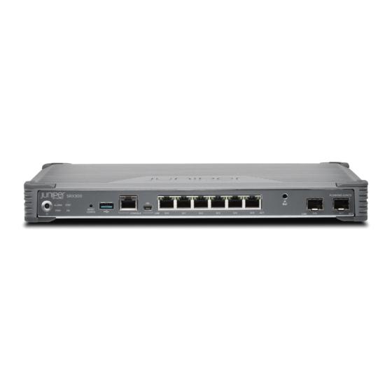
The SRX300 Services Gateway provides firewall support with key features such as IP security (IPsec) VPN and Unified Threat Management (UTM). With a desktop form-factor chassis, the SRX300 Services Gateway has eight 1 G Ethernet ports, two 1 G SFP ports, 4 GB of DRAM memory, and 8 GB of flash memory. -
Page 17: Srx300 Chassis
Understanding the SRX300 Services Gateway Front Panel | 17 Understanding the SRX300 Services Gateway Back Panel | 21 SRX300 Services Gateway Chassis Overview The SRX300 Services Gateway chassis weighs 4.38 lb. and measures 1.37 in. high, 12.63 in. wide, and 7.52 in. deep. CAUTION:... - Page 18 Figure 1: SRX300 Services Gateway Front Panel Table 3 on page 18 provides details about the front panel components. Table 3: SRX300 Services Gateway Front Panel Components Number Component Description Reset Config button Returns the services gateway to the rescue configuration or the factory-default configuration.
- Page 19 Table 3: SRX300 Services Gateway Front Panel Components (continued) Number Component Description Mini-USB console port Connects a laptop to the services gateway for CLI management through a USB interface. The port accepts a Mini-B type USB cable plug. A USB cable with Mini-B and Type A USB plugs is supplied with the services gateway.
-
Page 20: Network Port Leds
Table 4: SRX300 Services Gateway Front Panel LEDs Component Description ALARM Solid amber (noncritical alarm) Solid red (critical alarm) Off (no alarms) STAT Solid green (operating normally) Solid amber Device is starting up Committing rescue configuration Committing clear configuration Solid red (error detected) -
Page 21: Understanding The Srx300 Services Gateway Back Panel
Understanding the SRX300 Services Gateway Back Panel Figure 3 on page 21 shows the back panel of the SRX300 Services Gateway and Table 6 on page 21 lists the back panel components. Figure 3: SRX300 Services Gateway Back Panel Table 6: SRX300 Services Gateway Back Panel Components... -
Page 22: Srx300 Power System
Understanding the SRX300 Services Gateway Power Supply The power supply for the SRX300 Services Gateway is external. You must use the AC to DC, 60 W power supply adapter provided by Juniper Networks to provide power to the services gateway. The adapter provides an output of 12 VDC, 5 A. - Page 23 WARNING: The AC power cord for the services gateway is intended for use with only the power supply adapter provided with the device . SEE ALSO SRX300 Services Gateway Electrical Wiring Guidelines | 29...
-
Page 24: Site Planning, Preparation, And Specifications
C HAPTER Site Planning, Preparation, and Specifications Site Preparation Checklist for the SRX300 Services Gateway | 25 SRX300 Site Guidelines and Requirements | 27 SRX300 Transceiver Specifications and Pinouts | 33... -
Page 25: Site Preparation Checklist For The Srx300 Services Gateway
Gateway Table 8 on page 25 provides a checklist of tasks you need to perform when preparing a site for installing the SRX300 Services Gateway. Table 8: Site Preparation Checklist for SRX300 Services Gateway Installation Additional Item or Task Information... - Page 26 Table 8: Site Preparation Checklist for SRX300 Services Gateway Installation (continued) Additional Item or Task Information Performed By Date Notes Plan the rack location, Preparing the including required space SRX300 Services clearances. Gateway for Rack-Mount Secure the rack to the floor Installation and building structure.
-
Page 27: Srx300 Site Guidelines And Requirements
SRX300 Services Gateway Electrical Wiring Guidelines | 29 SRX300 Services Gateway Grounding Specifications | 30 SRX300 Services Gateway Physical Specifications | 31 SRX300 Services Gateway Clearance Requirements for Airflow and Hardware Maintenance | 31 Rack Requirements | 32 Cabinet Requirements | 32... -
Page 28: General Site Installation Guidelines For The Srx300 Services Gateway
For more information, see Preventing Electrostatic Discharge Damage to the SRX300 Services Gateway. NOTE: The SRX300 Services Gateway does not include a fan and does not generate any acoustic noise. SRX300 Services Gateway Environmental Specifications... -
Page 29: Srx300 Services Gateway Electrical Wiring Guidelines
CAUTION: It is particularly important to provide a properly grounded and shielded environment and to use electrical surge-suppression devices. Table 10: Site Electrical Wiring Guidelines for the SRX300 Services Gateway Site Wiring Factor Guideline Signaling Limitations To ensure that signaling functions optimally: Install wires correctly. -
Page 30: Srx300 Services Gateway Grounding Specifications
SRX300 Services Gateway Grounding Specifications To meet safety and electromagnetic interference (EMI) requirements and to ensure proper operation, the SRX300 Services Gateway must be adequately grounded before power is connected. You must provide a grounding lug to connect the services gateway to earth ground. -
Page 31: Srx300 Services Gateway Physical Specifications
SRX300 Services Gateway Clearance Requirements for Airflow and Hardware Maintenance When planning the installation site for the SRX300 Services Gateway, you need to allow sufficient clearance around the device. Consider the following: The SRX300 Services Gateway does not include a fan and uses natural convection cooling. For the operating temperature of the services gateway to be optimal, the airflow around the chassis must be unrestricted. -
Page 32: Rack Requirements
If you are mounting the device in a rack with other equipment, or if you are placing it on the desktop near other equipment, ensure that the exhaust from other equipment does not blow into the intake vents of the chassis. Rack Requirements When installing the services gateway in a rack, you must ensure that the rack complies with a 1U (19 in. -
Page 33: Srx300 Transceiver Specifications And Pinouts
IN THIS SECTION SRX300 Transceiver Support | 34 RJ-45 Connector Pinouts for the SRX300 Services Gateway Ethernet Port | 34 RJ-45 Connector Pinouts for the SRX300 Services Gateway Console Port | 34 Mini-USB Connector Pinouts for the SRX300 Services Gateway Console Port | 35... -
Page 34: Srx300 Transceiver Support
The Hardware Compatibility Tool enables you to search by product, displaying all the transceivers supported on that device, or category, by interface speed or type. The list of supported transceivers for the SRX300 is located at https://apps.juniper.net/hct/product/#prd=SRX300. -
Page 35: Mini-Usb Connector Pinouts For The Srx300 Services Gateway Console Port
Mini-USB Connector Pinouts for the SRX300 Services Gateway Console Port The SRX300 Services Gateway has two console ports: an RJ-45 Ethernet port and a mini-USB Type-B port. If your management device (laptop or PC) does not have a DB-9 plug connector pin or an RJ-45... - Page 36 Table 15: Mini-USB Type-B Connector Pinouts for the Services Gateway Console Port (continued) Signal Cable Color Description White Data - Green Data + Could be not connected (N/C), connected to ground (GND), or used as an attached device presence indicator Black Ground...
-
Page 37: Initial Installation And Configuration
C HAPTER Initial Installation and Configuration SRX300 Installation Overview | 38 Unpacking and Mounting the SRX300 | 40 Connecting the SRX300 to Power | 47 Connecting the SRX300 to External Devices | 52 Configuring Junos OS on the SRX300 | 54... -
Page 38: Srx300 Installation Overview
SRX300 Services Gateway Autoinstallation Overview | 39 SRX300 Services Gateway Installation Overview After you have prepared the site for installation and unpacked the SRX300 Services Gateway, you are ready to install the device. It is important to proceed through the installation process in the following order: 1. -
Page 39: Srx300 Services Gateway Autoinstallation Overview
SRX300 Services Gateway Autoinstallation Overview The autoinstallation process begins any time a services gateway is powered on and cannot locate a valid configuration file in the internal flash. Typically, a configuration file is unavailable when a services gateway is powered on for the first time or if the configuration file is deleted from the internal flash. The autoinstallation feature enables you to deploy multiple services gateways from a central location in the network. -
Page 40: Unpacking And Mounting The Srx300
Installing the SRX300 Services Gateway in a Rack | 44 Unpacking the SRX300 Services Gateway The SRX300 Services Gateway is shipped in a cardboard carton and secured with foam packing material. The carton also contains an accessory box and quick-start instructions. -
Page 41: Verifying Parts Received With The Srx300 Services Gateway
Installing the SRX300 Services Gateway on a Desk You can mount an SRX300 Services Gateway on a desk or any other level surface horizontally or vertically. The four rubber feet attached to the chassis provide stability. Before mounting an SRX300 Services Gateway... -
Page 42: Installing The Srx300 Services Gateway On A Wall
1. Make sure that the rubber feet are attached to the chassis. 2. Place the device on a desk with the Juniper Networks logo, which is embossed on the top cover, facing Installing the SRX300 Services Gateway on a Wall You can mount an SRX300 Services Gateway on a wall. - Page 43 Figure 5: Orienting the SRX300 Services Gateway on a Wall 6. Have a second person install two pairs of mounting screws through the bracket holes on either side of the device to secure it to the wall.
-
Page 44: Installing The Srx300 Services Gateway In A Rack
Installing the SRX300 Services Gateway in a Rack You can front-mount the SRX300 Services Gateway in a rack. Many types of racks are acceptable, including four-post (telco) racks, enclosed cabinets, and open-frame racks. For more information about the type of rack or cabinet the SRX300 Services Gateway can be installed in, see SRX300 Services Gateway Rack Size and Strength Requirements. - Page 45 Figure 8 on page Figure 8: SRX300 Services Gateway Rack Installation — Securing the Mounting Brackets and Power Supply Adapter Tray 3. Place the power supply adapter in the tray as shown in...
- Page 46 Figure 10 on page 46, making sure the chassis is level. Figure 10: SRX300 Services Gateway Rack Installation — Positioning the SRX300 Services Gateway in a Rack 6. Have a second person install a mounting screw into each of the two aligned holes. Tighten the mounting...
-
Page 47: Connecting The Srx300 To Power
Connecting the SRX300 to Power IN THIS SECTION Required Tools and Parts for Grounding the SRX300 Services Gateway | 47 Connecting the SRX300 Services Gateway Grounding Cable | 48 Connecting the SRX300 Services Gateway to the Power Supply | 49... -
Page 48: Connecting The Srx300 Services Gateway Grounding Cable
Connecting the SRX300 Services Gateway Grounding Cable You ground the services gateway by connecting a grounding cable to earth ground and then attaching it to the chassis grounding point located on the back panel of the device using a M4 screw. -
Page 49: Connecting The Srx300 Services Gateway To The Power Supply
Figure 11: Connecting the Grounding Cable to the SRX300 Services Gateway 5. Secure the grounding cable lug to the grounding point, first with the washer, then with the screw. 6. Dress the grounding cable and verify that it does not touch or block access to the services gateway components and that it does not drape where people could trip on it. -
Page 50: Powering On The Srx300 Services Gateway
2. Plug the AC adapter end of the power cable into an AC power outlet. Figure 12: Connecting the SRX300 Services Gateway to the Power Supply Powering On the SRX300 Services Gateway To power on the services gateway: 1. Ensure that you have connected the power supply to the device. -
Page 51: Powering Off The Srx300 Services Gateway
Powering Off the SRX300 Services Gateway You can power off the services gateway in one of the following ways: Graceful shutdown—Press and immediately release the Power button. The device begins gracefully shutting down the operating system and then powers itself off. -
Page 52: Connecting The Srx300 To External Devices
Connecting the SRX300 to External Devices IN THIS SECTION Connecting the Dial-Up Modem to the Console Port on the SRX300 Services Gateway | 52 Connecting to the SRX300 Services Gateway CLI Using a Dial-Up Modem | 53 Connecting the Dial-Up Modem to the Console Port on the SRX300 Services... -
Page 53: Connecting To The Srx300 Services Gateway Cli Using A Dial-Up Modem
RJ-45 to DB-9 adapter and the Ethernet cable supplied with the services gateway. Connecting to the SRX300 Services Gateway CLI Using a Dial-Up Modem To remotely connect to the CLI through a dial-up modem connected to the console port on the services gateway: 1. -
Page 54: Configuring Junos Os On The Srx300
Configure the Device Using ZTP with Juniper Networks Network Service Controller | 64 The services gateway is shipped with the Juniper Networks Junos operating system (Junos OS) preinstalled and ready to be configured when the device is powered on. You can perform the initial software configuration of the services gateway by using the browser-based setup wizard or by using the command-line interface (CLI). -
Page 55: How To View Factory-Default Settings
0/1 to 0/6 VLAN Interface irb.0 (ge-0/0/1 trust Server 192.168.1.1/24 to ge-0/0/6) The SRX300 device is shipped with the following services and protocols enabled by default. Table 20: Services, Protocols, and Startup Mode Services Protocols Device Startup Mode RSTP (all interfaces) -
Page 56: Initial Configuration Using The Cli
1. Plug one end of the Ethernet cable into the RJ-45 to DB-9 serial port adapter supplied with your SRX300. 2. Plug the RJ-45 to DB-9 serial port adapter into the serial port on the management device. 3. Connect the other end of the Ethernet cable to the serial console port on the SRX300. -
Page 57: Connect To The Mini-Usb Console Port
4.10 from the Version drop-down list. 2. Install the USB console driver software: NOTE: Install the USB console driver software before attempting to establish a physical connection between the SRX300 and the management device, otherwise the connection will fail. -
Page 58: Configure The Srx300 Using The Cli
Click OK when the installation is complete. 3. Plug the large end of the USB cable supplied with the SRX300 into a USB port on the management device. 4. Connect the other end of the USB cable to the mini-USB console port on the SRX300. -
Page 59: Initial Configuration Using J-Web
root@%cli root> NOTE: You can view the factory-default settings by using the show configuration command. 2. Enter configuration mode. configure [edit] root# 3. Set the root authentication password by entering a cleartext password, an encrypted password, or an SSH public key string (DSA or RSA). [edit] root# set system root-authentication plain-text-password New password: password... -
Page 60: Configure Using J-Web
Figure 14: Connect the SRX300 to a Management Device The SRX300 functions as a DHCP server and automatically assigns an IP address to the laptop. 3. Ensure that the management device acquires an IP address on the 192.168.1.0/24 network from the device. - Page 61 The J-Web login page appears. The SRX300 already has factory-default settings configured to make it a plug-and-play device. So all you have to do to get the SRX300 up and running is connect it to your LAN and WAN networks.
-
Page 62: Customize The Configuration For Junos Os Release 19.2
You can select any one of the configuration modes to customize the configuration: Guided Setup (uses a dynamic IP address)—Enables you to set up the SRX300 in a custom security configuration. You can select either the Basic or the Expert option. - Page 63 To access J-Web again, open a new browser window and type https://new IP address. Default Setup (uses a dynamic IP address)—Enables you to quickly set up the SRX300 with the default configuration. Any additional configuration can be done after the wizard setup is completed.
-
Page 64: Configure The Device Using Ztp With Juniper Networks Network Service Controller
Junos OS image is installed on the SRX300 before the initial configuration is applied. If you do not have the authentication code, you can use the J-Web setup wizard to configure the SRX300. Click Skip to J-Web and configure the SRX300 using J-Web. -
Page 65: Maintaining Components
C HAPTER Maintaining Components Maintaining the SRX300 Components | 66... -
Page 66: Maintaining The Srx300 Components
Maintaining the SRX300 Components IN THIS SECTION Routine Maintenance Procedures for the SRX300 Services Gateway | 66 Maintaining the SRX300 Services Gateway Power Supply | 66 Routine Maintenance Procedures for the SRX300 Services Gateway For optimum performance of the services gateway, perform the following preventive maintenance procedures regularly: Inspect the installation site for moisture, loose wires or cables, and excessive dust. -
Page 67: Troubleshooting Hardware
C HAPTER Troubleshooting Hardware Troubleshooting the SRX300 | 68... -
Page 68: Troubleshooting The Srx300
IN THIS SECTION Troubleshooting Resources for the SRX300 Services Gateway Overview | 68 Troubleshooting Chassis and Interface Alarm Messages on the SRX300 Services Gateway | 69 Troubleshooting the Power System on the SRX300 Services Gateway | 70 Using the RESET CONFIG Button | 70... -
Page 69: Troubleshooting Chassis And Interface Alarm Messages On The Srx300 Services Gateway
To view a more detailed description of the alarm cause, issue the show chassis alarms CLI command. Table 21 on page 69 describes alarms that can occur for an SRX300 Services Gateway chassis component. Table 21: SRX300 Services Gateway Chassis Alarm Conditions and Corrective Actions Alarm... -
Page 70: Troubleshooting The Power System On The Srx300 Services Gateway
JTAC. SEE ALSO Troubleshooting Chassis and Interface Alarm Messages on the SRX300 Services Gateway | 69 Using the RESET CONFIG Button If a configuration fails or denies management access to the services gateway, you can use the RESET CONFIG button to restore the device to the factory-default configuration or a rescue configuration. -
Page 71: Changing The Reset Config Button Behavior
gateway, you can delete the invalid configuration and replace it with a rescue configuration by pressing the RESET CONFIG button. NOTE: The RESET CONFIG button is recessed to prevent it from being pressed accidentally. The rescue configuration is a previously committed, valid configuration. You must have previously set the rescue configuration through the J-Web interface or the CLI. - Page 72 admin@host# set chassis config-button no-clear no-rescue The no-clear option prevents the RESET CONFIG button from deleting all configurations on the services gateway. The no-rescue option prevents the RESET CONFIG button from loading the rescue configuration. To return the function of the RESET CONFIG button to its default behavior, remove the config-button statement from the device configuration.
-
Page 73: Contacting Customer Support And Returning The Chassis Or Components
C HAPTER Contacting Customer Support and Returning the Chassis or Components Returning the SRX300 Chassis or Components | 74... -
Page 74: Returning The Srx300 Chassis Or Components
Contacting Customer Support Once you have located the serial numbers of the device or component, you can return the device or component for repair or replacement. For this, you need to contact Juniper Networks Technical Assistance Center (JTAC). You can contact JTAC 24 hours a day, 7 days a week, using any of the following methods: On the Web: Using the Service Request Manager link at https://support.juniper.net/support/... -
Page 75: Returning A Srx300 Services Gateway Component To Juniper Networks
Returning a SRX300 Services Gateway Component to Juniper Networks To return an SRX300 Services Gateway or component to Juniper Networks for repair or replacement: 1. Determine the part number and serial number of the services gateway or component. -
Page 76: Listing The Srx300 Services Gateway Component Details With The Cli
Listing the SRX300 Services Gateway Component Details with the CLI Before contacting Juniper Networks to request an RMA, you must find the serial number on the SRX300 Services Gateway or component. To list all of the SRX300 Services Gateway components and their serial numbers, enter the following command: user@host>... -
Page 77: Packing The Srx300 Services Gateway For Shipment
2. Attach an electrostatic discharge (ESD) grounding strap to your bare wrist and connect the strap to the ESD point on the chassis or to an outside ESD point if the device is disconnected from earth ground. For more information about ESD, see Preventing Electrostatic Discharge Damage to the SRX300 Services Gateway. -
Page 78: Packing Srx300 Services Gateway Components For Shipment
Packing SRX300 Services Gateway Components for Shipment Follow these guidelines for packing and shipping individual components of the services gateway: When you return a component, make sure that it is adequately protected with packing materials and packed so that the pieces are prevented from moving around inside the carton. -
Page 79: Safety And Compliance Information
C HAPTER Safety and Compliance Information Definitions of Safety Warning Levels | 81 General Safety Guidelines and Warnings | 84 Restricted Access Warning | 86 Qualified Personnel Warning | 89 Prevention of Electrostatic Discharge Damage | 89 Fire Safety Requirements | 91 Laser and LED Safety Guidelines and Warnings | 92 Radiation from Open Port Apertures Warning | 97 Battery-Handling Warning | 98... - Page 80 SRX300 Agency Approvals and Compliance Statements | 109...
-
Page 81: Definitions Of Safety Warning Levels
Definitions of Safety Warning Levels The documentation uses the following levels of safety warnings (there are two Warning formats): NOTE: You might find this information helpful in a particular situation, or you might overlook this important information if it was not highlighted in a Note. CAUTION: You need to observe the specified guidelines to prevent minor injury or discomfort to you or severe damage to the device. - Page 83 WARNING: This symbol means danger. You are in a situation that could cause bodily injury. Before you work on any equipment, be aware of the hazards involved with electrical circuitry and be familiar with standard practices for preventing accidents. Waarschuwing Dit waarschuwingssymbool betekent gevaar. U verkeert in een situatie die lichamelijk letsel kan veroorzaken.
-
Page 84: General Safety Guidelines And Warnings
Varning! Denna varningssymbol signalerar fara. Du befinner dig i en situation som kan leda till personskada. Innan du utför arbete på någon utrustning måste du vara medveten om farorna med elkretsar och känna till vanligt förfarande för att förebygga skador. General Safety Guidelines and Warnings The following guidelines help ensure your safety and protect the device from damage. - Page 85 Some parts of the chassis, including AC and DC power supply surfaces, power supply unit handles, SFB card handles, and fan tray handles might become hot. The following label provides the warning of the hot surfaces on the chassis: Always ensure that all modules, power supplies, and cover panels are fully inserted and that the installation screws are fully tightened.
-
Page 86: Restricted Access Warning
Restricted Access Warning... - Page 87 WARNING: This unit is intended for installation in restricted access areas. A restricted access area is an area to which access can be gained only by service personnel through the use of a special tool, lock and key, or other means of security, and which is controlled by the authority responsible for the location.
- Page 88 ¡Atención! Esta unidad ha sido diseñada para instalarse en áreas de acceso restringido. Área de acceso restringido significa un área a la que solamente tiene acceso el personal de servicio mediante la utilización de una herramienta especial, cerradura con llave, o algún otro medio de seguridad, y que está...
-
Page 89: Qualified Personnel Warning
Qualified Personnel Warning WARNING: Only trained and qualified personnel should install or replace the device. Waarschuwing Installatie en reparaties mogen uitsluitend door getraind en bevoegd personeel uitgevoerd worden. Varoitus Ainoastaan koulutettu ja pätevä henkilökunta saa asentaa tai vaihtaa tämän laitteen. Avertissement Tout installation ou remplacement de l'appareil doit être réalisé... - Page 90 Always use an ESD wrist strap when you are handling components that are subject to ESD damage, and make sure that it is in direct contact with your skin. If a grounding strap is not available, hold the component in its antistatic bag (see Figure 16 on page in one hand and touch the exposed, bare metal of the device with the other hand immediately before inserting the component into the device.
-
Page 91: Fire Safety Requirements
In addition, you should establish procedures to protect your equipment in the event of a fire emergency. Juniper Networks products should be installed in an environment suitable for electronic equipment. We recommend that fire suppression equipment be available in the event of a fire in the vicinity of the equipment and that all local fire, safety, and electrical codes and ordinances be observed when you install and operate your equipment. -
Page 92: Laser And Led Safety Guidelines And Warnings
To keep warranties effective, do not use a dry chemical fire extinguisher to control a fire at or near a Juniper Networks device. If a dry chemical fire extinguisher is used, the unit is no longer eligible for coverage under a service agreement. -
Page 93: General Laser Safety Guidelines
General Laser Safety Guidelines When working around ports that support optical transceivers, observe the following safety guidelines to prevent eye injury: Do not look into unterminated ports or at fibers that connect to unknown sources. Do not examine unterminated optical ports with optical instruments. Avoid direct exposure to the beam. -
Page 94: Class 1 Laser Product Warning
Class 1 Laser Product Warning WARNING: Class 1 laser product. Waarschuwing Klasse-1 laser produkt. Varoitus Luokan 1 lasertuote. Avertissement Produit laser de classe I. Warnung Laserprodukt der Klasse 1. Avvertenza Prodotto laser di Classe 1. Advarsel Laserprodukt av klasse 1. Aviso Produto laser de classe 1. -
Page 95: Class 1 Led Product Warning
Class 1 LED Product Warning WARNING: Class 1 LED product. Waarschuwing Klasse 1 LED-product. Varoitus Luokan 1 valodiodituote. Avertissement Alarme de produit LED Class I. Warnung Class 1 LED-Produktwarnung. Avvertenza Avvertenza prodotto LED di Classe 1. Advarsel LED-produkt i klasse 1. Aviso Produto de classe 1 com LED. -
Page 96: Laser Beam Warning
Laser Beam Warning WARNING: Do not stare into the laser beam or view it directly with optical instruments. Waarschuwing Niet in de straal staren of hem rechtstreeks bekijken met optische instrumenten. Varoitus Älä katso säteeseen äläkä tarkastele sitä suoraan optisen laitteen avulla. Avertissement Ne pas fixer le faisceau des yeux, ni l'observer directement à... -
Page 97: Radiation From Open Port Apertures Warning
Radiation from Open Port Apertures Warning WARNING: Because invisible radiation might be emitted from the aperture of the port when no fiber cable is connected, avoid exposure to radiation and do not stare into open apertures. Waarschuwing Aangezien onzichtbare straling vanuit de opening van de poort kan komen als er geen fiberkabel aangesloten is, dient blootstelling aan straling en het kijken in open openingen vermeden te worden. -
Page 98: Battery-Handling Warning
Battery-Handling Warning WARNING: Replacing the battery incorrectly might result in an explosion. Replace the battery only with the same or equivalent type recommended by the manufacturer. Dispose of used batteries according to the manufacturer's instructions. Waarschuwing Er is ontploffingsgevaar als de batterij verkeerd vervangen wordt. Vervang de batterij slechts met hetzelfde of een equivalent type dat door de fabrikant aanbevolen is. -
Page 99: Lightning Activity Warning
RELATED DOCUMENTATION Lightning Activity Warning | 99 Jewelry Removal Warning | 101 Operating Temperature Warning | 104 Product Disposal Warning | 107 Lightning Activity Warning WARNING: Do not work on the system or connect or disconnect cables during periods of lightning activity. Waarschuwing Tijdens onweer dat gepaard gaat met bliksem, dient u niet aan het systeem te werken of kabels aan te sluiten of te ontkoppelen. - Page 100 RELATED DOCUMENTATION Battery-Handling Warning | 98 Jewelry Removal Warning | 101 Operating Temperature Warning | 104 Product Disposal Warning | 107...
-
Page 101: Jewelry Removal Warning
Jewelry Removal Warning... - Page 102 WARNING: Before working on equipment that is connected to power lines, remove jewelry, including rings, necklaces, and watches. Metal objects heat up when connected to power and ground and can cause serious burns or weld the metal object to the terminals.
- Page 103 se conectan a la alimentación y a tierra, lo que puede ocasionar quemaduras graves o que los objetos metálicos queden soldados a los bornes. Varning! Tag av alla smycken (inklusive ringar, halsband och armbandsur) innan du arbetar på utrustning som är kopplad till kraftledningar. Metallobjekt hettas upp när de kopplas ihop med ström och jord och kan förorsaka allvarliga brännskador;...
-
Page 104: Operating Temperature Warning
Operating Temperature Warning... - Page 105 C). To prevent airflow restriction, allow at least 6 in. (15.2 cm) of clearance around the ventilation openings. Waarschuwing Om te voorkomen dat welke services gateway van de Juniper Networks services gateway dan ook oververhit raakt, dient u deze niet te bedienen op een plaats ο...
- Page 106 ¡Atención! Para impedir que un encaminador de la serie Juniper Networks services gateway se recaliente, no lo haga funcionar en un área en la que se supere la ο temperatura ambiente máxima recomendada de 40 C. Para impedir la restricción de la entrada de aire, deje un espacio mínimo de 15,2 cm alrededor de las aperturas para...
-
Page 107: Product Disposal Warning
Product Disposal Warning WARNING: Disposal of this product must be handled according to all national laws and regulations. Waarschuwing Dit produkt dient volgens alle landelijke wetten en voorschriften te worden afgedankt. Varoitus Tämän tuotteen lopullisesta hävittämisestä tulee huolehtia kaikkia valtakunnallisia lakeja ja säännöksiä noudattaen. Attention La mise au rebut définitive de ce produit doit être effectuée conformément à... -
Page 108: Action To Take After An Electrical Accident
Action to Take After an Electrical Accident If an electrical accident results in an injury, take the following actions in this order: 1. Use caution. Be aware of potentially hazardous conditions that could cause further injury. 2. Disconnect power from the device. 3. -
Page 109: Srx300 Agency Approvals And Compliance Statements
AC Power Electrical Safety Guidelines SRX300 Agency Approvals and Compliance Statements IN THIS SECTION SRX300 Services Gateway Agency Approvals | 109 SRX300 Services Gateway EMC Requirements | 111 SRX300 Services Gateway Agency Approvals The services gateway complies with the following standards: Safety CAN/CSA-C22.2 No.60950-1 (2007) Information Technology Equipment... - Page 110 EN-61000-4-6 (2007) Low Frequency Common Immunity EN-61000-4-11 (2004) Voltage Dips and Sags EN 55024 +A1+A2 (1998) Information Technology Equipment Immunity Characteristics Environmental Reduction of Hazardous Substances (ROHS) 6 Telco Common Language Equipment Identifier (CLEI) code SEE ALSO SRX300 Services Gateway EMC Requirements | 111...
-
Page 111: Srx300 Services Gateway Emc Requirements
SRX300 Services Gateway EMC Requirements Canada This Class A digital apparatus complies with Canadian ICES-003. Cet appareil numérique de la classe A est conforme à la norme NMB-003 du Canada. European Community This is a Class A product. In a domestic environment this product may cause radio interference in which case the user may be required to take adequate measures. - Page 112 United States The services gateway has been tested and found to comply with the limits for a Class A digital device of the FCC Rules. These limits are designed to provide reasonable protection against harmful interference when the equipment is operated in a commercial environment. This equipment generates, uses, and can radiate radio frequency energy and, if not installed and used in accordance with the instruction manual, may cause harmful interference to radio communications.
Need help?
Do you have a question about the SRX300 and is the answer not in the manual?
Questions and answers