Advertisement
Quick Links
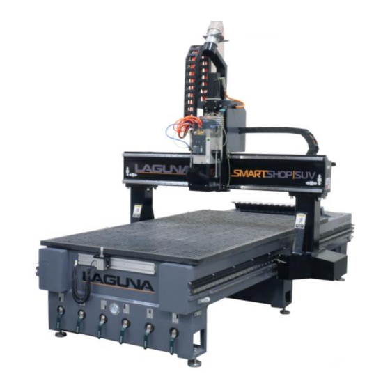
Smartshop SUV Manual 2021
Basic Operations-Main Screen Set-up, Set-up Menus, Machine Settings,
CNC Tool Data, Delivery Protocols, Warranties, Packaging/RMA
Procedures.
Laguna Tools
744 Refuge Way
Grand Prairie, TX. 75050
Direct Phone #: (800) 234-1976
1
Warranty Repair Information: (800) 332-4094
Advertisement

Related Manuals for Laguna Tools Smartshop SUV


Summary of Contents for Laguna Tools Smartshop SUV
- Page 1 Smartshop SUV Manual 2021 Basic Operations-Main Screen Set-up, Set-up Menus, Machine Settings, CNC Tool Data, Delivery Protocols, Warranties, Packaging/RMA Procedures. Laguna Tools 744 Refuge Way Grand Prairie, TX. 75050 Direct Phone #: (800) 234-1976 Warranty Repair Information: (800) 332-4094...
- Page 2 Table of Contents- • Main Screen Buttons & Flow. • CNC Positions. • Machine Settings. • Edit/Check “G” Code. • CNC Tools Data. • Axis Calibration. • Program Manager. • CNC Settings. • Axis Settings. • “Jog” Positions. • “Settings” from Main Screen. •...
-
Page 3: Main Screen
Main Screen Button(s) & Flow- “Main” Screen... - Page 4 Main / Home Screen Defined- Above is the Start-Up Home Screen- Park Tool = Pressing this button will put the active tool in spindle into its tool holder and leave the spindle empty. Preventive Maintenance Note- *****One should never leave a tool in spindle when machine is Idle. Leaving a tool in spindle will cause rust and damage to tool holder and or spindle.
- Page 5 Main / Home Screen Defined- Hold Settings Preview Program Hold = The Hold button is used to Pause a program run. Press the Run button to continue. NOTE: The spindle stays running during hold. Press stop button to stop the spindle and program. Run = The Run button is used to start a CNC Program.
- Page 6 Main / Home Screen Defined (Cont’d.)- Right Side Fields defined: Select Program drop down window = This field allows you to quickly select a program from the files copied to the controller’s memory. Active Tool = This references the current tool in spindle.
- Page 7 Main / Home Screen Defined (Cont’d.)- CNC Monitor = These 5 lines are displaying the CNC “G”-Code as it is running Coord’s Selector/Lower Right Drop Down = This is the selector for the X,Y, and Z coordinates displayed at the bottom of the Main Page.
- Page 8 Main Screen Buttons & Flow to proceed to CNC Positions- 1. Make sure one is in “Machine Coordinates”. “Set-Up” Screen Appears- 2. From the “Main Screen” select the “SET UP” Button, then it will proceed to “Set-Up” Screen.
- Page 9 CNC Positions- 2a. Select “CNC Positions” Button. 4a.Press “Main” Button to return to amin/Home Screen.
- Page 10 CNC Positions (Cont’d.)- 6. Then press the “Settings” Button...
- Page 11 CNC Positions (Cont’d.)-...
- Page 12 CNC Positions (Cont’d.)- 10. Press “Jog” Button to return to manual page to allow for manual jogging of the machine.
- Page 13 CNC Positions (Cont’d.)-...
- Page 14 CNC Positions (Cont’d.)-...
- Page 15 CNC Positions (Cont’d.)-...
- Page 16 CNC Positions (Cont’d.)- 20. Press “CNC Positions”.
- Page 17 CNC Positions (Cont’d.)-...
- Page 18 Machine Settings- This screen is to manage the machine settings. These settings consist of the Calibration, Tool Changer Locations, and Machines Limits. Pressing the “Save to CF Button” will write a copy of the machine settings to the controller’s memory. Pressing “Save Settings to USB”...
- Page 19 Machine Settings (Cont’d.)- “Import Settings from USB” = This is used for recovery purposes if the controller was to be replaced. “Units Field” = This is used to toggle the machine between Standard and Metric Units of Measure “Password Field” = This is used to access the much deeper settings that only a Laguna technician would need to access.
- Page 20 Machine Settings (Cont’d.)- Pressing “Save Settings to USB” is recommended so a hard copy of machine settings is available if service requires them to reinitialize the system. This is also very handy for or service people so your machine can be exactly replicated in our shop for troubleshooting.
- Page 21 “G-Code” Edit & Check- “Check Code” = This button will a program test by pre-running the code. This will check that the code can be run within the machine limits and “ZPO”= “Zero Point Origin”. “Code Editing” = Use the arrow keys and associated buttons to perform quick code edits on the machine.
- Page 22 From “Set-Up” Screen to CNC Tool Data- “Tools Screen”: This page is used for all data regarding Tooling Dimensions and Offsets “Tool Selection Drop Down Field” = Use this to select the tool in which you wish to manipulate. The tool number displayed propagates the fields below with its current data and allows for full manual adjustments if needed.
- Page 23 CNC Tool Data (Cont’d.)- “Tools Screen”: This page is used for all data regarding Tooling Dimensions and Offsets “Tool Selection Drop Down Field” = Use this to select the tool in which you wish to manipulate. The tool number displayed propagates the fields below with its current data and allows for full manual adjustments if needed.
- Page 24 From “Set-Up” Screen to CNC Tool Data (Cont’d.)- “Tools Screen”: This page is used for all data regarding Tooling Dimensions and Offsets “Manual Setting of Tool length” = “Execute Automatic Touch Off (TTO)” = Use the Jog function to move the Select the tool in which needs to be cutter to the table or work surface.
- Page 25 “Axis Calibration” Procedure-...
- Page 26 “Axis Calibration” Procedure-...
- Page 27 “Axis Calibration” Settings-...
- Page 28 “Axis Calibration” Settings-...
- Page 29 “Axis Calibration” Settings- 4.) Cont’d.
- Page 30 “Axis Calibration” Settings-...
- Page 31 From “Set-Up” Screen to Program Manager- “USER TAB” – TO THE CUSTOMER: DO NOT UTILIZE OR USE IN ANY WAY. “Programs Tab” – This displays the programs within a specified folder. “USB Tab” – This displays the programs from a USB stick when inserted into the control cabinet.
- Page 32 “Program Manager”- “Refresh Button” = This buttons polls the program storage area and brings the list up to a real time reference. “Multiselect Button” = This button allows the selection of multiple programs for pasting into another location or deleting. d.) Press the “Paste Button”...
- Page 33 From “Set-Up” Screen to Program Manager- “Refresh Button” = This buttons polls the program storage area and brings the list up to a real time reference. “Multiselect Button” = This button allows the selection of multiple programs for pasting into another location or deleting.
- Page 34 “CNC Settings”/Override Screen Defined- Enter the “CNC Settings” page from the Settings button in the lower left of the Main Screen or from the “CNC Set Up Button” on the Set-Up Menu Screen. “Overrides” = This screen allows for the adjustment of the “Rapid Feed Rate”, “Cutting Feed Rate”...
- Page 35 “CNC Settings” (Cont’d.)- CNC Settings- “MDI Field” = Manual Data Input is “Load Speed Settings” = ? for executing a single line of code “Load Speed Precision Settings”=? at a time or a “M Code”. Simply “Load Precision Settings”=? input the desired function and press “Execute Command”...
- Page 36 “CNC Settings (Cont’d.)- “Enable Control Blocks” = This is function for higher end users “Enable Optional Stop” = This that want to use “Control Blocks” such as shown below: Button enables a M0 to cause a program pause for additional operations or jigging during a program run.
- Page 37 “Axis Settings” Position-Setting “Absolute Zero”- “Home Zero Button” 1. Bring all Axis as close to the “Zero” position as possible. 2. Press “Re-Home Button” on Screen when homing in to “Absolute Zero (0) on the X, Y, & Z Axis of the Machine.
- Page 38 “Axis Settings” Positions-Setting “Absolute Zero” in case no “ReHome Button” available. 1. Bring all Axis as close to the “Zero” position as possible 2. Turn off machine and manually move the machine so that the end of the linear rails are 3”...
- Page 39 “Axis Settings” Positions-Setting “Absolute Zero” (Cont’d.) 4. “X” Axis ABS (ABS=Absolute).
- Page 40 “Axis Settings” Positions-Setting “Absolute Zero ” (Cont’d.) 5. “Z” axis ABS (ABS=Absolute).
- Page 41 “Axis Settings” Positions-Setting “Absolute Zero ” (Cont’d.) 6. Navigate to the Axis Settings page (Setup → Axis Settings). 7. Verify that the “X”, “Y”, and “Z” axis are all 3” from end of the rail to the bearing card and the Press “Re-Home”.
- Page 42 Alarm Screens- This screen will display the “3 Types of Alarms” that can be generated in the controller. The “Check Marks” is used to acknowledge and clear a single alarm at a time to see all that occurred. The “Next Button” will open the Axis Specific Alarms page.
- Page 43 Main Screen Buttons & Flow- Main Screen to “Jog” Screen “Main” Screen “Jog” Screen...
- Page 44 Jog Screen Defined- 1. Jog Past “Y” Safe = This button is used for maintenance and repair issues only. There is no operator function for this. 2. Dust Hood Up/Down = This button is used to manually retract or extend the dust hood. 3.
- Page 45 Jog Screen Defined (Cont’d.)- “Jogging Functions” = There are 3 settings for Jogging. ipm=Inches Per Minute DROP DOWN MENU for the X Axis, Y Axis, & Z Axis- 1st – Select the Jog type, Either Continuous Jog or a Step jog at a specified increment. 2nd –...
- Page 46 Main Screen Buttons & Flow- “Main” Screen “Program Preview Screen”...
- Page 47 “Settings” Button from Main Menu/ Override Screen Defined-...
- Page 48 “Settings” from Main Menu / Override Screen Defined (Cont’d.)- “MDI Field” = Manual Data Input is for executing a single line of code at a time or a “M Code”. Simply input the desired function and press “Execute Command” to activate. “Feed Rate Field”...
- Page 49 Main Menu “Settings” / Override Screen Defined (Cont’d.)- “Enable Control Blocks” = This is function for higher end “DRO Display” (Digital users that want to use “Control Blocks” such as shown Readout Display) = The below: Digital Read Out’s at the bottom of this screen reference the current machine...
- Page 50 Program Manager- “Program Preview Screen”: This screen will pre-run the selected “G-Code” and give a X and Y Graphical Representation of the Program as shown below.
- Page 51 Program Manager- “USER TAB” – TO THE CUSTOMER DO NOT UTLIZE OR USE IN ANY WAY. “Programs Tab” – This displays the programs within a specified folder. “USB Tab” – This displays the programs from a USB stick when inserted into the control cabinet.
- Page 52 Program Manager- “Refresh Button” = This buttons polls the program storage area and brings the list up to a real time reference. “Multiselect Button” = This button allows the selection of multiple programs for pasting into another location or deleting. d.) Press the “Paste Button”...
- Page 53 Set-Up / Networking Screen- The information contained in this screen is used for networking directly to the controller. This is needed for file transfers and remote diagnostic functions Via a P.C. Network. See Chapter on making a “Network Connection”.
- Page 54 Alarm Screens- The “Alarms” displayed on this screen are Axis Specific.
- Page 55 Schematics-...
- Page 56 Schematics-...
- Page 57 Schematics-...
- Page 58 Schematics-...
- Page 59 Schematics-...
- Page 60 Schematics-...
- Page 61 Schematics-...
- Page 62 Schematics-...
- Page 63 Schematics-...
- Page 64 Schematics-...
- Page 65 Schematics-...
- Page 66 Schematics-...
- Page 67 Schematics-...
- Page 68 Schematics-...
- Page 69 Delivery Protocol- • Most large machinery will be delivering on a tractor trailer 48'-53' long. Please notify Sales Representative with any Delivery Restrictions. • Customer is required to have a forklift (6000lb. or larger is recommended) with 72" forks or fork extensions and operator. •...
- Page 70 Parts & Service...
- Page 71 Machines sold through dealers must be registered with Laguna Tools within 30 days of purchase to be covered by this warranty. Laguna Tools guarantees all new machine sold to be free of manufacturers’ defective workmanship, parts and materials. We will repair or replace, without charge, any parts determined by Laguna Tools, Inc.
- Page 72 Technical support to install replacement parts is primarily provided by phone, fax, e-mail or Laguna Tools Customer Support Website. The labor required to install replacement parts is the responsibility of the user. Laguna Tools is not responsible for damage or loss caused by a freight company or other circumstances not in our control.
- Page 73 Laguna Tools Warranty-...
- Page 74 Support Website. The labor required to install replacement parts is the responsibility of the user. Laguna Tools is not responsible for damage or loss caused by a freight company or other circumstances not in our control. All claims for loss or damaged goods must be notified to Laguna Tools within twenty-four hours of delivery.
- Page 75 Laguna Tools Packaging/RMA Procedures- Dealer Machinery Warranty **Any machines returned to Laguna Tools must be returned with packaging in the same manner in which it was received. If a part or blade is being returned it must have adequate packaging to ensure no damage is received during shipping. In the...
- Page 76 Laguna Tools Packaging/Laguna Tools RMA Example- RMA #...
- Page 77 Laguna Tools Packaging/Laguna Tools BILL of LADING Example-...
Need help?
Do you have a question about the Smartshop SUV and is the answer not in the manual?
Questions and answers