Adaptec 2025ZCR Installation And User Manual
Sata and scsi raid controller
Hide thumbs
Also See for 2025ZCR:
- Installation manual (106 pages) ,
- Installation and user manual (169 pages) ,
- Datasheet (2 pages)
Table of Contents
Advertisement
Quick Links
Advertisement
Table of Contents

Related Manuals for Adaptec 2025ZCR


Summary of Contents for Adaptec 2025ZCR
- Page 1 ’ NSTALLATION AND UIDE SATA SCSI DAPTEC RAID C ONTROLLERS...
- Page 2 Copyright ©2004 Adaptec, Inc. All rights reserved. No part of this publication may be reproduced, stored in a retrieval system, or transmitted in any form or by any means, electronic, mechanical, photocopying, recording or otherwise, without the prior written consent of Adaptec, Inc., 691 South Milpitas Blvd., Milpitas, CA 95035.
- Page 3 Adaptec Customer Support If you have questions about installing or using your Adaptec product, check this — document first you will find answers to most of your questions here. If you need further assistance, use the support options listed below.
- Page 4 German: To speak with a Technical Support Specialist, call +49 89 43 66 55 22, Monday to Friday, 9:00 to 17:00, CET. For support via e-mail, submit your question to Adaptec’s Technical Support Specialists at French: To speak with a Technical Support Specialist, call +49 89 43 66 55 33, Monday to Friday, 9:00 to 17:00, CET.
- Page 5 Limited 3-Year Hardware Warranty 1. Adaptec, Inc. (“Adaptec”) warrants to the purchaser of this product that it will be free from defects in material and workmanship for a period of three (3) years from the date of purchase. If the product should become defective within the warranty period, Adaptec, at its option, will repair or replace the product, or refund the purchaser’s purchase price for the...
- Page 6 This device complies with part 15 of the FCC rules. Operation is subject to the following two conditions: (1) this device may not cause harmful interference and (2) this device must accept any interference received, including interference that may cause undesired operation. Adaptec, Inc. FOR HOME OR OFFICE USE European Union Compliance Statement...
- Page 7 Canadian Compliance Statement This Class B digital apparatus meets all requirements of the Canadian Interference- Causing Equipment Regulations. Cet appareil numérique de la classe B respecte toutes les exigences du Règlement sur le matériel brouilleur du Canada. Japanese Compliance (Voluntary Control Council Initiative) This equipment complies to class B Information Technology equipment based on VCCI (Voluntary Control Council for Interface).
-
Page 8: Table Of Contents
SATA Drives and Cables 2-2 SCSI Drives and Cables 2-2 Installing the Controller and Drives 2-3 Determining the Boot Controller 2-4 Creating a Bootable RAID 5 Array 2-5 Using the Adaptec RAID Configuration (ARC) Utility 2-6 Using the Adaptec Installation CD 2-7 Contents viii... - Page 9 Installing the Driver in an Existing NetWare System 3-10 Loading NetWare Drivers During Server Restart 3-11 Installing and Starting Adaptec Storage Manager Installing Adaptec Storage Manager on Windows 4-2 Installing Adaptec Storage Manager on Linux 4-3 Installing Adaptec Storage Manager on OpenServer 4-4...
- Page 10 Physical Devices View 5-3 Logical Devices View 5-3 Changing How Drives are Displayed 5-4 Collapsed and Expanded Views 5-4 Component Views 5-5 Adaptec RAID Configuration Utility (ARC) Overview A-1 Using the ACU A-2 Creating Arrays A-2 Managing Arrays A-4 Initializing Drives A-7...
- Page 11 Command Summary C-5 AFU Command Line – Step-by-Step C-9 Command Line Interface Introduction D-2 Terminology D-2 Adaptec 2410SA/2810SA Controllers Only D-2 Adaptec 21610SA Controllers Only D-2 All Controllers D-3 Accessing the CLI D-4 Accessing the CLI in MS-DOS D-4 Accessing the CLI in Windows D-4...
- Page 12 About RAID Simple Volume E-1 Spanned Volume E-2 RAID 0 E-2 RAID 1 E-2 RAID 5 E-3 RAID 10 E-4 RAID 50 E-5 About SCSI SCSI Device Support F-1 Setting SCSI IDs F-2 Changing SCSI Termination on the Controller F-2 Enabling CD Drive Support F-2 Mixing SE Devices with LVD Devices F-3 Controller Illustrations...
-
Page 13: Introduction
Introduction In this Chapter... Kit Contents Overview of the Installation Process System Requirements and Compatibility Controller Features About the Documentation Using the Adaptec Installation CD Installing the Adobe Acrobat Reader Software Tools Overview Safety Information 1-11 1-12 1-14 1-15 1-15... -
Page 14: Kit Contents
Kit Contents Your controller kit includes: Adaptec RAID controller. For controller illustrations, see Appendix Installation CD The cables supplied depend on the controller model: Adaptec Model 2020ZCR/2020SA 2025ZCR/2025SA 2120S/2200S/2130SLP/ 2230SLP 2410SA 2810SA 21610SA 1. Features a multimode terminator. All these SCSI RAID controllers support multimode termination. -
Page 15: Overview Of The Installation Process
Install Adaptec Storage Manager as described in d View, manage, and build additional arrays, as needed, using Adaptec Storage Manager. For an overview, see For details, refer to the Adaptec Storage Manager online Help. In an existing system that already has an operating system... -
Page 16: Drive Requirements
At least 128 MB of RAM An available 32- or 64-bit PCI slot An available 32- or 64-bit PCI or PCI-X slot (For Adaptec 2020ZCR, 2130SLP, and 2230SLP controllers only) 20 MB of free drive space... -
Page 17: Controller Features
SuSE Linux—Personal, Professional, and Enterprise Note: For the latest on Adaptec’s support of Linux, or to download driver sources, visit SCO— – UnixWare 7.1.x/OpenUNIX 8 (Base and Business Editions) – OpenServer 5.06 and 5.07 Novell—NetWare 6.x Controller Features This section contains the following subsections:... -
Page 18: Simple Volume
Event logging and broadcasting, including messaging for alphanumeric pagers. All except Adaptec 2020SA/2020ZCR—Optional battery backup module available. For details, see SATA RAID Controller Features Summary The following tables summarizes the features of the Adaptec SATA RAID controllers Form factor PCI compatibility PCI bus width (max) -
Page 19: Spanned Volume
SCSI RAID Controller Features Summary The following tables summarizes the features of the Adaptec SCSI RAID controllers. For more on SCSI, see Adaptec 2020ZCR Form factor Low- profile PCI/ compatibility PCI-X PCI bus width 64-bit (max) PCI bus speed 133 MHz... -
Page 20: Advanced Raid Features
Expansion (OCE) of existing arrays for all operating systems. With OCE, you can add new members to increase the capacity of an array without losing any data. For details, refer to the Adaptec Storage Manager online Help. Windows OCE allows you to use the additional capacity without restarting the system. - Page 21 Array Level Migration Adaptec RAID controllers support migration from one array type to another (provided your controller supports the new array type). The migration possibilities are; Current Array Type New Array Type RAID 0 RAID 5 or 10 RAID 1...
- Page 22 Audible Alarm Adaptec RAID controllers are equipped with an audible alarm that alerts you to situations that affect safety of your data. This section discusses the following topics: Sounding the Alarm Silencing the Alarm For additional details on how to control the alarm, see and the Adaptec Storage Manager online Help.
-
Page 23: About The Documentation
Adaptec Battery Backup Module Some Adaptec RAID controllers accept an optional Adaptec battery backup module. Notes: To see if the controller is available with battery modules, Controller Features on page To see the battery module connector location for your controller, see... -
Page 24: Using The Adaptec Installation Cd
Browsing the CD Booting from the CD with No Operating System The Adaptec installation CD is bootable. You can use it to start a computer that has no operating system and configure an array (provided your computer is set up to recognize bootable CDs). -
Page 25: Using The Cd Autorun In Windows
Install Adaptec Storage Manager—Installs the management software. For details, see Install Adobe Acrobat Reader—Installs Adobe Acrobat Reader for Windows to let you view the Adaptec documentation in PDF format. Versions of Acrobat Reader for other platforms are also included, see Installing the Adobe Acrobat Reader on page View Release Notes—Displays the... -
Page 26: Installing The Adobe Acrobat Reader
Public License (GPL) agreement. Installing the Adobe Acrobat Reader Both Adobe Acrobat Reader and Viewer are provided on the Adaptec installation CD. These applications allow you to view the PDF files on the Adaptec installation CD. Acrobat Reader is also available from Adobe as a free download. -
Page 27: Software Tools Overview
Software Tools Overview The Adaptec RAID controller includes the following tools to configure and manage your storage devices: Adaptec Storage Manager—Storage management application with a graphical user interface. Used to create, configure, and manage arrays. For details, see Chapters Adaptec RAID Configuration (ARC) Utility—BIOS-based utility that contains the following components: –... -
Page 28: Electrostatic Discharge
When you need to put your controller down, use an antistatic surface such as the bag supplied in your kit. If you plan to return the controller to Adaptec, put it back in its antistatic bag immediately. Introduction... - Page 29 Installing the Controller and Drives In this Chapter... SATA Drives and Cables SCSI Drives and Cables Installing the Controller and Drives Determining the Boot Controller Creating a Bootable RAID 5 Array...
-
Page 30: Installing The Controller And Drives
SATA Drives and Cables To install an Adaptec SATA RAID controller and drives, you need equal numbers of each of the following: Serial ATA hard drives Serial ATA cables (supplied in this kit) Configuration of Serial ATA drives is simple for the following reasons: There are no jumpers or switches to set on SATA controllers or hard drives. -
Page 31: Installing The Controller And Drives
If you have a low-profile controller and a low-profile computer cabinet, replace the original full-height bracket with the low- profile bracket supplied in Adaptec RAID controller kit. To verify the form factor of your controller model, see Features on page 1-5. -
Page 32: Determining The Boot Controller
Note: If your system will contain two or more bootable controllers, read this section. Otherwise, skip this section. The Adaptec RAID controller supports bootable drives and arrays. The default setting of the controller and system Setup usually allows you to install and boot from either a hard drive connected to the motherboard, or from a drive or array connected to the controller. -
Page 33: Creating A Bootable Raid 5 Array
Creating a Bootable RAID 5 Array Note: If you want to install an operating system on a drive or array connected to your Adaptec RAID controller, read this section. Otherwise, skip to installing the driver in your existing operating system, as described in This section describes how to create a bootable RAID 5 array with at least three drives. -
Page 34: Using The Adaptec Raid Configuration (Arc) Utility
Turn on the computer, then press Ctrl-A to enter the ARC utility. The first screen shows all installed Adaptec RAID controllers. If more than one Adaptec RAID controller is installed, highlight the boot controller, then press Enter. To select the ACU utility, press Enter. -
Page 35: Using The Adaptec Installation Cd
Note: SCSI only—You cannot create the RAID using a CD drive connected to the RAID controller. To build a bootable RAID 5 array using the Adaptec installation CD: Install the controller and drives, as described in Controller and Drives on page Start or restart the computer. - Page 36 Select the appropriate language on the Language screen, then press Enter. Read the information on the Licenses screen, then press Enter again. The Adaptec installation CD main menu is displayed. Select Launch Configuration Utility. The system launches Adaptec Storage Manager. The Adaptec Storage Manager screen appears.
- Page 37 12 When you are ready to continue, close all windows. The Main Menu is active. 13 Click Reboot to restart your system. 14 Remove the Adaptec installation CD. 15 If you want to make the array bootable, do so now. For details, page A-5.
-
Page 38: Installing The Driver
Installing the Driver In this Chapter... Overview of the Driver Installation Process Creating the Driver Disk Installing the Windows Driver Installing the Linux Module Installing the Unix Driver Installing the NetWare Driver... -
Page 39: Overview Of The Driver Installation Process
1 Set your system BIOS so that your computer boots from the CD-ROM drive. 2 Insert the Adaptec installation CD and turn on the computer. 3 Respond to the on-screen instructions as necessary to get to the Adaptec Start Menu. -
Page 40: Installing The Windows Driver
4 Click Create Driver Disk, then select the appropriate operating system. 5 If you selected Linux, you must also select the architecture: – i386—For Intel 386 or 486 computers – i586—For Pentium I or II computers – i686—For Pentium III, IV, or AMD K-6 computers –... -
Page 41: Installing The Driver In An Existing Windows System
Press S to specify that the driver is on the floppy disk, then press Enter. The computer reads the disk. 7 When the Adaptec driver is found, press Enter. Respond to the on-screen instructions to complete the installation. -
Page 42: Installing The Linux Module
SuSE Linux only—The controller is not supported as a bootable controller. In other words, you can only use Installing the Module in an Existing Linux System on page For the most up-to-date information on Adaptec’s support of Linux, visit Installing the Module When You Install Red Hat... -
Page 43: Installing The Module In An Existing Linux System
6 Follow the OpenServer instructions to complete the installation. 7 When the installation is complete, remove the driver disk and restart the computer. 8 Insert and mount the Adaptec installation CD. 2-3. page prompt, insert the driver disk and type... - Page 44 755 /usr/sbin/aacaifd /etc/rc.d/S98aacaifd Installing the Driver in an Existing OpenServer System To install the driver in an existing operating system: 1 Install and configure your Adaptec RAID controller and hard drives, as described in 2 Create the driver disk, as described on remove the driver disk.
-
Page 45: Unixware And Openunix
UnixWare and OpenUNIX This section contains the following procedures: Installing the Driver When You Install UnixWare or OpenUNIX Installing the Driver in an Existing UnixWare or OpenUNIX System Note: Although the driver disk you create for UnixWare and OpenUNIX differ, the installation procedures for these operating systems are the same. -
Page 46: Installing The Netware Driver
4 Restart the computer, then press Ctrl+A when prompted to access the ARC utility. Use ARC to create the RAID. For details, see Using the Adaptec RAID Configuration (ARC) Utility on page Install and configure a secondary controller, if any. -
Page 47: Installing The Driver In An Existing Netware System
Make a backup copy of the driver. 3 Create the driver disk, as described on remove the driver disk. Shutdown the server. Install and configure the Adaptec RAID controller as a secondary controller, as described in Start the server. Installing the Driver... -
Page 48: Loading Netware Drivers During Server Restart
A-2) or remotely using Adaptec Storage Manager (refer the online Help). Alternatively, you can create arrays using the Command Line Interface (CLI). Refer to the Adaptec Command Line Interface Reference Guide. Now that you have installed the drivers, refer to your NetWare documentation to modify disk partitions, apply hot fixes, or perform volume maintenance. - Page 49 The syntax to load the driver is: load [pathname]aacraid.ham slot=number [options] For example, the command to load the driver from the c:\nwserver directory, with the verbose= option load c:\nwserver\aacraid.ham slot=2 verbose=y Notes: Command line options are not case sensitive. Placing commas between command line options is optional.
-
Page 50: Installing And Starting Adaptec Storage Manager
Logging into Remote Systems After you have installed your Adaptec RAID controller and driver, you are ready to install and use Adaptec Storage Manager—a user- friendly graphical user interface that makes it easy for you to create and manage arrays without having to restart the computer and use the BIOS utility. -
Page 51: Installing Adaptec Storage Manager On Windows
Note: On Windows, Adaptec Storage Manager supports up to 16 Adaptec RAID controllers. To install Adaptec Storage Manager: 1 Insert the Adaptec installation CD and wait for the executable to start the installation. If this does not occur, browse the CD and click Autorun. -
Page 52: Installing Adaptec Storage Manager On Linux
Installing Adaptec Storage Manager on Linux Notes: With Linux, Adaptec Storage Manager supports up to 12 Adaptec RAID controllers. Adaptec Storage Manager includes the Java Runtime Environment (JRE). If a previous version of Adaptec Storage Manager is installed, you must remove it before upgrading. Any customization files you created when you used the previous version are saved and used in the upgrade. -
Page 53: Installing Adaptec Storage Manager On Openserver
CD; OSS643A for socket driver supplement from the Release Supplement 5.06a is helpful but not required. If a previous version of Adaptec Storage Manager is installed, you must remove it before upgrading. Any customization files you created when you used the previous version are saved and used in the upgrade. -
Page 54: Installing Adaptec Storage Manager On Unixware/Openunix
You need either the Java Development Kit (JDK) for SCO or the Java Runtime Environment (JRE) for SCO, version 1.3.1. To download these, visit If a previous version of Adaptec Storage Manager is installed, you must remove it before upgrading. Any customization files you may have created when you used the previous version are saved and used in the upgrade. -
Page 55: Installing Adaptec Storage Manager On Netware
/opt/RaidMan/RaidAgnt.sh Installing Adaptec Storage Manager on NetWare Notes: With NetWare, Adaptec Storage Manager supports up to 16 Adaptec RAID controllers. You need the latest Support Pack for your operating system so you can run the supported Java Virtual Machine (JVM). -
Page 56: Starting Adaptec Storage Manager
IP address, colon (:), and 34572 as the port number. 2 First the application flash screen will appear briefly , and then the Adaptec Storage Manager window will open with a log in dialog box superimposed. Enter a valid user name and password for a user on the system, and click Connect. - Page 57 Notes: Your Adaptec Storage Manager permissions will vary according to your OS permisssions: Administrator: The Administrator log in allows you to view and modify the RAID configuration. You can create and delete logical drives, verify logical drives, perform migrations, and add and remove hot-spare drives. To...
-
Page 58: Linux Operating Systems
StorMan.sh 3 First the application flash screen will appear briefly , and then the Adaptec Storage Manager window will open with a log in dialog box superimposed. Enter a valid user name and password for a user on the system, and click Connect. -
Page 59: Openserver Unixware And Openunix Operating Systems
OpenServer UnixWare and OpenUNIX Operating Systems 1 Change to the Adaptec Storage Manager installation directory by typing: cd /opt/RaidMan 2 Type the following command and press Enter: sh RaidMan.sh NetWare Operating System To start Adaptec Storage Manager on the NetWare operating... - Page 60 Note: The username and password are case sensitive. Once you are logged in for the first time, you can add new accounts and change account passwords. For details, refer to the online Help. Installing and Starting Adaptec Storage Manager admin adaptec 4-11...
-
Page 61: Understanding Adaptec Storage Manager
This chapter provides an overview of Adaptec Storage Manager, the user-friendly graphical user interface that you use to easily create and manage arrays. For more details on using Adaptec Storage Manager to set up and manage arrays, refer to the online Help. -
Page 62: Overview
Check with your vendor, product documentation, or online Help for supported features. Overview Adaptec Storage Manager provides an expandable tree view of the systems and controllers you are managing. You can perform most configuration and management tasks by selecting a controller from the tree and working with related objects. -
Page 63: Physical Devices View
RAID level of each device, and whether a logical device is protected by a hotspare. You can create and delete logical devices in the Logical devices view by selecting the Create option and using the Create wizard. Understanding Adaptec Storage Manager... -
Page 64: Changing How Drives Are Displayed
Collapsed and Expanded Views You can display a collapsed or expanded view of the system configuration. Initially, Adaptec Storage Manager displays a collapsed textual view of the configuration information in both the Logical devices and Physical devices views. -
Page 65: Component Views
When you click a hotspare, the logical devices protected by that spare are highlighted. In the graphical views, if the logical device uses only part of the available storage, only those segments are highlighted (in dark blue). Understanding Adaptec Storage Manager... -
Page 66: Adaptec Raid Configuration Utility (Arc)
Using the Disk Utilities Viewing the Event Log Overview The Adaptec RAID Configuration (ARC) utility is part of the controller BIOS. The utility includes: Array Configuration Utility (ACU)—Used to create, configure, and manage arrays, and make arrays bootable. Also used to initialize and rescan drives. -
Page 67: Using The Acu
The Adaptec RAID Controller menu presents the following options: Array Configuration Utility SATASelect and SCSISelect Utilities Disk Utilities To select a menu option in ARC, browse with the arrow keys, then press Enter. Sometimes, selecting an option displays another menu;... - Page 68 Note: The ACU can be used to assign array properties only prior to building the array. After the array is built, you need to use Adaptec Storage Manager to assign properties. To assign properties to the new array: 1 In the Array Properties menu, select an array type, then press Enter.
-
Page 69: Managing Arrays
6 When you are finished, select Done. The array build starts. Managing Arrays With the Manage Arrays option, you can perform the following tasks: Viewing Array Properties Making an Array Bootable Deleting Arrays Managing Failover Drive Assignments Adaptec RAID Configuration Utility (ARC) - Page 70 You cannot make a non-00 array bootable while the array is in a build/verify or rebuild process. You may need to change the system BIOS to modify the boot order. For more information, refer to the system documentation. Adaptec RAID Configuration Utility (ARC) page A-10.) When...
- Page 71 2 From the List of Arrays dialog box, select the array to which you want to assign a hotspare, then press Ctrl+S. The Hotspare Management for Array dialog box is displayed, which shows the drives that can be assigned as hotspares. Adaptec RAID Configuration Utility (ARC)
-
Page 72: Initializing Drives
Do not initialize a disk that is part of a boot array. The boot array is the lowest numbered array (normally 00) in the List of Arrays dialog box. For information on determining which disks are associated with a particular array, see Viewing Array Properties on page Adaptec RAID Configuration Utility (ARC) A-5. -
Page 73: Rescanning Drives
To rescan the drives connected to the controller: 1 Restart the computer, then press Ctrl+A when prompted to access the ARC utility. 2 From the ARC menu, select Array Configuration Utility. 3 Select Rescan Drives. Adaptec RAID Configuration Utility (ARC) -
Page 74: Using Sataselect And Scsiselect
(If you changed any host adapter settings, you are prompted to save the changes before you exit.) Choose Yes to exit and restart the computer. Any changes you made take effect after restart. Adaptec RAID Configuration Utility (ARC) Applies to... All controllers... -
Page 75: Controller Configuration Options
Failover Array Disabled Background Consistency Check BBS Support Enabled Adaptec RAID Configuration Utility (ARC) Models Affected Description When Enabled, write cache is enabled, providing maximum drive performance. When Disabled, no write cache is used on the drive. By default, the drive’s setting is used. - Page 76 Media Devices Support Alarm Control Enabled 1. BBS systems containing SCSI controllers only. 2. Adaptec 2120S/2130SLP/2200S/2230SLP Adaptec RAID Configuration Utility (ARC) Models Affected Description When Enabled in systems that support BBS, the controller presents attached bootable devices up to the host system's BIOS for boot device selection.
-
Page 77: Sata Configuration Options
Caution—When Enabled, there is a potential for data loss or corruption during a power failure. Description Sets the controller’s SCSI ID. Adaptec recommends that you leave the controller set to the default, which gives it the highest priority on the SCSI channel. - Page 78 Enable Disconnection Initiate Wide Negotiation Packetized 1. Adaptec recommends that you not enable QAS if you are using an enclosure that contains Ultra320 expander ICs. Adaptec RAID Configuration Utility (ARC) Using the Disk Utilities on Description Determines the maximum data transfer rate that the SCSI channel supports.
-
Page 79: Using The Disk Utilities
Most drives are formatted at the factory and do not need to be formatted again. Caution: During formatting, all data is destroyed. Before proceeding, back up any data. – Verify Disk Media—Scans the media of a drive for defects. Any errors found are corrected. Adaptec RAID Configuration Utility (ARC) A-14... -
Page 80: Viewing The Event Log
2 If multiple controllers are installed, select the controller you want to configure, then press Enter. 3 From the ARC menu, press Ctrl+P. The Controller Service Menu appears. 4 Select Controller Log Information, then press Enter. The current log is displayed. Adaptec RAID Configuration Utility (ARC) A-15... -
Page 81: Acu For Dos
Creating the ACU Utility Disk The DOS version of this utility runs from a floppy disk that you need to create using the following procedure: 1 To find the ACU executable, Adaptec installation CD that relates to your controller model. Adaptec Model Path 2020ZCR... -
Page 82: Running The Acu Interactively
Adaptec Model Path 2200S packages/firmware/adp2200S 2230SLP packages/firmware/adp2230SLP 2410SA packages/firmware/adp2410SA 2810SA packages/firmware/adp2810SA 2 Insert a bootable floppy disk and copy Running the ACU Interactively To run the ACU interactively: 1 Insert the ACU utility disk you created in Utility Disk. 2 Start or restart your computer. -
Page 83: Running The Acu Using Scripts
Running the ACU Using Scripts To use the ACU scripting features, use the ACU command, specify a script file (see Creating the Script File Manually on page specify one (but not both) of the required switches listed in the table below. -
Page 84: Playback Mode
Playback Mode In this mode, the ACU reads the contents of the specified script file and creates arrays based on the keywords specified in the script. The syntax is ACU /P <file> where file is the parameter specifying name of the script file. The file parameter can include a drive, directory, filename, and extension. -
Page 85: Creating The Script File Manually
Notes: Record Mode can be used to record only one controller at a time. Therefore, if you want to record multiple controllers, record them separately using separate script files. Because the ACU supports only a subset of array types available, it cannot record all the possible array configurations. - Page 86 Array Definition Block Keywords The array definition block always begins with the keyword Array and ends with the keyword End. The other required array definition keywords are Drives and Type. The array definition keywords are listed in the table below alphabetically. Keyword Required? Array...
- Page 87 The keywords are described in detail in the sections that follow. Array Keyword Array is a required keyword, indicating the start of an array definition block. The syntax is Array=<label>, where label is an optional alphanumeric string. Examples Array Array=MyData Drives Keyword Drives is a required keyword, specifying the devices to use in creating the array.
- Page 88 HotspareDrives Keyword HotspareDrives is an optional keyword, specifying the hotspares to assign to the array. The syntax for listing hotspares is the same as Drives Keyword on page no hotspares are assigned to the array. Notes: HotspareDrives creates only dedicated hotspares. If the same drive is assigned to protect multiple arrays, only the last array that drive is assigned to is protected.
- Page 89 Notes: InitializeAll is a global keyword that you need to specify only once. InitializeAll is always performed prior to array creation regardless of its position in the script. If both InitializeAll=Yes and InitializeAll=No are specified in the same script file, InitializeAll=Yes is always the overriding value.
- Page 90 ReadCache Keyword ReadCache indicates whether the array uses read caching. Possible values are: Yes (the default)—Enable read caching. No—Disable read caching. Example ReadCache=Yes Size Keyword The Size keyword specifies the size of the array. Specify Maximum (the default) to create an array using the maximum available space, based on the array type and drives selected.
- Page 91 Type Keyword Type is a required keyword, indicating the array type. There is no default value. The Type keyword values are: Volume RAID0 RAID1 Note: For information about which array types your controller supports, see Controller Features on page Wait Keyword Wait is an optional keyword that you can use to tell the ACU to allow the ACU to continue while the build/verify or clear completes in the background;...
-
Page 92: Channel Definition Block Keywords - Scsi Only
Normally, the SCSI controller is assigned SCSI ID 7 on each of its channels. You can specify any ID value between 0 and 7. Caution: Do not change the SCSI ID of the controller unless directed to do so by Adaptec Technical Support. Example ControllerID=7 End Keyword End is a required keyword, indicating the end of the block. -
Page 93: Acu Error Codes
ACU Error Codes When the ACU detects an error, it reports the error and exits immediately. If a log file is specified, the ACU writes the error code to the log file. Otherwise, it displays the error code on the screen. The possible error messages returned by the ACU are listed in the table below. -
Page 94: Example - Running The Acu With A Script
ACU Error Codes "Continued" Code Description Insufficient memory to run the application—There is not enough memory to run the ACU. Incorrect controller number—The controller number you specified is invalid or out-of-range. Controller not responding—The controller has stopped responding to the ACU. Build/Verify/Clear failed—The build/verify or clear operation for one or more arrays has failed. - Page 95 The following sample script file creates a maximum-size three- drive RAID 5. # Create a maximum size RAID 5 labeled ‘MyData’ Array=MyData Type=RAID5 Size=Maximum # Use the maximum stripe size StripeSize=64 # Clear the array (don’t build/verify it) Method=Clear # Don’t wait for clear to complete Wait=No # Use drives 0, 1, 2 Drives=0:0:0, 0:1:0, 0:2:0...
-
Page 96: Adaptec Flash Utility (Afu)
Running the AFU from the Command Line Introduction The Adaptec Flash Utility (AFU) is a DOS utility used to update, save, or verify the RAID controller’s firmware BIOS, and NVRAM. Caution: The AFU is easy to use and contains safeguards to prevent you from accidentally damaging the controller’s flash... -
Page 97: System Requirements
Compatibility The AFU has the following compatibility issues: Supports HIMEM.SYS; compatible with other DOS drivers running under HIMEM.SYS (for example, SMARTDRV.SYS and SETVER.SYS). Does not support DOS extenders installed in memory, such as EMM386.SYS and DOS4GW. Adaptec Flash Utility (AFU) -
Page 98: Creating The Firmware Floppy Disks
From the Adaptec installation CD—The CD includes the AFU executable, AFU.exe separate flash image. The flash image may be comprised of multiple UFI files. You can locate the necessary files on the Adaptec installation CD at the locations listed below. Adaptec Model Path 2020ZCR... -
Page 99: Running The Afu From The Gui
3 At the DOS command prompt (typically arguments. The AFU’s main menu is displayed. 4 Choose Select Controllers and select the Adaptec RAID controllers to be flashed. 5 Choose Select an Operation. 6 Choose any available AFU function and follow the on-screen instructions. -
Page 100: Running The Afu From The Command Line
The following example shows a typical system response to a LIST command. A:\> AFU LIST Adaptec Flash Utility V4.0-0 B5749 (c)Adaptec Inc. 1999–2002. All Rights Reserved. Controllers Detected and Recognized: Controller #0 (03:05:00) Adaptec 2410 Adaptec Flash Utility (AFU) ), type AFU followed... - Page 101 AFU looks for, or creates, its UFI files in the default location. Note: You cannot specify the name of a UFI file, only its path. UFI filenames are predefined, based on the controller type. Adaptec Flash Utility (AFU)
- Page 102 (c)Adaptec Inc. 1999–2002. All Rights Reserved. Updating Controller 0 (Adaptec 2410) Reading flash image file (Build 5749) AFU is about to update firmware on controllers Adaptec 2410 ***PLEASE DO NOT REBOOT THE SYSTEM DURING THE UPDATE*** This might take a few minutes.
- Page 103 The following example shows a typical system response after a verify command has been performed. A:\> AFU VERIFY /C 0 Adaptec Flash Utility V4.0-0 B5749 (c)Adaptec Inc. 1999–2002. All Rights Reserved. Reading flash image file (Build 5748) Controller #0: Adaptec 2410 ROM: Checksum: 797B [VALID] (Build 5748)
-
Page 104: Afu Command Line - Step-By-Step
6 If you have multiple controllers only—At the DOS prompt, type afu list and press Enter. This command displays the Adaptec RAID controllers in your system. Note the controller number for the controller you want to update; you may need it in... - Page 105 /C < Where <controller_number_a> and <controller_number_b> is the number of one of the Adaptec RAID controllers whose firmware you are updating. To upgrade controllers 0, 2, and 3 for example, type: afu update /C 0, 2, 3 c Updating the Flash on All Controllers Simultaneously—To...
-
Page 106: Command Line Interface
Command Line Interface In this Appendix... Introduction Terminology Accessing the CLI Using the CLI General Control Commands Container (Array) Commands Controller Commands Disk Commands Logfile Commands Task Commands Enclosure Commands Using Automated Command Scripts D-15 D-16 D-25 D-28 D-32 D-32 D-34 D-38... -
Page 107: Introduction
The Command Line Interface (CLI) allows you to configure and manage controller components. The CLI contains most of the functionality offered by Adaptec Storage Manager, plus some additional functionality not offered by Adaptec Storage Manager. CLI commands allow you to automate testing or array creation in a production environment using Windows command scripts and Linux and Unix shell scripts. -
Page 108: All Controllers
For example, port 5 is 0:5:0; port 12 is 1:4:0. All Controllers The following terms are used in discussing the CLI: Array, container—A logical disk created from available space and made up of one or more partitions on one or more physical disks. -
Page 109: Accessing The Cli
Note: The following procedure assumes that you accepted the default location for the software during installation. 1 Click the Start button. 2 Click Programs. 3 Browse to Adaptec Storage Manager. The Adaptec program group is displayed. 4 Click CLI. Note: In Windows, when the CLI executes a background command, it displays status information in the title bar of a DOS command prompt window. -
Page 110: Using The Cli
From the NetWare server console To access the CLI from the NetWare server console, type aaccli at the prompt. When the system displays the CLI> prompt, which indicates that you can now use CLI commands. Using the CLI This section contains some examples of using CLI commands to perform common tasks. - Page 111 Displaying Information about Your Array After creating an array, use the container list command to display information about the array. In the following example, the Num Label column indicates the array ID 0 and the array label Venus. The Type column indicates a volume set. The Total Size column indicates that the array is 100 MB.
- Page 112 Creating a RAID 1 To create a RAID 1, use the container create new_mirror command. In the following example, a RAID 1 is created on devices 0:02:0 and 0:03:0 using 100 MB of available space from each device. AAC0> container create new_mirror ((0,2,0), 100M) (0,3,0) Executing: container create new_mirror ((CHANNEL=0,ID=2,LUN=0),104,857,600 ) (CHANNEL=0,ID=3,LUN=0) Creating a RAID 5...
-
Page 113: Managing Failover Options And Hotspares
Managing Failover Options and Hotspares To assign one or more hotspares to a single array, use the container set failover command. To assign one or more spare disks for all arrays, use the container set global_failover command. These commands allow you to add hotspares to an array prior to a drive failure so that the array contains the resources it needs to survive a failure. -
Page 114: Displaying Controller Information
Adapter Name column indicates that AAC0 is the name of the controller installed on the computer. The example also indicates the controller’s path ( \\.\ CLI> controller list Executing: controller list Adapter Name Adapter Type ------------ ------------ \\.\AAC0 Adaptec xxxxx Command Line Interface Availability ------------ read/write... - Page 115 AAC0> controller details Executing: controller details Controller Information ---------------------- Remote Computer: . Device Name: AAC0 Controller Type: Adaptec xxxxxx Access Mode: READ-WRITE Controller Serial Number: Last Six Digits = 8A277A Number of Buses: 2 Devices per Bus: 15 Controller CPU: i960...
-
Page 116: Displaying Disk Information
Displaying Disk Information The CLI allows you to monitor or manage disk attributes, prepare a disk for use by a controller, and detect defects using the following commands: Disk List Disk Show Defects Disk Verify Disk List The disk list attributes are defined as follows: Device ID—An ID number assigned to each device attached to a channel Device Type—Reports whether the device is a disk, printer,... -
Page 117: Displaying Array Information
Disk Show Defects The disk show defects command shows the following types on information: Total number and location of primary defects (defects that originate during manufacturing) Total number and location of grown defects (defects that originate after manufacturing) Example In the example below, the drive contains five primary defects and no grown defects: AAC0>... - Page 118 Command Line Interface Root Special File (Unix/Linux only)—File associated with the array and created by the OS after array creation. Appears in the Num Label column. Array Number—ID of an array (0 to 63). Array Label—Name assigned to an array. Not automatically assigned.
- Page 119 Mirror Set Create—Creation of a RAID 1 (mirror). Mirror Set Normal—The RAID 1 is in the normal state. Reconfiguration Copy Container—An array is being used as a copy (hidden) array (Copy). Reconfiguration Destination Container—An array is being used as a destination (hidden) array (Dest). Reconfiguration RAID 5 Set—An array is being used as a RAID 5 (hidden array).
-
Page 120: Cli Command Dictionary
CLI Command Dictionary This section contains a command reference for the following command groupings: General Control Commands Container (Array) Commands Controller Commands Disk Commands Logfile Commands Task Commands Enclosure Commands General Control Commands close Closes the currently opened controller. exit Closes the opened controller and exits the CLI. -
Page 121: Container (Array) Commands
open [/readonly={boolean}] [/domain={string}] {name} Opens a controller, a prerequisite for any controller command to be used on that controller. Parameters {name}—Computer name and the controller to open. Switches /readonly—If TRUE, the controller is opened for read-only access. (The default is FALSE.) If you open a controller with read-only access, you can use only those commands that do not change the controller configuration. - Page 122 Switches /always—Specifies whether to clear the array even if it has data on it. The default is FALSE, meaning that the command clears the array only if it has no data on it. All user files must be closed; the /always switch cannot override this restriction. /wait—...
- Page 123 Switches /io_delay—Number of milliseconds between each I/O used for the RAID 1 create. /wait— If FALSE (the default), the operation is performed in the background and the command prompt is returned immediately. If TRUE, the operation is performed immediately and the command prompt is returned only when done.
- Page 124 container create raid5 [/cache={boolean}] [/stripe_size={integer}] [/clear={boolean}] [/label={string}] [</quick_init={boolean}>] [/scrub={boolean}] [/wait={boolean}] {free_space} [{device_ID}...] Creates a RAID 5. Parameters {free_space}—Drive and its associated available space used to create the array. {device_ID}—One or more devices whose available space to be used to create the array. Switches /cache—Specifies whether to enable the array’s cache.
- Page 125 Switches /cache—Specifies whether to enable caching on the array. /stripe_size—Stripe size for the RAID 0. The default is 64 KB. /label—Label to assign to the new RAID 0. container create volume [/cache={boolean}] [/label={string}] {device_ID}, {free_space}, {device_ID}, [{free_space}...] Creates a volume. Parameters {device_ID}—Drive and its associated available space to be used to create the volume.
- Page 126 container list [/all={boolean}] [/full={boolean}] [{container}] Lists information about the arrays on the controller. Parameters {container}—ID number of the array containing information to display. Switches /all—Specifies whether to list all containers on the system. /full—Specifies whether to display detailed information. container move {container1} {container2} Moves the first array number specified to the second array number specified;...
- Page 127 Parameters {container}—ID number of the array to set to read-write access. container reconfigure [/stripe_size={integer}] [/mirror={boolean}] [/partition_move={boolean}] [/partition_size={integer}] [/raid5={boolean}] [/raid10={boolean}] [/restart={boolean}] [/stripe={boolean}] [/volume={boolean}] [/wait={boolean}] {container} [{device_ID}...] Changes the configuration of an array. Parameters {container}—ID number of the array to reconfigure. {device_ID}—One or more devices. Switches /stripe_size—Stripe size of the array.
- Page 128 Parameters {container}—ID number of the array whose assigned failover disk is to be removed. {device_ID}—ID for the device to remove as a failover disks. container remove global_failover {device_ID} [{device_ID}...] Removes a global failover assignment. Parameters {device_ID}—ID for the device to remove as a failover disk. container restore RAID5 {container} Tries to restore a RAID 5 that has a number of dead partitions as members.
- Page 129 container set cache [/read_cache_enable={boolean}] [/unprotected={boolean}] [/write_cache_enable={boolean}] {container} Sets cache parameters for a specific array. Useful only if a native OS's file system resides on the array. Parameters {container}—ID number of the array on which to set cache parameters. Switches /read_cache_enable—Specifies whether to enable the read- ahead cache.
-
Page 130: Controller Commands
Parameters {container}—ID number of the array on which to set the I/O delay. {integer}—Number of milliseconds the controller waits between I/O operations. container set label {container} {label} Assigns a new label to the array. Parameters {container}—ID number of the array to which to assign a label. - Page 131 controller details Shows details about the open controller and software. controller firmware compare [/C{controller}] [{controller}...] [/D{UFI_file_path}] Compares the contents of each of the flash components on a controller to the corresponding image in User Flash Image (UFI) files and indicates whether they match. Switches /C{controller}—ID representing the set of controllers on which to perform the firmware comparison.
- Page 132 controller list [/domain={string}] [{string}] Lists all controllers or displays information about the currently opened controller. Parameters {name}—Computer name from which to display all controllers or specific information about the open controller. Switches /domain (Windows only)—Specifies the domain in which the host to be searched resides.
-
Page 133: Disk Commands
controller set container_verify [/verify_enabled={boolean}] Turns the container verify task on or off. Switches /verify_enabled—Specifies whether to turn on or off the container verify feature. The default is TRUE, which means the command turns on the container verify feature. controller show automatic_failover Displays the automatic failover status (enabled or disabled) for the controller. - Page 134 Switches /always—Specifies whether to initialize the disk even if the disk has existing data. (Cannot override open files.) The default is FALSE. /unconditional—Specifies whether to initialize the disk even if arrays on the disk have open files. The default is FALSE. disk list [/all={boolean}] [/full={boolean}] [{device_ID}] Lists the disks available on the controller.
- Page 135 Switches /all—Specifies whether to enable SMART configurations for all disks. /clear—Clears the SMART error counts for the disk. /enable_exceptions—Specifies whether to enable SMART exception reporting. /logerr—If FALSE (the default), logging of SMART exception reports is dissabled. If TRUE, logging of SMART exception reports is enabled.
- Page 136 Parameters {device_ID}—ID number of the device for which to display SMART information. Switches /all—Specifies whether to display SMART configurations for all disks. /full—Specifies whether to display detailed SMART configuration information for one or all disks. /view_changeable—Specifies whether to display the configuration information that can be set on a SMART disk.
-
Page 137: Logfile Commands
disk zero [/repair={boolean}] [/wait={boolean}] {device_ID} Clears an entire disk (by writing zeros). All data is erased and cannot be recovered. Parameters {device_ID}—ID number of the device to clear. Switches /repair—If FALSE (the default), the command only reports failures. If TRUE, bad blocks are automatically repaired, if possible. - Page 138 task list [/all={boolean}] [{integer}] Lists the tasks running on the controller. Parameters {integer}—Task ID. Switches /all—Specifies whether to list all currently running tasks. task resume [/all={boolean}] {integer} Resumes a task that was suspended or all of the tasks that were suspended.
-
Page 139: Enclosure Commands
Enclosure Commands Note: You can use the enclosure commands only with enclosures that support Version 1.0 of the SAF-TE specification. enclosure activate slot {enclosure} {slot} Activates a device in a slot in the SAF-TE enclosure. Parameters {enclosure}—ID number of the enclosure management device on which to activate a device. - Page 140 Parameters {enclosure}—ID number of the enclosure management device on which to prepare a slot. {slot}—Unit number of the slot. enclosure set alarm [/on={boolean}] {enclosure} Turns the audible alarm on or off. Parameters {enclosure}—ID number of the enclosure management device whose audible alarm to set. Switches /on—Specifies whether to turn the audible alarm on or off.
- Page 141 Parameters {enclosure}—ID number of the enclosure management device. {powersupply}—Unit number of the power supply. Switches /off—Specifies whether to turn on or off the power supply of the unit number. enclosure set scsiid {enclosure} {slot} {device_ID} Sets the ID number of the device slot. Parameters {enclosure}—ID number of the enclosure management device.
- Page 142 Parameters {enclosure}—ID number of the enclosure management device for which to display power supply status. {powersupply}—Unit number of the power supply. enclosure show slot [{enclosure}] [{slot}] Displays the status of a specific device slot on a specific enclosure. Parameters {enclosure}—ID number of the enclosure management device for which to display device slot status.
-
Page 143: Using Automated Command Scripts
Using Automated Command Scripts To execute a CLI command script, type the at sign (@), followed by the filename that contains the CLI commands, for example: AAC0>@commandscript.txt In a CLI command script text file, each line ends with a line feed inserted by pressing Enter. -
Page 144: About Raid
Note: Select RAID drives of equal capacity and performance. Otherwise, the RAID tends to be limited in capacity and performance to that of the smallest and slowest drive. Simple Volume A simple volume consists of a single drive. for Adaptec Controller Models 2120S/ 2130SLP 21610SA 8 / 2... -
Page 145: Spanned Volume
Spanned Volume A spanned volume is created by joining, or concatenating, two or more drives. The drives do not have to be of equal capacity and are connected end-to-end. A spanned volume offers no redundancy and no performance advantage over a single drive. RAID 0 A RAID 0 is created by striping data across two or more drives. -
Page 146: Raid 1
RAID 1 offers no write performance advantage over a simple volume configuration. However, because the drives share read load equally, RAID 1 provides improved read performance. An example of a RAID 1 array is shown below. RAID 1 Drive Drive Data 0 Data 0 Data 1... -
Page 147: Raid 5
Using parity minimizes the storage cost of redundancy. Because only one drive is used to store parity, a three-drive array, which is the worst case, uses only one-third of the total capacity for redundancy. In larger arrays, the storage cost of redundancy decreases proportionately RAID 5 write performance is limited by the need to generate parity data for every write. -
Page 148: Raid 50
Drive Data 0 Data 1 Parity A1 Data 4 Data 8 Parity A2 Data 12 Data 13 Note: Adaptec 2410SA does not support RAID 50. RAID 50 Top-Level Arrays Second-Level Arrays RAID 0 Drive Drive Parity A0 Data 2 Data 5... -
Page 149: About Scsi
The SCSI RAID controller is designed to work with Ultra320 SCSI hard drives. Although the controller also works with Ultra2 or higher SCSI drives and peripherals, performance is reduced. Adaptec does not recommend using SCSI devices older than Ultra2. Operating Systems All except Linux Caution: HVD devices are not supported and will damage your controller. -
Page 150: Setting Scsi Ids
Disabled. For details, see All these SCSI controllers support multimode SCSI termination. Enabling CD Drive Support Note: Adaptec SCSI RAID controllers do not support CD drives in Linux systems. If you attached a CD drive to the controller, you need to configure... -
Page 151: Mixing Se Devices With Lvd Devices
Select SCSISelect Utility, then select Controller Configuration. Using the arrow keys, enable CD-ROM Boot Support and Removable Media Devices Support. Press Esc until the Reboot window appears. Restart the computer. Mixing SE Devices with LVD Devices If you are mixing SE devices with LVD devices: Ensure proper termination by using a cable (like the one in the kit) with a built-in multimode terminator and appropriate device adapters. -
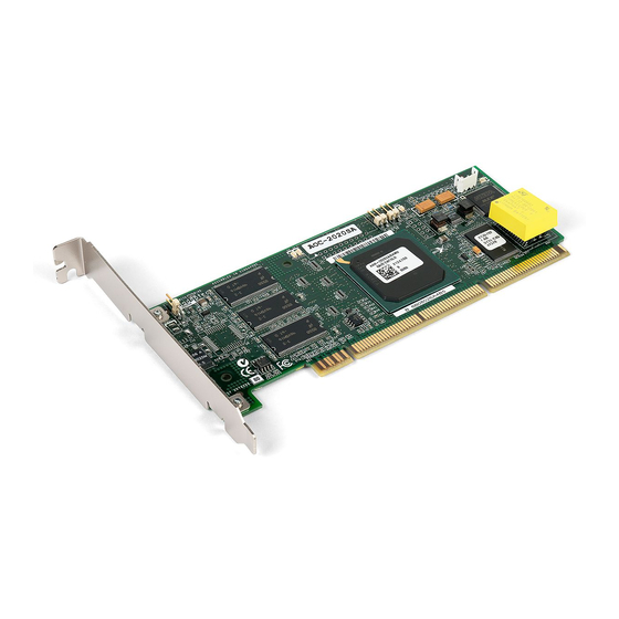
Page 152: Controller Illustrations
Controller Illustrations This Appendix shows the Adaptec RAID controllers. PCI/PCI-X connector Low-profile bracket Adaptec 2020SA/2020ZCR Component Layout... - Page 153 Controller Illustrations SO-DIMM Connector Adaptec 2025SA/2025ZCR Component Layout Battery connector Internal high-density SCSI connector Adaptec External VHDCI SCSI Connector PCI connector Low-profile bracket Adaptec SCSI RAID 2120S Component Layout...
- Page 154 External VHDCI SCSI connector Adaptec SCSI RAID 2130SLP Component Layout External VHDCI SCSI connectors Adaptec SCSI RAID 2200S Component Layout Internal high-density SCSI connector Adaptec PCI-X connector Low-profile bracket Internal high-density SCSI connectors Adaptec PCI connector Low-profile bracket Controller Illustrations...
- Page 155 Controller Illustrations Internal high-density Battery connector SCSI connectors Adaptec External VHDCI SCSI connectors PCI-X connector Low-profile bracket Adaptec SCSI RAID 2230SLP Component Layout...
- Page 156 Controller Illustrations SATA ports PCI connector Full-height bracket Adaptec SATA RAID 2410SA Component Layout Adaptec SATA RAID 2410SA Port Numbers...
- Page 157 Controller Illustrations Battery connector SATA ports PCI connector Full-height bracket Adaptec SATA RAID 2810SA Component Layout Adaptec SATA RAID 2810SA Port Numbers...
- Page 158 Controller Illustrations Battery connector SATA ports SATA ports PCI connector Full-height bracket Adaptec SATA RAID 21610SA Component Layout 9 11 12 14 8 10 13 15 Adaptec SATA RAID 21610SA Port Numbers...
-
Page 159: Specifications
Ambient temperature without battery backup module Relative humidity Altitude Note: Forced airflow is recommended, but not required. DC Power Requirements Ripple and noise DC Voltage Current Requirements Adaptec Model 2020SA/2020ZCR/2025SA/ 2025ZCR 2120S 2130SLP/2230SLP 2200S 2410SA 2810SA 21610SA 0 °C to 50 ° C... -
Page 160: Glossary
Glossary activity See task. Array Configuration Utility. Used to create, configure, and manage arrays from the controller’s BIOS or MS-DOS. array A logical disk created from available space and made up of one or more partitions on one or more physical disks. Arrays are typically used to provide data redundancy or enhanced I/O performance. - Page 161 Glossary bootable array Array configured as the boot device. build Background initialization of a redundant array. The array is accessible throughout. RAID 1 copies the contents of the primary drive to a secondary drive. See also clear. See channel. cache Fast-access memory on the controller that serves as intermediate storage for data that is read from, or written to, drives.
- Page 162 Glossary consistency check command The controller continuously performs a verification on a redundant array to data integrity. In the case of RAID 1 or 10, consistency checks assure that the data between like blocks match. In the case of a RAID 5, consistency checks assure that data in the stripe and the calculated parity for the stripe match.
- Page 163 See also redundant. foreign disk Disk that has previously been initialized on another Adaptec RAID controller. The RAID signature on the disk allows the RAID controller to identify whether or not the disk was initialized on the controller it is currently connected to.
- Page 164 Glossary free space/partition available space/partition. hard disk, hard drive Basic unit of nonvolatile, nonremovable, magnetic storage media. See also drive. hot swap To remove a component from a system and install a new component while the power is on and the system is running. hotspare A hard drive, an array member, that is not used in day-to-day data storage but, instead, is reserved for use as a replacement for one of...
- Page 165 Glossary legacy disk Disk that contained a valid partition table when connected to the controller. The controller manages the disk as a legacy disk array where there is a one-to-one logical-to-physical mapping of array to disk. logical device Volume comprised of space from one or more physical drives and presented to the operating system as if it were a single storage unit.
- Page 166 Glossary partition Contiguous area of a physical drive that makes up some or all of an array. When an array is created, space is automatically converted into partitions. phantom object Object that represents a component that cannot be configured by the controller management software;...
- Page 167 Glossary redundant The ability of an array to maintain operability when one or more hardware failures occur. RAID 1 is an example of a redundant array. In the event of a drive failure, redundant arrays can be restored to normal operation by replacing the failed drive and rebuilding the array.
- Page 168 stripe Contiguous set of data distributed across all the disks in an array. A striped array distributes data evenly across all members in equal- sized sections called stripes. stripe size The amount of data in each section of a striped array. striped array RAID signature and RAID 5...
- Page 169 Adaptec, Inc. 691 South Milpitas Boulevard Milpitas, CA 95035 USA ©2004 Adaptec, Inc. All rights reserved. Adaptec and the Adaptec logo are trademarks of Adaptec, Inc. which may be registered in some jurisdictions. Part Number: 513977-06, Ver. AA 09/04 JG...
Need help?
Do you have a question about the 2025ZCR and is the answer not in the manual?
Questions and answers