Table of Contents
Advertisement
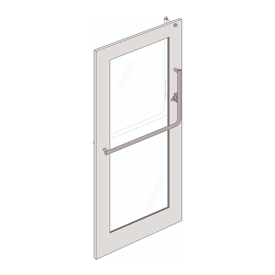
PDU8500 Series Panic Device
IMPORTANT: PLEASE READ BEFORE INSTALLING THE PANIC DEVICE
The following instructions will decrease your chances of experiencing problems during
the installation and ensure a smooth, trouble-free operation of the Panic Device.
Copyright © 2020-2021, ASSA ABLOY Accessories and Door Controls Group, Inc. All rights reserved. Reproduction in whole
or in part without the express written permission of ASSA ABLOY Accessories and Door Controls Group, Inc. is prohibited.
Advertisement
Table of Contents

Related Manuals for Assa Abloy PDU8500 Series


Summary of Contents for Assa Abloy PDU8500 Series
- Page 1 Panic Device. Copyright © 2020-2021, ASSA ABLOY Accessories and Door Controls Group, Inc. All rights reserved. Reproduction in whole or in part without the express written permission of ASSA ABLOY Accessories and Door Controls Group, Inc. is prohibited.
-
Page 2: Table Of Contents
4.3 Mechanical Maintenance ........................15 Copyright © 2020-2021, ASSA ABLOY Inc. All rights reserved. Reproduction in whole or in part without the express written permission of ASSA ABLOY Inc. is prohibited. -
Page 3: Introduction
Introduction Description • The PDU8500 Series Panic Device offers superior functionality for egress and security needs. • Please read the Installation Instructions in this manual carefully before installing the Panic Device. • The PDU8500 installs the same on the following door types: Storefront, Wood and Metal. -
Page 4: Instructions For Storefront, Wood And Metal Doors
Pull the Panic Device away from the Shipping Board by tilting the device. Set Screw Pin Set Screw Screw Pin Panic Device Copyright © 2020-2021, ASSA ABLOY Inc. All rights reserved. Reproduction in whole or in part without the express written permission of ASSA ABLOY Inc. is prohibited. -
Page 5: Remove Horizontal Door Mount
Interior Pivot Bracket Post • Remove Metal Washer, Alignment Bushing and Spacer. Panic Device Set Screws Copyright © 2020-2021, ASSA ABLOY Inc. All rights reserved. Reproduction in whole or in part without the express written permission of ASSA ABLOY Inc. is prohibited. -
Page 6: Remove Actuator Post Assembly
Make the necessary adjustment to get equal spacing between the sides of the Actuator Post Assembly and the tube opening. Copyright © 2020-2021, ASSA ABLOY Inc. All rights reserved. Reproduction in whole or in part without the express written permission of ASSA ABLOY Inc. is prohibited. -
Page 7: Install Mating Pull
"-18) into the Mating Pull Assembly Post until tight. CAUTION: Depending on weatherstripping, extra metal washers provided may be required. Copyright © 2020-2021, ASSA ABLOY Inc. All rights reserved. Reproduction in whole or in part without the express written permission of ASSA ABLOY Inc. is prohibited. -
Page 8: Install Horizontal Door Mount
Door. CAUTION: Depending on weatherstripping, extra metal washers provided may be required. Copyright © 2020-2021, ASSA ABLOY Inc. All rights reserved. Reproduction in whole or in part without the express written permission of ASSA ABLOY Inc. is prohibited. -
Page 9: Install Panic Device On Door
Post Post Panic Device Assembly • Install the Set Screw Pin. Assembly Door Door Copyright © 2020-2021, ASSA ABLOY Inc. All rights reserved. Reproduction in whole or in part without the express written permission of ASSA ABLOY Inc. is prohibited. -
Page 10: Align Actuator Gauge
• Use an Allen Wrench ( ") to rotate in or out as needed. Copyright © 2020-2021, ASSA ABLOY Inc. All rights reserved. Reproduction in whole or in part without the express written permission of ASSA ABLOY Inc. is prohibited. -
Page 11: Installation And Adjustment Of Door Stop-Strike
Copyright © 2020-2021, ASSA ABLOY Inc. All rights reserved. Reproduction in whole or in part without the express written permission of ASSA ABLOY Inc. is prohibited. -
Page 12: Latch Adjustment For Proper Engagement With The Strike
Ceiling Clearance Flat Head Screw (6-32) CAUTION Do not Remove the Screw Figure 3-4 Copyright © 2020-2021, ASSA ABLOY Inc. All rights reserved. Reproduction in whole or in part without the express written permission of ASSA ABLOY Inc. is prohibited. -
Page 13: Cylinder Recommendations
9851-4; 8851-4; E6551-4; 6551-4; 6151-4; L651-4; 651-4 STANLEY/BEST 1E Series C128, C129, C136, C208 Copyright © 2020-2021, ASSA ABLOY Inc. All rights reserved. Reproduction in whole or in part without the express written permission of ASSA ABLOY Inc. is prohibited. -
Page 14: Cleaning And Maintenance
Anodized Copyright © 2020-2021, ASSA ABLOY Inc. All rights reserved. Reproduction in whole or in part without the express written permission of ASSA ABLOY Inc. is prohibited. -
Page 15: Mechanical Maintenance
75.2 in-lb (9 N-m) 132 in-lb (16 N-m) • Periodically, re-lubricate the above components of the device. Copyright © 2020-2021, ASSA ABLOY Inc. All rights reserved. Reproduction in whole or in part without the express written permission of ASSA ABLOY Inc. is prohibited. - Page 16 Architectural Accessories Group Vaughan, ON L4K 4T9 Rockwood, PA 15557 P: 800.461.3007 P: 800.458.2424 Copyright © 2020-2021, ASSA ABLOY Inc. All rights reserved. Reproduction in whole or in part 30072 04/21 without the express written permission of ASSA ABLOY Inc. is prohibited.
Need help?
Do you have a question about the PDU8500 Series and is the answer not in the manual?
Questions and answers