
Related Manuals for Baumer R600V.DAE0-11209335


Summary of Contents for Baumer R600V.DAE0-11209335
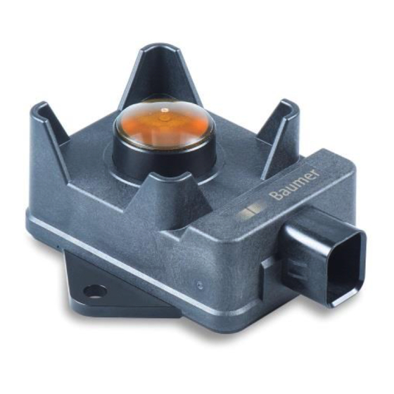
- Page 1 R600V.DAE0 Operating Manual (EN) Off-Highway Ground & Crop Radar Sensor Last Update: 07 Jan 2021 Baumer Electric Hummelstrasse 8501 Frauenfeld, Switzer- land 1/29...
-
Page 2: Table Of Contents
Manual R600V.DAE0 (EN) Table of Contents General Information ......................4 Scope ........................4 Comments, notes, and warnings ................4 Intended Use ......................4 1.3.1 General ......................4 1.3.2 Audience ......................5 1.3.3 Application Policy ....................5 1.3.4 Compliance Statements ..................7 1.3.5 Maintenance ...................... - Page 3 No Warranty ....................27 7.1.3 No Offer ......................27 7.1.4 Limitation of Liability ..................27 7.1.5 Governing Law and Jurisdiction ..............27 Document Revision History ................... 28 Baumer Worldwide ......................29 R600V.DAE0_manual_1.5 (EN).docm Page 3 of 29 Last Update: 07 Jan 2021...
-
Page 4: General Information
Manual R600V.DAE0 (EN) 1 General Information 1.1 Scope This manual is intended for the Baumer “Off-Highway Ground & Crop Radar Sensor” family and contains information about its installation and commissioning. The sensors and their soft- ware configurations are listed below:... -
Page 5: Audience
The manual is written based on current information. Baumer reserves the right to update prod- ucts, documentation and its manuals if better information becomes available. - Page 6 The product shall not be used in the direct control and modification of the state of function of the vehicle. Baumer ensures the compliance of its products to the specifications and declarations of con- formity made available through its website www.baumer.com.
-
Page 7: Compliance Statements
NOTICE: Changes or modifications made to this equipment not expressly approved by Baumer may void the FCC authorization to operate this equipment. NOTE: This equipment has been tested and found to comply with the limits for a Class A digital device, pursuant to Part 15 of the FCC Rules. -
Page 8: Maintenance
Do not dispose of electrical and electronic equipment in household waste. The product con- tains valuable raw materials for recycling, which is why an old product must be returned to an authorised collection point for correct disposal / recycling. For further information refer to www.baumer.com. Page 8 of 29 R600V.DAE0_manual_1.5 (EN).docm... -
Page 9: Integration Guidance
2.1.2 Mounting A mounting plate with a flatness of better than 0.2mm per 100mm shall be used. Baumer recommends soft steel as material to match specified mounting torque. For direct mounting (thread in plate) Baumer recommends a thickness of the steel plate of at least 6mm. For mounting on a thinner soft steel plates (≥3mm) flange nuts must be used instead. -
Page 10: Fig 2 Mounting On Thick Soft Steel Plate (≥6Mm)
Manual R600V.DAE0 (EN) Fig 2 Mounting on thick soft steel plate (≥6mm). Fig 3 Mounting on a thin soft steel plate (≥3mm) It is recommended to use M6 screws per MBM 10105. The mounting torque for 10.9 (property class) screws must be within 12Nm…15Nm, and for 8.8 (property class) screws it must be within 10Nm...12Nm. -
Page 11: Fig 4 Mounting Pattern, Tool Space
Manual R600V.DAE0 (EN) Fig 4 Mounting pattern, tool space. ATTENTION Observe mounting torque and tool space to avoid damage.to sensor. R600V.DAE0_manual_1.5 (EN).docm Page 11 of 29 Last Update: 07 Jan 2021... -
Page 12: Free Space And Directional Sensitivity
2.1.3 Free Space and Directional Sensitivity The Baumer off-highway radar sensor is a very sensitive device to deliver superior crop pen- etration and crop detection performance. The opening angle of the main beam is 6° (for 3dB signal reduction, or approx. 9° for 20dB signal reduction). A typical directional sensitivity is shown below. -
Page 13: Targets And Measurement
Manual R600V.DAE0 (EN) 2.2 Targets and Measurement 2.2.1 Reference Target All data sheet specifications are based on a low-reflectance target (a wood panel with dimen- sions 1200mm by 1700mm). This is to simulate the low reflectance of natural objects while avoiding distance ambiguities. -
Page 14: On Vehicle Calibration
Manual R600V.DAE0 (EN) Directionality (opening angle) Distance averaging Strong re- flections (over opening angle) Fig 7 Shifting reflections in a stationary situation 2.2.3 On Vehicle Calibration In a stationary situation (vehicle is not moving) while measuring on structured surfaces (such as soil) the output distances may shift over time, due to slight changes in position due to vibration and varying radar wave interference. -
Page 15: Electrical Integration
Manual R600V.DAE0 (EN) 2.3 Electrical Integration The sensor can be used on direct vehicle power for 12VDC nominal voltage systems, and 24VDC nominal voltage systems in the range +VS = 9VDC … 32VDC. A centralized load dump suppression (35V at 12VDC, and 58V at 24VDC nominal voltage respectively) is re- quired. -
Page 16: Visual Diagnostic
Manual R600V.DAE0 (EN) ATTENTION The product shall be appropriately protected by an extern fuse or R/C. NOTE For test installations a cable with the order code 11213075 (ZCABL- ALL.AMP0300) may be used. 2.4 Visual Diagnostic High luminosity LEDs provide quick feedback on the operational status of the sensor. The LEDs are positioned behind the radar lens and may be observed even under bright ambient light. -
Page 17: Can Interface (Physical Layer)
Manual R600V.DAE0 (EN) 2.5 CAN Interface (Physical Layer) The CAN physical layer is according to SAE J1939-15 (reduced physical layer). Some base parameters are shown in the table below. Tab 6 CAN Interface Parameter Value Bus Speed 250 kbit / sec (1) Bus Termination External termination Bus Voltage... -
Page 18: Can Protocol
SAE J1939-15 Not all functions listed in the referenced standards have been implemented. The following chapters explain the extent and implemented functions. DBC files can be downloaded from the respective product page on www.baumer.com. 3.1 ISO Name Manufacturer code 343 (Baumer Group) -
Page 19: Address Resolution Sequence
Manual R600V.DAE0 (EN) Default address: 0x80 3.2.3 Address resolution sequence After reset, the device performs the following start-up sequence: After initialization, send “request for address claimed” message (PGN 0xEE00) At initialization, clear the address sort table Send a request for address claimed. This causes other devices on the bus to claim their addresses Wait 1250 ms. -
Page 20: Supported Pgn (Parameter Group Number)
Manual R600V.DAE0 (EN) 3.3 Supported PGN (Parameter Group Number) 3.3.1 ECU Identification Info PGN: 0xFDC5 Direction: Transmit Transmission rate: On PGN request only 3.3.2 ECU Software Identification PGN: 0xFEDA Direction: Transmit Transmission rate: On PGN request only 3.3.3 DM14 Memory access command message PGN: 0xD900 Direction:... -
Page 21: Vehicle Speed Message (Reserved)
Manual R600V.DAE0 (EN) Tab 9 Ground & Canopy Message Start bit Bits Offset Scaling Description Sensor status 0 = No error 1 = Reversible error. (e.g. temperature too high) 2 = Irreversible error. Sensor measurement not available Canopy confidence (3) Value 0…100% (higher confidence = detection of canopy better) Ground confidence (3) -
Page 22: Exemplary Decoding Of A Can Message Frame
Manual R600V.DAE0 (EN) 3.4 Exemplary Decoding of a CAN message frame Exemplary decoding the “ground & canopy” message (PGN 0xC000) Based on a line from a CAN log (6339707, 18C0FF80, Rx, 8, 8C, AB, 27, C, 34, C, 0, 0) Tab 11 Decoding a CAN SAE J1939 message frame 0…8 byte 11 bit CAN ID... -
Page 23: Sensor Configuration
Manual R600V.DAE0 (EN) 3.5 Sensor Configuration A number of sensor parameters can be read and written over the CAN bus using the J1939 memory access (MA) protocol. User level for access = 1 Key for access is equal to the “seed” generated by the device. All addresses are direct spatial (is pointer) The access is similar to the SPN space. -
Page 24: Trouble Shooting
Manual R600V.DAE0 (EN) 4 Trouble Shooting Tab 15 Trouble Shooting Overview Failure Action No function, no LED Check cables, connections, power supply at pins Function impaired, thick layer of dirt Clean lens and remove excess water. Mechanical damage to housing Replace part by qualified personnel. -
Page 25: Appendix
Manual R600V.DAE0 (EN) 6 Appendix 6.1 Table Overview Tab 1 Applicable Products ....................4 Tab 2 Applicable Documents ....................7 Tab 3 Connector Pin-Out ....................15 Tab 4 Vehicle Power Electrical Transients ............... 15 Tab 5 Status Mapping (Visual Diagnostic) ................ 16 Tab 6 CAN Interface ...................... -
Page 26: Definitions And Abbreviations
Manual R600V.DAE0 (EN) 6.3 Definitions and Abbreviations The following definitions and abbreviations are used throughout this manual Tab 17 Definitions and Abbreviations Definition Acknowledgement (CAN message frame) Controller Area Network Cyclic redundancy check Destination address Data Sheet Data length code (CAN message frame) Direct Memory Electronic Control Unit End of frame (CAN message frame) -
Page 27: Terms And Conditions Of Use
7.1.1 Copyright The entire content of this manual is protected by copyright law. All rights remain reserved to the Baumer Group. The printout of this manual is permitted provided that neither the copyright statements nor any other legally protected designations are removed or altered. The (complete or partial) reproduction, transmission, modification, linking or utilization of this manual for publishing or commercial goals is pro- hibited without prior written approval from the Baumer Group. -
Page 28: Document Revision History
Manual R600V.DAE0 (EN) 8 Document Revision History Tab 18 Document revision history Vers. Date Note Author Checked Released tip, matts, rma, 29 Oct 2019 Technical review wemi 15 Nov 2019 Initial Release wemi lph, sfri 1.01 28 Nov 2019 Fix addresses for settings wemi 29 Nov 2019 Align with other documents... -
Page 29: Baumer Worldwide
Manual R600V.DAE0 (EN) 9 Baumer Worldwide Belgium Brasil Canada Baumer SA/NV Baumer do Brasil Ltda Baumer Inc. BE-2260 Westerlo 13208-120 Jundiaí, São Paulo CA-Burlington, ON L7M 4B9 Phone +32 14 57462 0 Phone +55 11 4523-5120 Phone +1 (1)905 335-8444...
Need help?
Do you have a question about the R600V.DAE0-11209335 and is the answer not in the manual?
Questions and answers