Table of Contents
Advertisement
Quick Links
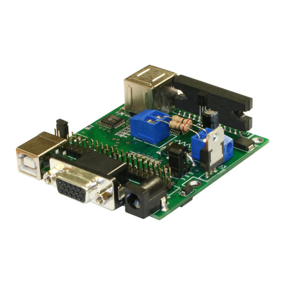
8SMC1-USBhF
1.5A Microstep Driver with USB Interface
User Manual
Note: Information in this manual is believed to be accurate and reliable. However no responsibility is assumed
for the consequences of its use or for any infringement of patents or other right of third parties which may
result from it use. Specifications are subject to change without notice.
Note: Windows are registered trademark of Microsoft Corporation, LabVieW and NI VISA is registered
trademark of National Instruments Inc. All other products and corporate names appearing in this manual may
or may not be registered or copyrights of their respective companies, and are used only for identification or
explanation and to the owner's benefit, without intent to infringe.
1/14/2008
www.standa.lt
Page 1 of 83
Advertisement
Table of Contents

Related Manuals for Standa 8SMC1-USBhF


Summary of Contents for Standa 8SMC1-USBhF
- Page 1 8SMC1-USBhF 1.5A Microstep Driver with USB Interface User Manual Note: Information in this manual is believed to be accurate and reliable. However no responsibility is assumed for the consequences of its use or for any infringement of patents or other right of third parties which may result from it use.
-
Page 2: Table Of Contents
First start on Windows XP ....................35 First start on Windows Vista ....................37 Switching between NI VISA and MicroSMC drivers on Windows XP ......38 Switching between NI VISA and MicroSMC drivers on Windows Vista ......40 1/14/2008 www.standa.lt Page 2 of 83... - Page 3 Get State (uSMC)......................63 6.1.9 Get Version (uSMC) ......................64 6.1.10 Start (uSMC) ........................64 6.1.11 Stop (uSMC) ........................64 6.1.12 Load Profile (uSMC)......................64 6.1.13 Update Speed Ctl (uSMC)....................64 Structures..........................64 6.2.1 Mode ..........................64 6.2.2 Parameters........................65 6.2.3 State..........................67 6.2.4 StartPlus .........................67 1/14/2008 www.standa.lt Page 3 of 83...
- Page 4 USMC_EncoderState.....................81 Examples..........................81 7.7.1 C++ example ........................81 Dynamic link library USMCDLL.dll for WM ................82 General information......................82 File list ............................82 8.2.1 Host PC files........................82 8.2.2 Mobile device files......................82 Functions..........................83 Test Applications........................83 Examples..........................83 8.5.1 C++ example ........................83 1/14/2008 www.standa.lt Page 4 of 83...
-
Page 5: General Information
Set of virtual instruments for National Instruments LabVieW 1.2 Description The 8SMC1-USBhF controller is designed to drive one bipolar stepping motor by local and/or remote means. Local control and indication are implemented by two knobs and three LEDs. Remote control and monitoring are implemented via USB interface from PC. Inputs for two limit switches, emergency switch and revolution sensor are provided. -
Page 6: Applications
8SMC1-USBhF boards: it possible to connect 8SMC1-USBhF board to each of two free downstream USB ports on another 8SMC1-USBhF board. Thus, it is possible to connect up to 30 devices per USB host controller in tree-like structure without any additional USB hubs. -
Page 7: Functional Description
The Power driver IC fin (rear) is electrically connected to the rear of the chip. When current flows to the fin, the Power driver IC malfunctions. If there is any possibility of a voltage being generated between the ground of the 8SMC1-USBhF and the fin, either ground the fin or insulate it. - Page 8 USB Out - Two USB type A connectors are placed on the rear of 8SMC1-USBhF printed circuit board. It allows the connection of other USB devices or lower USB hubs. - Enable/Disable Emergency stop switch jumper, see Figure 3 and Figure 4.
- Page 9 If you want to change the power logic jumper position make the following steps: Turn the power of 8SMC1-USBhF board OFF, unplug the USB In connector, change the JP2 position, turn the power of 8SMC1-USBhF board ON and plug USB In connector back.
-
Page 10: External Connections
2.2.1.1 USB Powered logic mode In this case logic of 8SMC1-USBhF board is powered by USB; stepper motor is powered by external 7-40V stabilized DC power supply. Connection diagram for Power In is shown on Figure 12, for multi-purpose 40 pin connector P1 on Figure 13. Correct position of board logic power supply jumper (JP2) is shown on Figure 6. -
Page 11: Dc Powered Logic Mode
2.2.1.3 Single 7-12V DC power supply mode In this case logic of 8SMC1-USBhF board and stepper motor is powered by single 7-12V DC power supply. Correct position of board logic power supply jumper (JP2) is shown on Figure 8. Connection diagram for powering through multi-purpose 40 pin connector P1 is shown on Figure 15. -
Page 12: Double Power Supply Mode
2.2.1.4 Double power supply mode In this case logic of 8SMC1-USBhF board is powered by external 7-12V DC power supply; stepper motor is powered by external 7-40V stabilized DC power supply. Correct position of board logic power supply jumper (JP2) is shown on Figure 8. Connection diagram for multi-purpose 40 pin connector P1 is shown on Figure 17. -
Page 13: Connection Of External Sensors
2.2.3 Connection of external sensors All external sensors (limit switches, emergency limit switch, revolution sensor and knobs) are connected to 8SMC1-USBhF by the same way. There are several different possibilities of connection for every sensor. Farther we examine these possibilities more accurately. -
Page 14: Limit Switches
It can be programmed as normally opened or closed contact. It can be enabled or disabled by software (see 5.4.10). Also it is possible to swap limit switches by the software. Limit switches are connected to 8SMC1-USBhF according to 2.2.3. Controller inputs for each limit switch are shown on Table 2. -
Page 15: Emergency Stop Switch
Figure 26. Connection Emergency Stop switch to Stepper motor connector 2.2.6 Revolution sensor Revolution sensor is intended for stepper motor stall detection. 8SMC1-USBhF can receive data about the real position of stepper motor shaft from Revolution sensor. Latter is an external sensor (see 2.2.3) that joins directly to stepper motor shaft and change electrical state several times per stepper motor shaft revolution. -
Page 16: Encoder
Connection diagram of encoder to multi-purpose 40 pin connector P1 is shown on Figure 30, to Stepper motor connector is shown on Figure 29. Figure 27. Electrical signal on CH A and CH B outputs of quadrature encoder 1/14/2008 www.standa.lt Page 16 of 83... - Page 17 Note: For correct work of encoder at high speed it is necessary to use special version of 8SMC1-USBhF controller board. Ask this option your local dealer. 1/14/2008 www.standa.lt Page 17 of 83...
-
Page 18: Synchronization Out
2.2.8 Synchronization Out 8SMC1-USBhF can serve as an external synchronization for other devices. It can produce TTL output pulse every N steps, where N is controlled by software. It is usually used for starting some repeated action like a routine measurement. -
Page 19: Manual Control Knobs
“Down” and “Status”. LED "Up” blinks when stepper motor is moving "Up” (step counter in 8SMC1-USBhF is incremented) and light if Limit switch 1 is reached (or Limit switch 2, if Swap Limit switches option is enabled). LED "Down” blinks when stepper motor is moving "Down”... -
Page 20: Usb In/Out
USB In (USB type B connector) is used for connection with computer or higher USB hub. Embedded 3-port USB hub allows cascading of the 8SMC1-USBhF boards. USB Out (two USB type A connectors) allow the connection of other USB devices or lower USB hubs to this 8SMC1-USBhF board. -
Page 21: Specifications
2-5000 step/s Position counter -2.147.483.647 – 2.147.483.647 Accel and decel ramps programmable Soft start/stop mode programmable 3.3 Remote control Communication Protocol USB 1.1 Communications baud rate up to 12 Mbps Max devices per USB host 1/14/2008 www.standa.lt Page 21 of 83... -
Page 22: Mechanical
3.4 Mechanical Dimensions of 8SMC1-USBhF are shown below. Operating temperature range: 0-70 °C. Heatsink (see Figure 37) may be required to maintain temperature range. Figure 36. Dimensions of 8SMC1-USBhF board Figure 37. Heatsink for 8SMC1-USBhF 1/14/2008 www.standa.lt Page 22 of 83... -
Page 23: Wiring Diagram
On Figure 38 three different power supplies are shown. Only two or one power supply is needed of course. Choose a convenient way of power supply connection according to 2.2.1. For more details see Functional description (Chapter 2). 1/14/2008 www.standa.lt Page 23 of 83... -
Page 24: Wiring Diagram For Stepper Motor Connector
Figure 39. Wiring diagram for Stepper motor connector 3.6 EMC 8SMC1-USBhF 1.5A Microstep Driver with USB Interface conforms to electromagnetic immunity requirements listed in LST EN 61000-6-2:2002 for industrial environments in accordance with standards LST EN 61000-4-2+A1+A2:2002, LST EN 61000-4-4:2002, LST EN 61000-4-4/A1:2002, LST EN 61000-4-4/A2:2002. -
Page 25: Installation
Hardware installation of 8SMC1-USBhF controller (see 4.2). o First start (see 4.3). If it is supposed to program 8SMC1-USBhF controller on C, C++, Basic, Delphi, MatLab or other languages exclude LabVieW install MicroSMC driver (see paragraph 4.1.2). If it is supposed to control 8SMC1-USBhF using mobile devices working under Microsoft Windows Mobile 5.0 and higher install MicroSMC for WM driver (see paragraph 4.1.3). - Page 26 Please wait while the installer initializes (see Figure 41). Figure 42. SMCVieW 3 installation screen o Select destination folders and press the “Next>” button (see Figure 42). Figure 43. SMCVieW 4 installation screen 1/14/2008 www.standa.lt Page 26 of 83...
-
Page 27: Microsmc Driver Installation
4.1.2 MicroSMC driver installation Note: Install MicroSMC driver if suppose to program 8SMC1-USBhF controller in C, C++, Basic, Delphi, MatLab or other languages excluding LabVieW. For LabVieW based applications, for example SMCVieW, only NI VISA driver is necessary. - Page 28 Open MicroSMC folder on 8SMC1-USBhF installation disk. And click on setup.exe file. Next screen will be shown (see Figure 46). Then press “Next>” button. o On the next screen (see Figure 47) choose installation folder and press “Next>” button.
- Page 29 Read brief instructions on using the MicroSMC driver and dll (see Figure 50). Figure 49. MicroSMC 4 installation screen Figure 50. MicroSMC 5 installation screen Figure 51. MicroSMC last installation screen o Press “Close” to complete the installation (see Figure 51). 1/14/2008 www.standa.lt Page 29 of 83...
-
Page 30: Microsmc For Wm Installation
4.1.3 MicroSMC for WM installation MicroSMC for WM is a USB host driver for 8SMC1-USBhF controllers for mobile devices. It is designed for control and monitor 8SMC1-USBhF controllers using mobile devices with Microsoft Windows Mobile 5.0 or higher operation system. Only presence a USB host port on your mobile device is necessary. - Page 31 Read carefully this screen (see Figure 53) and press the “Next>” button. Figure 54 MicroSMC for WM host PC installation 3 screen o Select destination folder and press the “Next>” button (see Figure 54). Figure 55. MicroSMC for WM host PC installation 4 screen 1/14/2008 www.standa.lt Page 31 of 83...
- Page 32 After the previous step (see Figure 56) ActiveSync Application Manager window will appear (see Figure 57). If nothing happens navigate on host PC to MicroSMC for WM installation folder (usually C:\Program WM\) and run Files\MicroSMC CEAppMgrSetup.exe application. 1/14/2008 www.standa.lt Page 32 of 83...
- Page 33 System -> Remove programs, pick MicroSMC for WM and click Remove. One other way: on host PC right click on Microsoft ActiveSync icon in system tray, choose Open Microsoft ActiveSync. Navigate Tools -> Add/Remove Programs, pick MicroSMC and click Remove. 1/14/2008 www.standa.lt Page 33 of 83...
-
Page 34: Hardware Installation
Read chapter 2 before hardware installation! Make sure that power of 8SMC1-USBhF is off. Verify that current sense resistors on 8SMC1-USBhF board match the rated current that is supposed to be used with stepper motor. Change resistors if necessary (see 2.1 and 4.2.1). -
Page 35: First Start On Windows Xp
The main window of Hardware Wizard will be appeared (see Figure 60). Choose ”No, not this time” and press the “Next>” button. On some old version of WindowsXP this screen may be skipped. 1/14/2008 www.standa.lt Page 35 of 83... - Page 36 Wait until installation will be done (see Figure 62) and press “Finish” button (see Figure 64). Figure 63. Hardware wizard 4 screen o If other 8SMC1-USBhF controllers were installed on computer earlier, screen Figure 63 may appear. Choose 8SMC1-USB.inf and press “Next” button. 1/14/2008 www.standa.lt...
-
Page 37: First Start On Windows Vista
Make sure that the emergency stop jumper is set in OFF position (see 2.1 and 2.2.5). Note: If you disconnect the USB cable of 8SMC1-USBhF and connect it again to another USB port then installation of 8SMC1-USBh driver may be required once more. In this case choose “Install software automatically”. -
Page 38: Switching Between Ni Visa And Microsmc Drivers On Windows Xp
4.5 Switching between NI VISA and MicroSMC drivers on Windows XP All 8SMC1-USBhF boards that have connected to PC can work either with NI VISA driver or MicroSMC driver. It is possible to install on PC several drivers for one class of USB devices... - Page 39 USB driver at a time. Therefore if 8SMC1-USBhF board is connected to PC using, for example, MicroSMC driver then it will not be accessible for applications that use NI VISA driver and vice versa. For switching from NI VISA to MicroSMC driver please do the following: o Open Device Manager (choose My Computer then right click->Properties->Hardware-...
-
Page 40: Switching Between Ni Visa And Microsmc Drivers On Windows Vista
(NI VISA driver and MicroSMC driver, for example) but every particular 8SMC1-USBhF board can work only with one USB driver at a time. Therefore if 8SMC1-USBhF board is connected to PC using, for example, MicroSMC driver then it will not be accessible for applications that use NI VISA driver and vice versa. - Page 41 Figure 71. Uninstallation of NI VISA USB driver o Then disconnect USB cable of 8SMC1-USBhF controller and connect it again. When Hardware Wizard will found new hardware and offer you to install driver skip it choosing “Don't show this message again for this device” option (see Figure 72).
- Page 42 At the next screen choose ”Browse my computer for driver software” (see Figure 74). Figure 74. Browse my computer for driver software. o Choose the folder with MicroSMC driver, ”C:\Program Files\MicroSMC\Driver” usually, and press “Next” (see Figure 75). 1/14/2008 www.standa.lt Page 42 of 83...
- Page 43 MicroSMC driver (see Figure 71). Choose the folder with VISA driver, ”C:\Program Files\SMCVieW\Drivers” usually, on Figure 75. Note that in Device Manager list MicroSMC driver is placed in “Universal Serial Bus controllers” group (see Figure 77). 1/14/2008 www.standa.lt Page 43 of 83...
- Page 44 “Install the software automatically (Recommended)” mode (see Figure 61) may works improper if more than 6 8SMC1-USBhF devices are connected. In case of that improper work Hardware wizard has been looking for USB driver several minutes and find nothing, USB driver will not be installed and 8SMC1-USBhF controller will mark with “?”...
- Page 45 Use this way always when you are installing a lot of 8SMC1-USBh devices: choose at screen like Figure 61 “Install from a list or specific location (Advanced)” and “Don’t search. I will choose the driver to install” then. 1/14/2008 www.standa.lt Page 45 of 83...
- Page 46 Figure 81. Screen with four devices is shown on Figure 82. Interface can represent up to three devices simultaneously. If more than three 8SMC1-USBhF devices are used at the same time, slider is displayed at the left side of SMCVieW interface (see Figure 82).
- Page 47 Figure 82. SMCVieW main screen. Four 8SMC1-USBhF drives found 5.2.2 Positioners and axes names On left top of the main window positioner model is shown (see 83). It can be changed by Setup (see 5.4.2). Under the positioner model box the lettering of axis is shown (see 83).
- Page 48 Indicator Temperature shows the temperature of Power driver of 8SMC1-USBhF controller in Celsius. Indicator Voltage shows the voltage on Power driver of 8SMC1-USBhF controller. Indicator Power shows the stepping motor power. Possible values: None - stepping motor is not powered, HALF - stepping motor in hold mode, 40% current reduction, FULL –stepping motor is fed by full power.
- Page 49 SMCVieW main menu consists of three submenus: Extra, Encoder and Help. Menu Extra contains additional applications that can be used if you have special license. Contact you dealer for additional information. Menu Encoder contains special widows that show current shaft position (see Figure 89). 1/14/2008 www.standa.lt Page 49 of 83...
- Page 50 Buttons are shown in Figure 90. Save params – saves current installation-specific settings on disk. Load params – loads current installation-specific settings from disk. Save to flash – saves current installation-specific settings on 8SMC1-USBhF flash memory. Default – restore default installation-specific settings.
- Page 51 This window shows the view of selected positioner. 5.4.4 Positioner -> Wiring This window shows the selected wiring diagram. Use this field for information purposes only. Make sure that real wiring diagram is equal to this (see 3.5 for more information). 1/14/2008 www.standa.lt Page 51 of 83...
- Page 52 Figure 93. Setup screen “Positioner -> Wiring” 5.4.5 Controller identifier Figure 94. Setup screen “Controller identifier” Step motor driver identifier - the unique numerical identifier of this 8SMC1-USBhF driver. Axis name - Lettering of this axis. Version - Version of controller firmware.
- Page 53 Buttons disabled – This check box disables or enables buttons for local control. Reset timeout, ms - Pressing of two buttons and holding during this timeout leads to reset driver and shifting to null position (in ticks). Possible value 1..9961 ms. 1/14/2008 www.standa.lt Page 53 of 83...
- Page 54 Positioner's Type – type of positioner. Possible values: Rotational or Linear. Major difference: linear positioner has two limit switches and its working range locates between it, rotational stage has only one switch that correspond to zero position. 1/14/2008 www.standa.lt Page 54 of 83...
- Page 55 See Figure 99. It is possible to disable limit switches and choose pushed position. Also it is possible to swap limit switches. Figure 99. Limit switches setup screen 5.4.11 Revolution sensor Revolution sensor is intended for sense stepper motor slipping and inform user if slipping is detected. 1/14/2008 www.standa.lt Page 55 of 83...
- Page 56 ErrorVal) Error will be lighted up just after the next start. Radio button on Figure 101 determines encoder state: Disabled, Normal Polarity and Reversed Polarity. Normal and reversed polarity define the direction of encoder incrementing 1/14/2008 www.standa.lt Page 56 of 83...
- Page 57 0. This button is used for setting suitable Current position before starting work with encoder. Figure 101. Encoder setup screen 5.4.13 Synchronization Figure 102. Synchronization setup screen 1/14/2008 www.standa.lt Page 57 of 83...
- Page 58 Current position in units - setting new current position in units. This control is usually used for calibrating if you want to assume current position defined value in units. Use button Set for calibrating and recalibrating. 1/14/2008 www.standa.lt Page 58 of 83...
- Page 59 64 tics. Loft last stage speed - speed of backlash compensation, possible value: 1..625 full steps/s. Carry out backlash Compensation – press this button to carry out backlash Compensation. Figure 104. Backlash compensation setup screen 1/14/2008 www.standa.lt Page 59 of 83...
- Page 60 Maximum speed, units/sec - high speed limit (in units/s). Please check this value after recalibration. 5.4.17 Safety On this tab you can set the Thermal power off threshold. Upon reaching this temperature controller will turn off the power. 1/14/2008 www.standa.lt Page 60 of 83...
- Page 61 Figure 106. Thermal power off setup screen 1/14/2008 www.standa.lt Page 61 of 83...
- Page 62 Note: Makes sure that you use 8SMC1-USBh controllers with firmware usmc2503.usm or higher! In other case update it before programming (see paragraph 5.4.5). Note: Makes sure that you use NI LabVIEW 7.1.1 or higher. 1/14/2008 www.standa.lt Page 62 of 83...
- Page 63 Serial Number – unique identifier of the controller 6.1.8 Get State (uSMC) Gets information about the current state of the specified controller Current State – cluster described at the section 6.2.3 on page 67. 1/14/2008 www.standa.lt Page 63 of 83...
- Page 64 Emergency Power FALSE Power will be off without moving to the whole step position. As the result accurate position will be lost. Limit switch 1 True FALSE Limit switch 1 true logical state 1/14/2008 www.standa.lt Page 64 of 83...
- Page 65 Reset SM Enc Pos to FALSE Sets current step motor position (in encoder units) to Enc Pos encoder position. 6.2.2 Parameters Title Default Description Acceleration Time [u16] Acceleration time (in ms). Possible range: 1 - 24990. 1/14/2008 www.standa.lt Page 65 of 83...
- Page 66 Sync duration [u16] - Duration of the output synchronization pulse in steps (or microsteps, depending on resolution) between the output synchronization pulses. Loft Speed [u16] - Speed of the last phase of the backlash operation. 1/14/2008 www.standa.lt Page 66 of 83...
- Page 67 They are used at the SMCVieW application and can be imported with the help of “Load Profile (uSMC).vi. 1/14/2008 www.standa.lt Page 67 of 83...
- Page 68 R, Ohm [dbl] – value of the current sense resistors that should be used in the controller I, mA [dbl] – minimal current, required for proper rotation of stepper motor or positioner 1/14/2008 www.standa.lt Page 68 of 83...
- Page 69 Maximal Value 33554427.78 [dbl] – Maximal value that can be achieved with current experimental set-up in the units of the real world 6.3 Examples See Examples on CD in \Development Kit\VIs folder. 1/14/2008 www.standa.lt Page 69 of 83...
- Page 70 USMCDLL.dll – Windows dynamic link library containing all functions used to control step motor. It is placed in %win%/%sys32% directory %MicroSMC%\USMCDLL.lib – “lib” file, describing DLL functions, which can be used as input to linker %MicroSMC%\USMCDLL.h – C/C++ header file with functions and structures declarations 1/14/2008 www.standa.lt Page 70 of 83...
- Page 71 Error code USMC_Init USMC_Devices Error code USMC_GetState USMC_State Error code USMC_SaveParametersToFlash SETUP/OUT Error code USMC_SetCurrentPosition SETUP/OUT Error code USMC_GetMode – USMC_Mode Error code USMC_SetMode USMC_Mode Error code USMC_GetParameters – USMC_Parameters Error code USMC_SetParameters USMC_Parameters 1/14/2008 www.standa.lt Page 71 of 83...
- Page 72 DWORD USMC_GetState( DWORD Device, USMC_State &Str ); Argument list: – IN – Device number DWORD Device – OUT – Structure describing current device state USMC_State &Str 1/14/2008 www.standa.lt Page 72 of 83...
- Page 73 Zero value for normal execution and nonzero value otherwise. Remarks: USMC_Mode structure is filled with values last sent by the USMC_SetMode function or with default values for this device. Default values can be changed to the desired 1/14/2008 www.standa.lt Page 73 of 83...
- Page 74 7.5.7 USMC_SetMode USMC_SetMode function is used to send device parameters contained in USMC_Mode structure to 8SMC1-USBhF controller. DWORD USMC_SetMode( DWORD Device, USMC_Mode &Str ); Argument list: – IN – Device number DWORD Device – IN/OUT – Structure containing some of parameters (see 7.6.4 USMC_Mode &Str...
- Page 75 7.5.10 USMC_GetStartParameters USMC_GetStartParameters function returns USMC_StartParameters structure last sent to device by means of calling USMC_Start function or default structure. DWORD USMC_GetStartParameters( DWORD Device, USMC_StartParameters &Str ); Argument list: 1/14/2008 www.standa.lt Page 75 of 83...
- Page 76 Any call to this function when step motor is rotating causes it to stop immediately and only then perform requested start operation. 7.5.12 USMC_Stop USMC_Stop function stops the step motor if it is rotating. 1/14/2008 www.standa.lt Page 76 of 83...
- Page 77 When one turns step motor’s power off, it makes minimal required rotation to the nearest “zero–state”. Because of that if maintaining of the step motor’s precise position is required one should follow procedure described above (or just use SMCVieW). 1/14/2008 www.standa.lt Page 77 of 83...
- Page 78 Return value: USMC_GetLastErr function has no return values. Remarks: USMC_GetLastErr function fills the buffer with null terminated string (if length is enough). Don’t forget to allocate corresponding (to argument) amount of memory. 1/14/2008 www.standa.lt Page 78 of 83...
- Page 79 Speed (steps/sec) after BTIMEOUT1 time has passed (see 5.4.8 at page 54) float BTO2P Speed (steps/sec) after BTIMEOUT2 time has passed (see 5.4.8 at page 54) float BTO3P Speed (steps/sec) after BTIMEOUT3 time has passed (see 5.4.8 at page 54) 1/14/2008 www.standa.lt Page 79 of 83...
- Page 80 If TRUE output synchronization counter will be reset Synchronization input mode: TRUE - Step motor will move one time to the DestPos BOOL SyncINOp – FALSE - Step motor will move multiple times by DestPos microsteps as distance 1/14/2008 www.standa.lt Page 80 of 83...
- Page 81 This sample program is written on C++ language as console application. It demonstrates usage of all described functions. Moreover for all members of all structures there is a detailed description in form of formatted string output with function “printf”. 1/14/2008 www.standa.lt Page 81 of 83...
- Page 82 8 Dynamic link library USMCDLL.dll for WM 8.1 General information DLL is designed for control and monitor 8SMC1-USBhF controllers using mobile devices with Microsoft Windows Mobile 5.0 or higher operation system. It includes all basic commands for stepping motors control. Using it, one can write his own programs for Windows Mobile to control 8SMC1-USBhF controllers.
- Page 83 Windows XP. It description see in chapter 7. 8.4 Test Applications There are two test applications in this package for control 8SMC1-USBhF with mobile devices. It is placed in %MicroSMC%\ folder on your mobile device. USMCTest.exe demonstrates general possibilities of USMCDLL.dll, USMCPresentation.exe is a complete application for cycle motion of motorized translation stage with two limit switches.
Need help?
Do you have a question about the 8SMC1-USBhF and is the answer not in the manual?
Questions and answers