Siemens RAJA+ Installation, Maintenance & Troubleshooting Manual
Agriculture starters & controllers
Hide thumbs
Also See for RAJA+:

Related Manuals for Siemens RAJA+


Summary of Contents for Siemens RAJA+
- Page 1 Installation, Maintenance & Troubleshooting Guide For RAJA Agriculture Starters & Controllers...
-
Page 2: Table Of Contents
Contents: 2. Fully Automatic Star Delta Starter: 2.1 Product description 2.2 Wiring diagram 2.3 Technical Details 2.4 Installation 2.5 Operating procedure in normal condition 2.6 Troubleshooting guidelines in case any incoming fault is present before switching ON the motor 2.7 Troubleshooting guidelines in fault condition when motor stops while it is in running condition 2.8 Troubleshooting guidelines in case any fault is at the load side... -
Page 3: Product Description
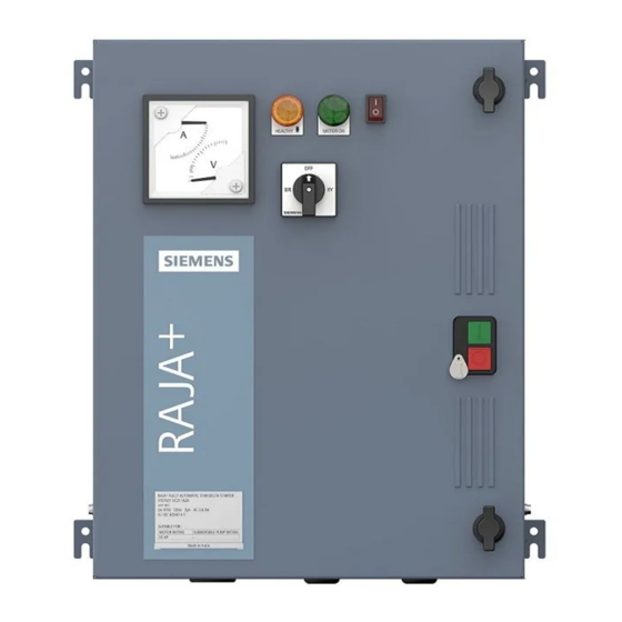
Installation, Maintenance & Troubleshooting guide | Version 02 Product Fully Automatic Star Delta Starter 2.1: Product description 1. ‘ON’ push button (green) 2. ‘OFF/RESET’ push button (red) 3. Door knob 4. Metal Enclosure 5. Door 6. Mechanical Latch (OFF push button) to be used for preventing undesired ON operation of Starter 7. - Page 4 Installation, Maintenance & Troubleshooting guide | Version 02 Inside view of FASD-1 Starter 1: Phase selector switch 10: Thermal overload relay 2: Green LED 11: Star contactor 3: Amber LED 12: Terminal block TB3 4: AV Meter 13: Terminal block TB2 5: Star Delta Timer, 14: Terminal block TB1 6: Starter operating mode...
-
Page 5: Wiring Diagram
Installation, Maintenance & Troubleshooting guide | Version 02 2.2: Wiring Diagram: FASD-1... - Page 6 Installation, Maintenance & Troubleshooting guide | Version 02 Control logic diagram...
- Page 7 Installation, Maintenance & Troubleshooting guide | Version 02 Power circuit diagram...
- Page 8 Installation, Maintenance & Troubleshooting guide | Version 02 Wiring Diagram: FASD-2...
- Page 9 Installation, Maintenance & Troubleshooting guide | Version 02 Control logic diagram...
- Page 10 Installation, Maintenance & Troubleshooting guide | Version 02 Power circuit diagram...
- Page 11 Installation, Maintenance & Troubleshooting guide | Version 02 Wiring Diagram: FASD-3...
- Page 12 Installation, Maintenance & Troubleshooting guide | Version 02 Control logic diagram...
- Page 13 Installation, Maintenance & Troubleshooting guide | Version 02 Power circuit diagram...
-
Page 14: Technical Details
Installation, Maintenance & Troubleshooting guide | Version 02 2.3: Technical details Table: 8 Technical details-FASD starter Star Nominal Type (HP / Line & Overload Range Line Max. conta- HRC fuses Delta Relay Monitoring Recommended ctor rating Contactor Relay^ Cu cable Type Type Type... -
Page 15: Installation
Installation, Maintenance & Troubleshooting guide | Version 02 2.4: Installation • Open the door by rotating the door lock anticlockwise. • Mount the starter on a vertical wall/ plate free from vibrations with proper nuts and bolts. Refer operating instruction for mounting dimensions. •... - Page 16 • If the relay trips even when set at rated motor current the suitability of the starter/relay for the particular application should be checked with the nearest Siemens office. Operating Characteristics: The given characteristics (Fig. 6) are average values of all ranges and sizes of bimetal relays and are mainly intended to indicate the inverse time current characteristics &...
- Page 17 Installation, Maintenance & Troubleshooting guide | Version 02 Table: 9 Mounting torque values Sr. No Location Size Torque LMR-A 0.8-1.1Nm Contactor 3TS30…36 0.8-1.1Nm Contactor 3TS 47/48 0.8-1.1Nm Contactor 3TS 50 /51 1.5-2.0Nm Terminal block 30A 0.8-1.1Nm Terminal block 60A 0.8-1.1Nm Terminal block 100A 0.8-1.1Nm 3RP Timer...
-
Page 18: Operating Procedure In Normal Condition
Installation, Maintenance & Troubleshooting guide | Version 02 2.5: Operating procedure in normal condition Table: 11 FASD starter operating sequence in normal condition LMR-A 3 main Rocker Amber Amber ‘ON’ Push Starter Starter Mode supply switch Delay button Operation Operation Blink Manual (On-delay... - Page 19 Installation, Maintenance & Troubleshooting guide | Version 02 LMR-A: Auto mode 4B : Switch ON the 3-Phase incoming main supply. 4C : Switch ON the rocker switch. 4D : Amber LED will start blinking for a period of min 30sec. 4E : 30sec is the default setting which can vary from min 0.5min to max.5min.
-
Page 20: Troubleshooting Guidelines In Case Any Incoming
Installation, Maintenance & Troubleshooting guide | Version 02 2.6: Troubleshooting Guidelines in case any incoming supply fault is present before switching ON the Starter Table: 12 FASD starter operating sequence in fault condition Possible LMR-A Rocker Amber Amber Corrective Amber ‘ON’... - Page 21 Installation, Maintenance & Troubleshooting guide | Version 02 If fault still exists, then 5G : - Check the rated operational voltage of the starter in incoming terminal block (TB1) between L1-L2, L2-L3, L1-L3 with suitable equipment e.g. multimeter. - Check whether the 3-phase voltage in the incoming terminals of terminal block TB1 is >Maximum voltage allowed. (Refer table no.13).
-
Page 22: Troubleshooting Guidelines In Fault Condition When
Installation, Maintenance & Troubleshooting guide | Version 02 2.7: Troubleshooting Guidelines in fault condition when motor stops while it is in running condition Table: 14 FASD starter operating sequence in fault condition Motor Amber Possible Corrective 3 main Amber Amber ‘ON’... -
Page 23: Troubleshooting Guidelines In Case Any Fault Is At The Load Side
Installation, Maintenance & Troubleshooting guide | Version 02 2.8: Troubleshooting Guidelines in case any fault is at load side Steps to be followed Thermal overload relay provide protection from: a) overload condition at Motor b) single phasing at load side a) overload condition at Motor: check the suitable Motor current rating and adjust the overload relay setting dial as per the requirement. - Page 24 It helps our customers to thrive, communities to progress and supports sustainable development to protect our planet for the next generation. Creating environments that care. siemens.com/smart-infrastructure Published by Siemens Ltd Smart Infrastructure Electrical Products R&D Building, 48, Thane-Belapur Road Thane 400708, India Article no.