Table of Contents
Advertisement
6810560/2
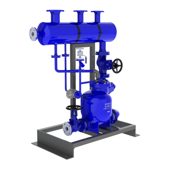
Automatic Packaged Pump Units
Installation and Maintenance Instructions
Triplex MFP14-PPU shown
IM-P681-02 ST Issue 2
MFP14-PPU (Vented)
1. Safety information
2. General
product information
3. Single MFP14 - PPU
installation and
commissioning
4. Duplex MFP14 - PPU
installation and
commissioning
5. Triplex MFP14 - PPU
installation and
commissioning
6. Maintenance
7. Fault finding
IM-P681-02
ST Issue 2
© Copyright 2012
1
Printed in the UK
Advertisement
Table of Contents

Related Manuals for Spirax Sarco MFP14-PPU


Summary of Contents for Spirax Sarco MFP14-PPU
- Page 1 3. Single MFP14 - PPU installation and commissioning 4. Duplex MFP14 - PPU installation and commissioning 5. Triplex MFP14 - PPU Triplex MFP14-PPU shown installation and commissioning 6. Maintenance 7. Fault finding © Copyright 2012 IM-P681-02 ST Issue 2 Printed in the UK...
- Page 2 IM-P681-02 ST Issue 2...
-
Page 3: Safety Information
Determine the correct installation situation and direction of fluid flow. iv) Spirax Sarco products are not intended to withstand external stresses that may be induced by any system to which they are fitted. It is the responsibility of the installer to consider these stresses and take adequate precautions to minimise them. -
Page 4: Pressure Systems
Allow time for temperature to normalise after isolation to avoid danger of burns. 1.9 Tools and consumables Before starting work ensure that you have suitable tools and/or consumables available. Use only genuine Spirax Sarco replacement parts. 1.10 Protective clothing Consider whether you and/or others in the vicinity require any protective clothing to protect against the hazards of, for example, chemicals, high/low temperature, radiation, noise, falling objects, and dangers to eyes and face. -
Page 5: Residual Hazards
1.16 Returning products Customers and stockists are reminded that under EC Health, Safety and Environment Law, when returning products to Spirax Sarco they must provide information on any hazards and the precautions to be taken due to contamination residues or mechanical damage which may present a health, safet y or environmental risk. -
Page 6: General Product Information
The MFP14-PPU is available with either single, duplex or triplex pumps, mounted on a single base plate, that can be used for duty only or duty / stand-by applications. - Page 7 MFP14S 198°C @ 13.8 bar g MFP14SS 188°C @ 10.96 bar g Minimum operating temperature 0°C Note: For lower operating temperatures consult Spirax Sarco Designed for a maximum cold hydraulic test pressure of: 24 bar g IM-P681-02 ST Issue 2...
- Page 8 2.4 Sizes and pipe connections Single MFP14-PPU For further information regarding installation, location and commissioning see Section 3. Pipe Unit size connection (Con out) (Motive) (Overflow) (Vent) (Inlet) PN16 DN25 DN15 DN50 PN16 DN80 DN40 DN25 1" ½" 2" 3"...
- Page 9 Fig. 1 Single MFP14-PPU Fig. 2 Duplex MFP14-PPU Fig. 3 Triplex MFP14-PPU IM-P681-02 ST Issue 2...
-
Page 10: Installation
Important note: Please acknowledge the safe lifting points indicated on Figure 5. 3.2 Location The MFP14-PPU should be located in a suitable position e.g. against a wall where the vent can be easily piped to atmosphere. It is recommended that reasonable clearance is maintained around the unit for ease of access. - Page 11 1. Slowly open the steam motive supply isolating valve (item 7) to provide pressure to the MFP14-PPU. Check that the motive drain trap (item 9 where fitted) is operational. 2. Open any isolation valves between the process being drained and the MFP14-PPU at point (Z).
- Page 12 Spare parts See individual product TI for available ancillary spares 8 + 9 Fig. 6 The only safe lifting points 3.4 Materials Part Material Receiver Mild steel Base plate and frame Mild steel MFP14 pump SG iron DCV10 check valve Stainless steel BSA2T isolation valve SG iron...
- Page 13 Important note: Please acknowledge the safe lifting points indicated on Figure 8. 4.2 Location The MFP14-PPU should be located in a suitable position e.g. against a wall where the vent can be easily piped to atmosphere. It is recommended that reasonable clearance is maintained around the unit for ease of access.
- Page 14 1. Slowly open the steam motive supply and exhaust isolating valves (item 7) to provide pressure to the MFP14-PPU. Check that the motive trap (item 9 where fitted) is operational. 2. Open any isolation valves between the process being drained and the MFP14-PPU at points (Z).
- Page 15 Spare parts See individual product TI for available ancillary spares 8 + 9 Safe lifting point Fig. 8 Safe lifting point 4.4 Materials Part Material Receiver Mild steel Base plate and frame Mild steel MFP14 pump SG iron DCV10 check valve Stainless steel BSA2T Isolation valve SG iron...
- Page 16 Important note: Please acknowledge the safe lifting points indicated on Figure 9. 5.2 Location The MFP14-PPU should be located in a suitable position e.g. against a wall where the vent can be easily piped to atmosphere. It is recommended that reasonable clearance is maintained around the unit for ease of access.
- Page 17 Spare parts See individual product TI for available ancillary spares Fig. 9 Safe lifting point Safe lifting point 5.4 Materials Part Material Receiver Mild steel Base plate and frame Mild steel MFP14 pump SG iron DCV10 check valve Stainless steel BSA2T isolation valve SG iron Fig 37 strainer...
-
Page 18: Maintenance
Always use suitable lifting gear and that the correct lifting points are adhered to (See Figures 6, 8, 9 and 10). Ensure the MFP14-PPU is safely secured. When dismantling the pump, care should be taken to prevent personal injury from the strong snap mechanism. -
Page 19: Fault Finding
Caution Installation and troubleshooting should be performed by qualified personnel. Before disconnecting any connections to the MFP14-PPU, every effort should be made to ensure that any internal pressure has been relieved and that the motive supply line is isolated to prevent inadvertent discharge of the pump. Verify that all hot parts have cooled to prevent risk of injury from burns. - Page 20 IM-P681-02 ST Issue 2...
Need help?
Do you have a question about the MFP14-PPU and is the answer not in the manual?
Questions and answers