Table of Contents
Advertisement
Advertisement
Table of Contents

Related Manuals for THORLABS DC2200


Summary of Contents for THORLABS DC2200
- Page 1 High Power LED Controller DC2200 Operation Manual 2020...
- Page 2 Version: Date: 23-Sep-2020 Copyright © 2020 Thorlabs GmbH...
-
Page 3: Table Of Contents
Contents Foreword 1 General Information 1.1 Safety 1.2 Ordering Codes and Accessories 1.3 Requirements 2 Getting Started 2.1 Parts List 2.2 Operating Elements 2.3 First Steps 3 Operating Instruction 3.1 LED Settings 3.2 System Settings 3.3 Operation 3.3.1 Constant Current Mode 3.3.2 Brightness Mode 3.3.3... - Page 4 6.2 Dimensions 6.3 Interlock Circuit 6.4 Connect a Custom LED 6.5 Return of Devices 6.6 Manufacturer Address 6.7 Certifications and Compliances 6.8 Warranty 6.9 Copyright and Exclusion of Liability 6.10 List of Acronyms 6.11 Thorlabs Worldwide Contacts and WEEE Policy...
-
Page 5: Foreword
Paragraphs preceded by this symbol explain hazards that could damage the instrument and the connected equipment or may cause loss of data. Note This manual also contains "NOTES" and "HINTS" written in this form. Please read this advice carefully! © 2020 Thorlabs GmbH... -
Page 6: General Information
· Internal Modulation (sine, square and triangle waveforms, 20 Hz to 100 kHz) · External Modulation Mode · External TTL Modulation Mode · Remote Control via USB interface (DC2200 Remote Application; USB Test & Measure- ment Device driver) · Firmware Update Capability via USB Interface and Thorlabs DFU Wizard application. -
Page 7: Safety
Thorlabs GmbH be used. Attention Prior to applying power to the DC2200, make sure that the protective conductor of the 3 con- ductor mains power cord is correctly connected to the protective earth ground contact of the... -
Page 8: Ordering Codes And Accessories
· Windows 8 / 8.1 (32-bit, 64-bit) For operation of the DC2200, the NI-VISA™ Runtime (V 5.1.1 or later) is required as well. This NI-VISA™ software is included with the Thorlabs GmbH DC2200 installation package, but can be downloaded also from National Instruments' website www.ni.com. -
Page 9: Getting Started
1. DC2200 2. Power Supply 100 - 240 V AC / 48 V 2.08 A DC 3. Custom Cable CAB-DC2200 to connect a custom LED to terminal LED1 4. Custom Cable CAB-LEDD1 to connect a custom LED to terminal LED2 5. - Page 10 1 LED1 High-Power Terminal 2 LED2 Standard Terminal 3 Interlock Connector 4 SMA Connector: External Modulation Input / Internal Modulation Monitor 5 USB 2.0 Interface 6 DC Supply Input 7 Power-On Switch 8 Ground Jack 9 Ventilation Slots © 2020 Thorlabs GmbH...
-
Page 11: First Steps
LED - or LED2 (2) for MxxxLx / MxxxFx or custom LED). 3. Make sure that the interlock pin (3) is inserted. Alternatively, if you use an external inter- lock , connect it to the 3.5 mm jack (3) 4. Switch on your DC2200. © 2020 Thorlabs GmbH... -
Page 12: Operating Instruction
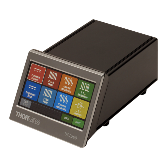
Click a menu topic or tab to get more information. The image above is a screenshot of the main menu panel for the DC2200. Click on a button in the above image to skip to the section of this manual with detailed information on that button's... -
Page 13: Led Settings
LED memory (Thorlabs LEDs only). LED Color shows either the nominal LED wavelength (monochromatic LEDs) or the color temperature (only Thorlabs SOLIS series). If you have connected a custom LED, the above mentioned fields will show "n/a". - Page 14 DC2200 via the LED1 high-power terminal. User Current Limit Thorlabs LEDs come with an internal memory that saves the Max. Current Limit for the given type of LED. This value cannot be exceeded in order to avoid damage to the LED. Beside this limit, a user defined current limit can be set.
-
Page 15: System Settings
Check this box if you want to update the DC2200's firmware Fan Voltage An external fan for heat management can be connected to the DC2200. The fan power can be set between 6.0 V and 13.0 V. Please see the pin assignment to use this feature. -
Page 16: Operation
DC2200 3.3 Operation This section is dedicated to the local operation of the DC2200. Thorlabs offers an application for remote operation as well. 3.3.1 Constant Current Mode In the Constant Current mode, you can set the LED current to a constant value. This panel shows the LED type, the allowed max. -
Page 17: Brightness Mode
LED current, that will be applied when switching on the LED. The 100% brightness is always re- lated to the displayed LED current limit. DC2200 Brightness Mode Panel Set the LED Brightness Tap the LED Brightness line or tap EDIT... -
Page 18: Pwm Mode
DC2200 3.3.3 PWM Mode PWM stands for Pulse Width Modulation. In PWM mode the DC2200 generates rectangular pulses with · adjustable frequency (0.1 Hz to 20 kHz) · adjustable duty cycle (0.1 % to 99.9 %) · adjustable pulse count (1 to 1000; infinite) The pulse amplitude is given by the set value of the LED current, in other words, the LED cur- rent is modulated by a train of rectangular pulses. -
Page 19: Pulse Mode
3.3.4 Pulse Mode The Pulse Mode is comparable to the PWM Mode . Here, the DC2200 generates also rectan- gular pulses with · adjustable ON time (0.001 ms to 10 s) · adjustable OFF time (0.001 ms to 10 s) ·... -
Page 20: Internal Modulation Mode
DC2200 3.3.5 Internal Modulation Mode In this mode the DC2200 generates a signal that modulates the LED current. · waveforms: sine, square and triangle · modulation frequency range: 20 Hz to 100 kHz · adjustable LED current maximum (% LED Cur- rent Minimum to 100 %) ·... -
Page 21: External Modulation Mode
LED Current is the value that is applied to the LED when the TTL input is on H level; it can be adjusted between 0 and the value of LED Current Limit (see upper line in the panel). © 2020 Thorlabs GmbH... -
Page 22: Info
4.0 - 10.0 A 1000 mA 18 kHz 0.5 W Terminal LED1 0.0 - 2.0 A 250 mA 27 kHz 2.0 W 3.3.8 Info Tap the button to display information about the DC2200 hardware and firmware: © 2020 Thorlabs GmbH... -
Page 23: Remote Operation
Remote Application · by your own application When the DC2200 is in remote mode, some additional information appears in the status bar of the display: Blinking when a remote identification request is received. Device switched to Remote state after receipt of 1st remote command. -
Page 24: Installing Software
As an additional advantage to this distribution method, the most recent version of the software will always be available online. The DC2200 software package can be found easily on the website. Download it and unzip the archive, making sure to note the target location. - Page 25 3 Operating Instruction Click 'Next >>' to continue installation. Please do so in the subsequent dialogs. © 2020 Thorlabs GmbH...
- Page 26 DC2200 Click 'I accept...' if you do so, then 'Next >>' to continue. Click 'Next >>' to continue. © 2020 Thorlabs GmbH...
- Page 27 3 Operating Instruction Click 'Finish' to complete installation. You might be prompted to reboot your computer: Click 'Restart'. After the restart, the computer continues the Thorlabs GmbH software installa- tion. If the installer does not continue automatically, please call the setup.exe...
- Page 28 DC2200 Confirm ("Yes") to continue. Click 'Next >>' to continue. Click 'I accept...' if you do so, then 'Next >>' to continue. © 2020 Thorlabs GmbH...
- Page 29 3 Operating Instruction Click 'I accept...' if you do so, then 'Next >>' to continue. Please do so in the subsequent dia- logs. © 2020 Thorlabs GmbH...
- Page 30 DC2200 Confirm ("Yes") to continue. Click 'Restart'. After the restart, the computer continues the Thorlabs GmbH software installa- tion. If the installer does not continue automatically, please call the setup.exe again. Confirm ("Yes") to continue. © 2020 Thorlabs GmbH...
- Page 31 3 Operating Instruction Click "Next >" and then "Install" to continue: © 2020 Thorlabs GmbH...
- Page 32 DC2200 Confirm ("Yes") to continue: Click "Next >". Click "Finish". Now the DC2200 software is installed to your computer. © 2020 Thorlabs GmbH...
-
Page 33: Remote Operation Gui
The GUI (Graphic User Interface) comes up and the software connects automatically to the de- tected DC2200. Note If you forgot to connect the DC2200 first, the GUI waits for the DC2200 to be connected, and then establishes communication automatically. DC2200 GUI. Click a menu topic or tab for more detailed information. - Page 34 DC2200 In order to reconnect the DC2200, click the green Connect button. The "?" icon opens the online help to the Remote Operation software. Status Bar The LED Output button, used to switch the LED on and off, is located on the bottom of the GUI.
- Page 35 3 Operating Instruction Info The Info menu provides information about the DC2200 and the LED connected to the active terminal. Help From the Help menu you can · access the online help of the Remote Operation application, · open the DC2200 product page on Thorlabs' web site, ·...
- Page 36 100% refer to the LED Max. Current Limit or the User Current Limit, whichever is lower. PWM Mode Here, the LED current, the pulse frequency, the duty cycle and the pulse count can be set. For details about the parameters, please see section PWM Mode © 2020 Thorlabs GmbH...
- Page 37 Here, the LED maximum and minimum current, the modulation waveform and frequency can be set. For details about the parameters, please see section Internal Modulation Mode External Mode In External Modulation Mode, only the DC2200 set parameters are displayed, similar to the dis- play shown in External Modulation Mode © 2020 Thorlabs GmbH...
- Page 38 The only parameter that can be adjusted in TTL Mode is the LED current when TTL = H. The LED current can be adjusted between 0 and the LED Max. Current Limit or the User Current Limit, whichever is lower. Please see TTL Modulation Mode for more details. © 2020 Thorlabs GmbH...
-
Page 39: Write Your Own Application
In this section the location of drivers and files, required for programming in different environ- ments, are given for installation under Windows 7 (32 and 64 bit). Note DC2200 software and drivers contains 32 bit and 64 bit applications. In 32 bit systems, only the 32 bit components are installed to C:\Program Files\... -
Page 40: Bit Systems
...\Primary Interop Assemblies\Thorlabs.TLDC2200_32.Interop.dll Example LabWindows CVI C:\Program Files\IVI Foundation\VISA\WinNT\TLDC2200\Examples..\CSample\TLDC2200Sample.prj Basic C Sample to get one measurement Example Visual Studio .Net 2010 C:\Program Files\IVI Foundation\VISA\WinNT\TLDC2200\Examples..\DotNet\Thorlabs DC2200 DotNet Sample.csproj C Sharp sample to get one measurement © 2020 Thorlabs GmbH... -
Page 41: Bit Systems
Header file C:\Program Files (x86)\IVI Foundation\VISA\WinNT\include\TLDC2200.h C:\Program Files (x86)\IVI Foundation\VISA\WinNT\include..\TLDC2200_defines.h C:\Program Files\IVI Foundation\VISA\Win64\Include\TLDC2200.h C:\Program Files\IVI Foundation\VISA\Win64\Include..\TLDC2200_defines.h Static library C:\Program Files (x86)\IVI Foundation\VISA\WinNT\lib\msc..\TLDC2200_32.lib C:\Program Files\IVI Foundation\VISA\Win64\Lib_x64\msc..\TLDC2200_64.lib Function panel C:\Program Files (x86)\IVI Foundation\VISA\WinNT\TLDC2200..\TLDC2200.fp © 2020 Thorlabs GmbH... - Page 42 Example LabWindows CVI C:\Program Files (x86)\IVI Foundation\VISA\WinNT\TLDC2200..\Examples\CSample\TLDC2200Sample.prj Basic C Sample to get one measurement Example Visual Studio .Net 2010 C:\Program Files (x86)\IVI Foundation\VISA\WinNT\TLDC2200..\Example\DotNet\Thorlabs DC2200 DotNet Sample.csproj C Sharp sample to get one measurement © 2020 Thorlabs GmbH...
-
Page 43: Command Reference
1. *IDN? – identification query - read identification code The identification code includes the manufacturer, model code, serial number, and firmware re- vision levels and is sent in the following format: Thorlabs GmbH,MMM,SSS,X.X.X, where is the model code is the serial number X.X.X... - Page 44 6. *WAI – wait-to-continue – wait until previous commands are completed The *WAI command is a no operation command for the instrument and thus, does not need to be used. It is there for conformance to IEEE488.2. © 2020 Thorlabs GmbH...
-
Page 45: Scpi Command Reference
Query the spectrum information of the LED head. :SPECtrum? Positive values describe the nominal LED center wavelength in nm. Negative values describe the color temperature in K. The value 0.0 describes "in- formation not available" © 2020 Thorlabs GmbH... - Page 46 Returns the positive transition filter :NTRansition <value> Sets the negative transition filter :NTRansition? Returns the negative transition filter :ENABle <value> Sets the enable register Returns the enable register :ENABle? :PRESet Return status registers to default states. Vol.2 §20.2 © 2020 Thorlabs GmbH...
- Page 47 MAX return the measurement value range pos- sible. SENSe5 LED temperature sensing subsystem commands Command Description SCPI SENSe5 Path to LED temperature sensing [:TEMPerature]? [{MIN|MAX}] Returns the measured LED temperature. Parameters MIN and MAX return the measurement value range possible. © 2020 Thorlabs GmbH...
- Page 48 These settings only have an effect while in Pulse mode [:BRIGhtness][:LEVel] [:AMPLitude] {MIN|MAX|<perc>} Sets LED brightness set value in percent of currently set limit current [:AMPLitude]? [{MIN|MAX}] Query LED brightness set value in percent of currently set limit current © 2020 Thorlabs GmbH...
- Page 49 Returns the temperature unit Vol.2 §25.3 CALibration subsystem commands Command Description SCPI CALibration :STRing? Returns the console’s calibration string that was written to the console at the latest calib- ration procedure (usually the calibration date). Example: “15-Jul-2015” © 2020 Thorlabs GmbH...
- Page 50 Get last LED head temperature measure- ment READ? Starts new measurement (as configured) Vol.2 §3.3 and read data MEASure[:SCALar] Vol.2 §3.4 :CURRent[1][:DC]? Perform LED current measurement :VOLTage[1][:DC]? Perform LED voltage measurement Perform LED head temperature measure- :TEMPerature[1]? ment © 2020 Thorlabs GmbH...
-
Page 51: Status Reporting
4 Write Your Own Application 4.3.3 Status Reporting The figure below gives an overview of the device’s status reporting structure. See also section STATus subsystem commands for a detailed description of the related commands and their syntax. © 2020 Thorlabs GmbH... - Page 52 The Questionable Data Status Structure is described in SCPI1999.0 Vol1 §9.4. Bit # Mnemonic Description 15..13 See SCPI1999.0-Vol1-§9.4 – flags are not implemented reserved, read as 0 12..3 LED temperature measure LEDT LEDV LED voltage measure LED current measure LEDC © 2020 Thorlabs GmbH...
- Page 53 The Auxiliary Status Register Status Byte Register reports auxiliary device states. Bit # Description 15..13 reserved, read as 0 Screen touched reserved, read as 0 Console fan failure Power supply failure 8..0 reserved, read as 0 © 2020 Thorlabs GmbH...
-
Page 54: Error Reporting
PRM module overheated Output current limit reached Sensor failed Supply 3.3V digital failed Supply 1.2V digital failed Supply 12V analog failed Supply -12V analog failed Supply 5V analog failed Supply 12V VTM module and internal fan failed © 2020 Thorlabs GmbH... - Page 55 I²C#1 bus arbitration lost I²C#2 wires stuck I²C#2 bus error I²C#2 slave address not acknowledged I²C#2 incomplete write operation I²C#2 bus arbitration lost Nonvolatile memory timed out Nonvolatile memory checksum error Nonvolatile memory address overflow Nonvolatile memory not supported © 2020 Thorlabs GmbH...
- Page 56 Operation is not applicable Numeric value error Value minimum reached Value maximum reached Step size lower limit reached Step size upper limit reached Selection limit reached Value is out of range Not editable while output is ON © 2020 Thorlabs GmbH...
- Page 57 1-wire file system: can't open file 1-wire file system: can't read file 1-wire file system: can't close file Invalid 1-wire device handle Invalid 1-wire device address Invalid 1-Wire bridge channel Invalid 1-Wire bridge index -100 General command error © 2020 Thorlabs GmbH...
- Page 58 -213 Init ignored -220 Parameter error -221 Settings conflict -222 Data out of range -223 Too much data -224 Illegal parameter value -230 Data corrupt or stale -240 Hardware error -310 System error -311 Memory error © 2020 Thorlabs GmbH...
- Page 59 Calibration memory lost -313 -314 Save/recall memory lost Configuration memory lost -315 -321 Out of memory Self-test failed -330 -340 Calibration failed Queue overflow -350 -363 Input buffer overrun Time out error -365 Query INTERRUPTED -410 © 2020 Thorlabs GmbH...
-
Page 60: Maintenance And Service
DC2200 5 Maintenance and Service Protect the DC2200 from adverse weather conditions. The DC2200 is not water resistant. Attention To avoid damage to the instrument, do not expose it to spray, liquids or solvents! The unit does not need a regular maintenance by the user. It does not contain any modules and/or components that could be repaired by the users themselves. -
Page 61: Firmware Update
In order to update the DC2200 firmware, a newer firmware image (file extension *.dfu) and the Thorlabs DFU Wizard are required. The DFU Wizard is a software tool to upload a firmware image to the DC2200. You will find it installed to your computer after downloading and installing the DC2200 Software package from site. - Page 62 DC2200 4. Click Next > to continue. 5. Click Browse to select the downloaded *.dfu file, then Select: © 2020 Thorlabs GmbH...
- Page 63 5 Maintenance and Service 6. Click Next > to continue. 7. If you wish to save a backup of your current firmware, please check the appropriate box in above screen. © 2020 Thorlabs GmbH...
- Page 64 DC2200 8. Click Start. The DFU Wizard searches for DFU capable devices, ... 9..switches the DC2200 to DFU upload mode 10. and begins the upload: © 2020 Thorlabs GmbH...
- Page 65 5 Maintenance and Service 11. Do NOT interrupt the process, this may cause your DC2200 to become inoperable! 12. Click Finish. The DFU application closes, and the DC2200 reboots with the new firmware. 13. Disconnect the USB cable. © 2020 Thorlabs GmbH...
-
Page 66: Error Messages
DC2200 5.3 Error Messages Error messages are displayed in the status bar of the DC2200 display. There are indicators that might light up, or text messages may come up. Indicators Possible reasons: · The forward voltage of the LED exceeded the internal limit (e.g. by disconnecting the LED) ·... - Page 67 5 Maintenance and Service Possible reasons: · The DC2200 heated up internally beyond 85° C. Troubleshooting: · The DC2200 switches off in this case automatically. · Prior to switching it on again, please make sure that the fan works properly and that vent- ilation slots are not covered.
-
Page 68: Appendix
Pulse Mode On Time 0.001 ms - 10 s Off Time 0.001 ms - 10 s Counts 1 to 1000; infinite Internal Modulation Mode Waveforms Sine, Square, Triangle Modulation Frequency Range 20 Hz - 100 kHz © 2020 Thorlabs GmbH... - Page 69 ) Given for an output current at "High" TTL level not exceeding 10% of the selected current range limit. Warm-up time for rated accuracy: < 10 min. All technical data are valid at 23 ± 5°C and 45 ± 15% rel. humidity (non condensing) © 2020 Thorlabs GmbH...
-
Page 70: Dimensions
DC2200 6.2 Dimensions © 2020 Thorlabs GmbH... -
Page 71: Interlock Circuit
(total resistance < 1 kW). 6.4 Connect a Custom LED You can connect a custom LED to your DC2200 using the supplied connection cables. Custom High Power LED (up to 10 A - Terminal LED1) - Page 72 Use the supplied cable CAB-LEDD1: Connection scheme: Color Description brown LED anode white LED cathode black DO NOT CONNECT blue DO NOT CONNECT Attention! Do NOT connect anything to the black and blue wires! The DC2200 might be damaged! © 2020 Thorlabs GmbH...
-
Page 73: Return Of Devices
6.6 Manufacturer Address Manufacturer Address Europe EU-Importer Address Thorlabs GmbH Thorlabs GmbH Münchner Weg 1 Münchner Weg 1 D-85232 Bergkirchen D-85232 Bergkirchen Germany Germany Tel: +49-8131-5956-0 Tel: +49-8131-5956-0 Fax: +49-8131-5956-99 Fax: +49-8131-5956-99 www.thorlabs.de www.thorlabs.de Email: europe@thorlabs.com Email: europe@thorlabs.com © 2020 Thorlabs GmbH... -
Page 74: Certifications And Compliances
DC2200 6.7 Certifications and Compliances © 2020 Thorlabs GmbH... -
Page 75: Warranty
For warranty repairs or service the unit must be sent back to Thorlabs GmbH. The customer will carry the shipping costs to Thorlabs GmbH, in case of warranty repairs Thorlabs GmbH will carry the shipping costs back to the customer. -
Page 76: List Of Acronyms
DC2200 6.10 List of Acronyms Device Firmware Update Graphic User Interface Light Emitting Diode Pulse Width Modulation Transistor- Transistor Logic Universal Serial Bus © 2020 Thorlabs GmbH... -
Page 77: Thorlabs Worldwide Contacts And Weee Policy
Contact Thorlabs for more information. Waste treat- ment is your own responsibility. “End of life” units must be returned to Thorlabs or handed to a company specializing in waste recovery. Do not dispose of the unit in a litter bin or at a public waste disposal site. - Page 78 www.thorlabs.com...
Need help?
Do you have a question about the DC2200 and is the answer not in the manual?
Questions and answers