Table of Contents
Advertisement
Advertisement
Table of Contents

Summary of Contents for NSK iClave Plus
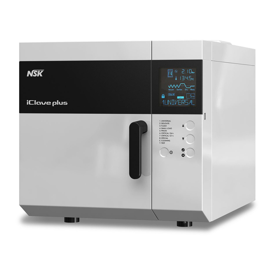
- Page 1 plus Water Steam Sterilizer – Class B OPERATION MANUAL Rev. 1 Date: June 2015...
- Page 2 NSK. Information in this manual is subject to change without any warning or prior notice by NSK and does not represent a commitment for the vendor.
-
Page 3: Table Of Contents
TABLE OF CONTENTS GENERAL ............................2 1.1 INTRODUCTION ..........................2 1.2 CONFORMITY TO EUROPEAN DIRECTIVES ..................2 1.3 PACKAGE DIMENSIONS AND WEIGHT ..................... 3 1.4 UNPACKAGING ........................... 3 FAMILIARIZATION ........................4 2.1 OVERALL DIMENSIONS ........................4 2.2 USABLE SPACE IN THE CHAMBER ....................4 2.3 SAFETY FEATURES .......................... -
Page 4: General
Please, check for the packing integrity and no evident damages or missing parts (see delivery note). IN CASE OF DAMAGES OR MISSING PARTS, PLEASE IMMEDIATELY INFORM AND IN DETAIL THE FORWARDER, NSK AND ITS AREA AGENT. CONFORMITY TO EUROPEAN DIRECTIVES The sterilizer... -
Page 5: Package Dimensions And Weight
PACKAGE DIMENSIONS AND WEIGHT Total weight: 58 Kg Store the package for possible future shipment. UNPACKAGING... -
Page 6: Familiarization
2. FAMILIARIZATION OVERALL DIMENSIONS Net weight: 47 Kg Full load weight: 58 Kg USABLE SPACE IN THE CHAMBER Diameter: 240 mm Depth: 384 mm Capacity: 17,5 l Useful dimensions per tray: 315 x 214 mm (x 2), 315 x 168 mm (x 2) Useful tray volume: 10 l... -
Page 7: Safety Features
SAFETY FEATURES The sterilizer features several devices that assure the full safety for the operators. Door with dual lock control An electromechanical device allows the door to be opened only if the following conditions are met: unit power supplied and turned on no current alarms internal pressure not dangerous for the operator For further safety, to unblock the door at the end of cycle or in case of alarm it is necessary to press the... -
Page 8: Precautions
PRECAUTIONS The international norms concerning safety and sterilization process defines the following figures: OPERATOR: the person operating the unit to achieve the expected result. RESPONSIBLE AUTHORITY: person or group responsible for the use and maintenance of the unit, he or she also has to make sure that: all personnel who operate or maintain the equipment are trained in its operation and in its safe use. -
Page 9: Front And Rear View
FRONT AND REAR VIEW Safety valve connection Main (fresh) water tank feeding point Bacterial filter Temperature sensor Door gasket Control panel Door USB port Door handle Air line filter Quick connector for waste water tank drain Chamber water inlet Water outflow filter Quick connector for fresh water tank drain Water inlet filter Automatic draining of... -
Page 10: Standard Accessories
STANDARD ACCESSORIES Drain tube (P/N 119001) Filter spanner (P/N 105228) Cleaning tabs Tray holder Water filter (PN/ 105619) (P/N 105320) Tray rack (P/N 105078) (+ 2 pcs extra) Bacterial filter Warranty paper (P/N 021008) (+ 1 pcs extra) Operating Manual 2+2 Trays (P/N 105076 - 105077) ... -
Page 11: Installation
3. INSTALLATION BASIC REQUIREMENTS Check that the mains voltage of your electrical installation matches the value indicated on the equipment plate, the electrical socket is capable to supply at least 14A and is provided with an efficient earth connection. In case the in- stallation makes inaccessible the power supply switch, pro- vide for a proper electrical breaker. -
Page 12: Getting Started
GETTING STARTED These operations should be carried out only by qualified personnel, wrong settings could affect the quality of the sterilization. Check the electrical requirements and connect the power supply cable to the mains socket. 1. The equipment is delivered with empty tank and is therefore necessary to add demineralized water. -
Page 13: Notes About Altitude Compensation
NOTES ABOUT ALTITUDE COMPENSATION For a proper operation of the pressure control devices, an altitude compensation feature has been intro- duced. During the installation procedure it is necessary to set the altitude value (referred to sea level) for the site where the unit operates. -
Page 14: Operating Instructions
4. OPERATING INSTRUCTIONS FRONT PANEL COMMAND/SIGNALING The front panel is equipped with control keys, signalling Led’s and displays. A slight push on a key will activate the command. Phase in progress signalling Led turned on or flashing during the phases of the cycle. LCD displays Visualize (from the top) the value of the parameters Time (when the unit is OFF), Temperature (measure unit: °C) - Page 15 Door locked. hen turned off, you can open the door. Double wrapping, it lights up when you select the cycles 1, 2, 5, 6 or 7. Packs, it lights up when you select the cycles 2 or 7. Single wrapping, it lights up when you select the cycle 4. Unwrapped instruments, it lights up when you select the cycle 3.
-
Page 16: Usb Memory Connection
Because the file is not produced by a computer, in the file information is missing the creation date, this fea- ture indicates that the file is really release by the unit and not manually created by PC NSK is not responsible for data lost for missing care on the database or defective data support... -
Page 17: Running A Sterilizazion Cycle
RUNNING A STERILIZAZION CYCLE 1. Turn on the equipment by means of the switch located on the rear panel. The display shows date, time and OFF; pushing UP, DOWN or START for short time) the brightness of the display increases for few seconds Power 2. -
Page 18: Starting A Sterilization Cycle
4.3.2 Starting a sterilization cycle Press the key START/STOP to start the selected cycle. The programs 3 and 8 do not warrant the Class B sterilization; to start these types of cycle, hold down START the key longer than 3 seconds ... -
Page 19: Stopping The Cycle
Start/Stop To unlock the door before opening it, press the key The cycle is over and the load can be taken out . ATTENTION: instrument and chambers are hot If a label printer is used, at the end of the cycle the display will ask to select the number of labels need- ed, select the value with UP and DOWN, than opening the door the printer will release the labels. -
Page 20: Topping Up And Draining The Waste Water Tank
TOPPING UP AND DRAINING THE WASTE WATER TANK The sterilizer is fitted with two 4-liters tanks; main tank for the fresh demineralized water and recovery tank for the waste water . The hydraulic system does not reuse the condensate obtained during the sterilization process; this conden- sate is collected in the waste water tank which must be periodically drained (except when used in combina- tion with the water supply system Purity). -
Page 21: Programming
5. PROGRAMMING SETUP MENU Push together the buttons UP and DOWN to enter in the setup pages, use DOWN (or UP to start from the last option) to select the function, START to set, POWER to go back. The following function may be adjusted: ... - Page 22 “ECO” turns off the heating when not strictly needed Push START to set and go back to “ENERGY”, with DOWN (or UP) select another menu. “EXP DAYS” sets the count for the expiration date printed on the adhesive labels (option). Push START to enter, using UP and DOWN select the number of days.
-
Page 23: Maintenance
6. MAINTENANCE AUTOMATIC PERIODIC CLEANING CYCLE For a proper operation of your sterilizer it is indispensable that a correct and regular maintenance is carried out. To this end, it is important to perform a cleaning procedure, as described on the following, at least once every 15 days or, in case of intense usage, every two water full of the main tank. -
Page 24: Cleaning/Replacing The Water Inlet Filter
The frequency of these checks is regulated at local country level; check the regulations in force. The norm references for the tests is EN13060 ch. 10.6 for the B type cycles and ch. 10.5 for the S type For any explanations or information, contact your authorized reseller or directly NSK. 6.4.1 Porous load test (B&D) -
Page 25: Troubleshooting
7. TROUBLESHOOTING INITIAL AUTO-TEST Each time the equipment is switched on, starts an automatic test (duration approx. 15 s) checking sequen- tially any main component. Three beeps signal the end of the auto-test and, if positively passed, the message Card Good is displayed . Whatever fault detected, it will be shown on the display and stored with the alarm code of the Table C (see chapter ALARM). -
Page 26: Alarms
8. ALARMS GENERAL With equipment switched on and during every cycle, the supervisory system of the equipment constantly monitors the characteristic parameters of the different sterilization phases, the proper operation and the sta- tus of the devices. Any detected anomaly or fault is promptly signalled through specified messages, coded alarms and acoustic signalling. -
Page 27: Pre-Warning Alarms
PRE-WARNING ALARMS The alarms shown on table B do not stop the operation of the sterilizer, but warn that a problem might inter- fere with the correct working of the sterilizer. Check the trouble and promptly carry out the recommended action. In case of fault, the message Need Test will appear along with the code number of the detected alarm. -
Page 28: Class B Additional Alarms
Alarm code Cause Solution AL 12 Temperature out the normal range Perform the automatic cleaning cycle (§ 6.1). Steam temperature sensor faulty Call for a technical service AL 13 Chamber temperature sensor faulty Call for a technical service AL 15 AL 16 Pressure sensor faulty Call for a technical service... -
Page 29: Connections
To set the language for the report printout, see chapter 5. The PRINTER port interfaces directly a printer only, and through a dedicated interface can be con- nected to a PC to store the cycle files. Contact the reseller or directly NSK for more info. Example of alarmed report... -
Page 30: Connection To A Computer
CONNECTION TO A COMPUTER (ONLY FOR SERVICE AND FUTURE APPLICATIONS) The serial port can be also used for the connection to an external PC. This function is only available for Ser- vice technician, and allows to perform more accurate tests as well as a new approach to the service and cer- tification aspect. -
Page 31: Appendix Service Book
“ NEED SERVICE”. This feature is in compliance with the norm EN13060 and answers to spe- cific safety requirements. The maintenance activities must be performed by authorized technicians ( provided with card or certificate released by NSK ) and reported on this Service Book. Model .............. - Page 32 APPENDIX SERVICE BOOK □ □ □ □ Sterilizer OK Sterilizer OK Date ................Date ................No. of cycle ....Cleaning cycles ......No. of cycle ....Cleaning cycles ......Aborted cycles ..Alarm code ........Aborted cycles ..Alarm code ........Technician name: .............
- Page 33 APPENDIX SERVICE BOOK □ □ □ □ Sterilizer OK Sterilizer OK Date ................Date ................No. of cycle ....Cleaning cycles ......No. of cycle ....Cleaning cycles ......Aborted cycles ..Alarm code ........Aborted cycles... Alarm code ........Technician name: ............
- Page 34 APPENDIX SERVICE BOOK □ □ □ □ Sterilizer OK Sterilizer OK Date ................Date ................No. of cycle ....Cleaning cycles ......No. of cycle ....Cleaning cycles ......Aborted cycles ..Alarm code ........Aborted cycles ..Alarm code ........Technician name: .............
- Page 36 Änderungen im Zuge We reserve the right Ci riserviamo il diritto Sous réserve de Reservados los technischer Weiterent- to make any altera- di apportare modifiche modifications dues derechos de wicklung vorbehalten. tions which may be a seguito di migliorie au progrès tech- modificatiòn en virtud due to technical im- tecniche.
Need help?
Do you have a question about the iClave Plus and is the answer not in the manual?
Questions and answers