Clarke Metalworker CMD300 Operation & Maintenance Instructions Manual
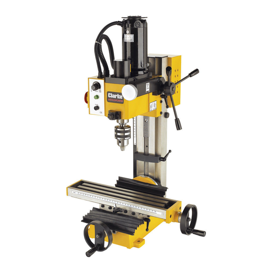
Mill drill
Hide thumbs
Also See for Metalworker CMD300:

Related Manuals for Clarke Metalworker CMD300


Summary of Contents for Clarke Metalworker CMD300
- Page 1 MILL DRILL MODEL NO: CMD300 PART NO: 7610860 OPERATION & MAINTENANCE INSTRUCTIONS ORIGINAL INSTRUCTIONS GC1120 - rev 6...
-
Page 2: Environmental Protection
INTRODUCTION Thank you for purchasing this CLARKE product. Before attempting to use this product, please read this manual thoroughly and follow the instructions carefully. In doing so you will ensure the safety of yourself and that of others around you, and you can look forward to your purchase giving you long and satisfactory service. -
Page 3: Specification
SPECIFICATION Motor Supply 230Vac/ 50Hz / 1ph Motor 470 W Fuse link rating 5 Amp Product Weight 51 kg Operating temperature - 40 Sound Pressure Level 82 dB LpA Max drill Capacity 13 mm End mill capacity 16mm Face mill capacity 30mm Mill/Drill head angle -45 to +45... -
Page 4: General Safety Rules
2. Always keep guards in place and in working order. A guard or other part that is damaged should be properly repaired or replaced by your Clarke service department, unless otherwise indicated in this instruction manual. - Page 5 Check for alignment of moving parts, binding of moving parts, breakage of parts, mounting or other condition that may affect its operation. 7. Have defective switches repaired by your Clarke service department. Do not use a power tool if the switch does not turn it on and off.
- Page 6 3. Always make all adjustments with the power off. 4. Always use the correct speeds for the bit size and the type of material being worked. 5. Never leave the machine unattended whilst it is running. Turn the machine OFF and do not leave until it has come to a complete stop. 6.
-
Page 7: Electrical Connections
ELECTRICAL CONNECTIONS WARNING! READ THESE ELECTRICAL SAFETY INSTRUCTIONS THOROUGHLY BEFORE CONNECTING THE PRODUCT TO THE MAINS SUPPLY. Before switching the product on, make sure that the voltage of your electricity supply is the same as that indicated on the rating plate. This product is designed to operate on 230VAC 50Hz. - Page 8 PARTS INVENTORY (LOOSE ITEMS) 1. Double-ended open spanner 8/10mm AF 2. Double-ended open spanner 14/17mm AF 3. Double-ended open spanner 17/19mm AF 4. 2 x T-nuts 5. Set hex wrenches, 3, 4, 5 & 6mm 6. Drill chuck with tapered shank 7.
- Page 9 UNPACKING Thank you for purchasing this CLARKE Milling/Drilling Machine, designed for drilling, deep milling and face milling of small workpieces with maximum dimensions of 300mm x 200mm x 200mm. IMPORTANT: Careful consideration is required when choosing the location for the machine with regard to table movement, Mill/Drill head movement and location of the power supply.
- Page 10 PARTS IDENTIFICATION Parts & Service: 020 8988 7400 / E-mail: Parts@clarkeinternational.com or Service@clarkeinternational.com...
-
Page 11: Operation
7. Screw a handle to each of the table cross feed and longitudinal feed handle and secure with the locknuts provided. 8. If using the Drill chuck, attach the clear plastic chuck guard to its mount, using the single screw provided. 9. - Page 12 4. Switch OFF by turning the rotary switch fully anticlockwise, then move the Hi-Lo range lever to the ‘H’ - high position, and repeat the process. NOTE: In case of emergency, hit the switch cover quickly. The cover will latch down and the motor will be switched OFF.
- Page 13 3. In order to hold the spindle, insert the tommy bar into the hole in the side of the head so that it locates in the hole in the spindle, see Fig. 5. Hold the spindle still whilst nipping up the draw bolt.
- Page 14 Alternatively, clamps may be used. A suitable vice and a ‘T’ nut and clamp set designed specifically for this machine, are available from your Clarke dealer. Please refer to Accessories on page 25.
- Page 15 12/13. Please note that a range of accessories, including collet sets and collet chuck sets which are used to secure the cutter, are available from your Clarke dealer - see Accessories on pages 25-27.
- Page 16 GENERAL NOTES ON MILLING Set up the workpiece in a similar manner to that for drilling. • Slowly bring the cutter into contact with the work piece and start machining. • DO NOT attempt to make too bigger cuts than the cutter and machine are capable of, it is much better and safer to make several small passes.
-
Page 17: Maintenance
A good rule of thumb is, the smaller the hole or depth of cut, and the softer the material to be machined etc, the faster the speed. Please note that It is not within the scope of this manual to provide a tutorial on cutting speeds or the methods used to determine spindle speeds (RPM), for your particular application. - Page 18 without unnecessary slackness. The longitudinal slide for example carries four adjusters, shown in Fig.10. To adjust, first ensure that the slides are lubricated with a thin film of machine oil as described previously. Slacken off all adjuster locknuts using the hex wrench provided, and back off each adjuster by half a turn.
-
Page 19: Component Parts
COMPONENT PARTS Parts & Service: 020 8988 7400 / E-mail: Parts@clarkeinternational.com or Service@clarkeinternational.com... - Page 20 COMPONENT PARTS Parts & Service: 020 8988 7400 / E-mail: Parts@clarkeinternational.com or Service@clarkeinternational.com...
- Page 21 COMPONENT PARTS Parts & Service: 020 8988 7400 / E-mail: Parts@clarkeinternational.com or Service@clarkeinternational.com...
- Page 22 COMPONENT PARTS No Description Description Base Screw M6x8 X-axis feed screw Y-axis jib strip Key 4 x 16 Saddle Dial Y-axis jib strip Hand wheel Y-axis screw nut Nut M8 Cap screw M6x25 Knob Vertical post seat Screw M8x55 39-1 Shaft Cap screw M6 x8 39-2 Key 8x12 Plate(1)
- Page 23 Cap screw M6x25 Upper end screw M6 Spindle box seat Setscrew M6x6 Jib strip Spring Limit block Ball Jib strip Handle seat Scale Double head bolt M8 Vertical post Knob Electric box Warning label Locknut M24 Controller Large washer Label Connecting strut Shaft Key 5x5x40...
-
Page 24: Declaration Of Conformity
139 Ball bearing 80101 Key 4x6 140 Drive gear Spring support 141 Bar Torsion spring 142 Link board Cover 143 Set screw M5x8 144 Self tapping screw Extension tube 145 Hi/low label Supporting arm 146 Motor cover Screw 147 Motor connecting flange Washer 148 Screw M6x10 Internal circlip 12... - Page 25 ACCESSORIES MILL CHUCK SET Part Number: 7610866 A set comprising 7 collets, a chuck and ‘C’ spanner. Collet sizes: • 4 mm • 6 mm • 8 mm • 10 mm • 12 mm • 14 mm • 16 mm 1.
- Page 26 Collet Set (MT3) Part Number: 7610864 Set of 7 Collets for use with HSS End Mills: Insert the appropriate collet into the spindle. Insert the draw bolt provided, into the spindle from the top and screw onto the collet a few turns. Insert the appropriate mill into the jaws of the collet and tighten the draw bolt.
- Page 27 INDEXABLE CARBIDE END MILL Part Number: 7910870 Simply insert the shank of the mill into the spindle and screw on to the draw bolt. Tighten using the tommy bar in the hole in the side of the head, into the spindle, and spanner on the draw bolt head.
Need help?
Do you have a question about the Metalworker CMD300 and is the answer not in the manual?
Questions and answers