Table of Contents
Advertisement
EMH metering
GmbH & Co. KG
Neu-Galliner Weg 1 • 19258 Gallin
GERMANY
Tel.
+49 38851 326-0
Fax
+49 38851 326-1129
E-Mail info@emh-metering.com
Web
www.emh-metering.com
Tel.
+49 38851 326-1930 (Technical Support)
E-Mail support@emh-metering.com
LZQJ-XC
Digital 4-Quadrant/Combi meter
EN
Instructions for use
Scope of delivery ............................................................................................... 2
Important notes.................................................................................................. 2
Target group .................................................................................................. 2
Intended use.................................................................................................. 2
Maintenance and warranty information ......................................................... 2
Care and disposal instructions ...................................................................... 3
Basic safety instructions ................................................................................ 4
Notes on correctness of measurements........................................................ 4
Technical data.................................................................................................... 4
Housing, display and operating elements.......................................................... 6
Nameplate ..................................................................................................... 7
LC-displays .................................................................................................... 8
a) VDEW-display ....................................................................................... 8
b) 4-line display ........................................................................................... 10
Installation and commissioning........................................................................ 12
a) Transformer connected meter ................................................................. 14
b) Meter for direct connection up to 60 A..................................................... 16
c) Meter for direct connection up to 100 A ................................................... 17
Terminal cover ............................................................................................. 19
Readout battery (optional) ........................................................................... 19
Installation check register C.86.0 .................................................................... 20
Error register F.F .............................................................................................. 22
Meaning of the error flags: .......................................................................... 22
Communication module ................................................................................... 23
Abbreviations ................................................................................................... 24
EU Declaration of Conformity for the LZQJ-XC ............................................... 26
Version: November 2020; Product specifications are subject to change without notice!
LZQJXC-BIA-E-2.51
Advertisement
Table of Contents

Related Manuals for EMH metering LZQJ-XC Series


Summary of Contents for EMH metering LZQJ-XC Series
-
Page 1: Table Of Contents
EMH metering GmbH & Co. KG Neu-Galliner Weg 1 • 19258 Gallin GERMANY Tel. +49 38851 326-0 +49 38851 326-1129 E-Mail info@emh-metering.com www.emh-metering.com Tel. +49 38851 326-1930 (Technical Support) E-Mail support@emh-metering.com LZQJ-XC Digital 4-Quadrant/Combi meter Instructions for use Scope of delivery ....................2 Important notes.................... -
Page 2: Scope Of Delivery
Scope of delivery Please check the content of the package, before starting with the instal- lation and commissioning. y 1 LZQJ-XC device y 1 Installation and commissioning instruction If the content is incomplete or damaged, please contact your source of supply. -
Page 3: Care And Disposal Instructions
Care and disposal instructions DANGER! Contact with live parts is dangerous to life! Before the housing of the meter is cleaned, all conductors that the meter is connected to must be de-energised. Clean the housing using a dry cloth. Do not use chemical cleaning agents! The following table lists the components and how to handle them at the end of their life cycle:... -
Page 4: Basic Safety Instructions
Basic safety instructions Please adhere to the following basic safety instructions: y Read all the enclosed instructions and information. y Adhere to the warnings on the device and in the documents. y Always work on the device in a safety-conscious and threat-aware manner. - Page 5 Excess voltage OVC III (as per EN 62052-31) category Rated impulse 4kV (as per EN 62052-31) voltage Measuring voltage inputs 3x500V, 3x400/690V, 3x690V: UImp = 8kV Input S0-input max. 27 V DC, 27 mA, not potential-free Low voltage 18...40 V DC System voltage 58...240 V Output...
-
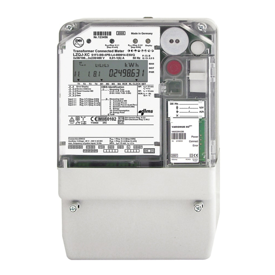
Page 6: Housing, Display And Operating Elements
Housing, display and operating elements 1 - Nameplate 2 - Test-LED for reactive power (continuously lit up = no energy con- sumption or incorrect current direction, non-reverse ratchet active) 3 - LC-display 4 - Test-LED for active power (continuously lit up = no energy con- sumption or incorrect current direction, non-reverse ratchet active) 5 - Optical call-up sensor 6 - Meter cover... -
Page 7: Nameplate
Nameplate 1 - Serial number 2 - Year of construction 3 - Test-LED for reactive power (only LZQJ-XC) 4 - Optical call-up sensor 5 - Test-LED for active power 6 - Registered quadrants 7 - Accuracy class 8 - OBIS-index of the most important registers 9 - Product standard 10 - Utilisation category 11 - Excess voltage category... -
Page 8: Lc-Displays
LC-displays a) VDEW-display 1. The operation indicator shows the energy direction currently measured by the meter (supply/drawing of active power, inductive/ capacitive reactive power). If there is a consumer current flowing, the energy direction arrows show in which quadrant the value is measured. - Page 9 6. In the additional cursor field the operational status of the meter is indicated. The arrows show if a manipulation or an installation error has been registered or if the power threshold has been exceeded. The cursor is active, if a manipulation at the terminal cover, the housing cover or by magnetic influences has been registered.
-
Page 10: B) 4-Line Display
b) 4-line display 1. In the comment text the displayed values are described in clear text. 2. The energy direction indicator shows the direction of the measured energy (+ for drawing, - for supply). 3. In the value area the measured values are indicated. 4. - Page 11 9. The symbol for the data read-out appears when data is sent to the meter or when the meter sends data to the PC. 10. The symbol for the clock control shows if the tariff control of the meter is controlled by the internal clock. 11.
-
Page 12: Installation And Commissioning
Installation and commissioning Meter of the LZQJ-XC series are suitable for wall mounting according to DIN 43857-2. When connecting the meter, observe the appropriate wiring diagram, which you can find inside the terminal cover and as a part of the delivery docu- ments. - Page 13 DANGER! Contact with live parts is dangerous to life! S0-inputs are not potential-free. The S0-inputs are, depending on the voltage version, internally electrical connected to the measurement connections or to the auxiliary voltage and therefore potential carrying. y Observe the device-specific wiring diagram inside the terminal cover.
-
Page 14: A) Transformer Connected Meter
W x H or d (mm) Minimum connection cross section (mm²) Maximum connection cross section (mm²)* Maximum torques for terminals (Nm) EMH metering GmbH & Co. KG Neu-Galliner Weg 1 • 19258 Gallin GERMANY Tel. +49 38851 326-0 +49 38851 326-1129 E-Mail info@emh-metering.com... - Page 15 Button for manipulation Optical fibre recognition connection DANGER! Danger to life due to excess voltages on the terminals of the current paths! The voltages on the terminals of the current paths must not be higher than the rated voltages of the voltage circuits and not be higher than 300 V towards N.
-
Page 16: B) Meter For Direct Connection Up To 60 A
b) Meter for direct connection up to 60 A DANGER! Inproper installation endangers life and health and carries the risk of malfunction and property damages! y Use a selective overcurrent protection for 63 A according to the applicable TAB (e.g. a main circuit breaker) before the meter. y Secure the connecting paths in accordance with the applicable technical regulations and in accordance with the power specification on the name plate of the meter. -
Page 17: C) Meter For Direct Connection Up To 100 A
Button for manipulation Optical fibre recognition connection For testing the device, the voltage paths are interrupted by a path separator. Remove the path separator for normal operation! c) Meter for direct connection up to 100 A DANGER! Inproper installation endangers life and health and carries the risk of malfunction and property damages! y Use a selective overcurrent protection for 100 A gemäß... - Page 18 Current N-tap Additional Meter up to 100 A terminals terminal terminals 1, 3, 4, 6, 7, 9 10, 12 Terminal dimension 9,8 x 11,2 10,0 2,6 x 2,2 W x H or d (mm) Minimum connection 16,0 16,0 cross section (mm²) Maximum connection 35,0 35,0...
-
Page 19: Terminal Cover
Terminal cover To prevent unauthorized access to the terminals, the terminal cover is mounted with sealing screws, which you can secure with seals. NOTICE! Property damage due to excessive torque! y Tighten the sealing screws with a torque of 0,5 Nm. Readout battery (optional) The exchangable readout battery enables the reading of the display and the readout of the meter via the optical data interface D0 when the... -
Page 20: Installation Check Register C.86.0
Installation check register C.86.0 The installation check register C.86.0 registrates installation errors. Normally, it is shown in the scrolling list or can be called up via the call- up list. C.86.0 (0 0 0 0 0 0 0 0) Manipulation recognition Wrong phase sequence Phase failure Negative energy direction... - Page 21 Event Value Meaning Manipulation recognition Manipulation of the meter cover Manipulation of the terminal cover Manipulation by magnetic fields Manipulation input Wrong phase sequence Loss of neutral Wrong phase sequence Assymetric current, z. B. 30 % Assymetric current, z. B. 18 % Phase failure Phase failure L1 Phase failure L2...
-
Page 22: Error Register F.f
Error register F.F The meter has an error register with 32 error flags (eight-digit hexadeci- mal value), which registers the functional errors of the meter. The output of the error tab is performed via the display and one of the read-out lists. -
Page 23: Communication Module
F.F(00000600) Error in set-checksum + Error in code-checksum F.F(00000700) Error in par-checksum + Error in set-checksum + Error in code-checksum F.F(00000800) Error in system-checksum F.F(00000900) Error in par-checksum + Error in system-checksum F.F(00000A00) Error in set-checksum + Error in system-checksum F.F(00000B00) Error in par-checksum + Error in set-checksum +... -
Page 24: Abbreviations
Abbreviations Accuracy class optical Interface acc. to EN 62056-21 Deutsches Institut für Normung e.V. (German Institute for Standard) European standards Utility Current International Electrotechnical Commission Ingress Protection Infrared L1, L2, L3 External conductor Liquid Crystal Liquid Crystal Display Light Emitting Diode Neutral conductor OBIS Object-Identifikation-System... -
Page 26: Eu Declaration Of Conformity For The Lzqj-Xc
EU Declaration of Conformity for the LZQJ-XC You will find the current EU Declaration of Conformity on the internet site www.emh-metering.com in the “Products” area in the product description of the meter.
Need help?
Do you have a question about the LZQJ-XC Series and is the answer not in the manual?
Questions and answers