
Related Manuals for ELECRAFT T1


Summary of Contents for ELECRAFT T1
- Page 1 L E C R A F T A U T O M A T I C A N T E N N A T U N E R Owner’s Manual Revision B, January 15, 2018. Copyright © 2018, Elecraft; All Rights Reserved Elecraft •...
-
Page 2: Specifications
4.4" (L) x 2.5" (W) x 0.9" (H) (11.2 x 6.3 x 2.3 cm) Weight Approx. 5 oz. (0.14 kg) including battery Adapters for specific transceivers can be found on our web site. You can also build your own T1 remote-control interface as explained on page 8. -
Page 3: Customer Service Information
Customer Service Information Technical Assistance If you have any difficulty with an Elecraft product, we’re here to help. You may be able to save time by first consulting our web site, www.elecraft.com, or by posting your question on the Elecraft e-mail forum, elecraft@mailman.qth.net. - Page 4 Inside the T1 If you need to open the T1 to do testing or replace parts, use an anti-static mat or touch a grounded metal surface occasionally. This will help prevent ESD damage to sensitive components. Figure 1 shows the interior of the T1. It is accessed by opening the battery compartment, then removing four screws on the bottom of the unit.
-
Page 5: Battery Installation
Connect the T1 to your transceiver, antenna, and ground as shown in Figure 2. (Also see Antenna Considerations on page 9.) If you have a T1 remote control adapter, connect its 3.5 mm phone plug to J3 on the left side of the T1, and plug the other end into your transceiver’s accessory jack. (Further information can be found in the instruction sheet for your adapter.) -
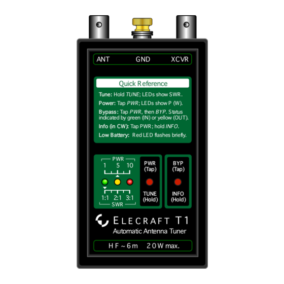
Page 6: Basic Operation
This reduces stress on the final stage. • Do not use the T1 on bands above 54 MHz. Even though the T1 may appear to achieve a low- SWR match on these bands, most of the power will be dissipated in the tuner itself. - Page 7 Tap PWR/TUNE; the yellow LED will flash. Hold BYP/INFO for about 1 second, then release. • The T1 will send several parameters in slow Morse code on both the yellow LED and via a weak RF signal (see page 11). “R” (radix) is used in lieu of decimal points. Parameters sent include: SWR (e.g., S1R0 = 1.0:1)
-
Page 8: Remote Control
(Band IDs for 160-6 meters are 1-11. An ID of 0 is ignored, and an ID of 12 sets L and C to 0. You can verify the band ID received by the T1 using INFO; see page 7.) Figure 3 shows the protocol. -
Page 9: Antenna Considerations
With loaded antennas, you should manually resonate the antenna at the desired center frequency before using the T1 for matching. First, put the T1 into bypass mode as described on page 7. Next, go into TUNE mode and transmit. The T1 will show approximate SWR, allowing you to adjust the coil tap or element length. -
Page 10: Troubleshooting
Try reducing power, recharging the battery, or disconnecting the remote-control cable. T1 fails to find a match, stops tuning, or turns on by itself: Such problems can be caused by RFI due to a poor ground, an end-fed antenna (especially if it’s close to1/2-wavelength long), or an antenna placed close to the transmitter. -
Page 11: Circuit Details
VFO across any band while the T1 sends data (see page 7). Some frequency ranges to try include 1.8-1.9, 3.8-3.9, 7.0-7.2, and 14.0-14.2 MHz. Note: The reason the signal frequency varies from one T1 to the next (and drifts a bit) is that its MCU runs from a ceramic resonator rather than a crystal. Circuit Details (Please refer to the schematic, next page.) The ATU uses seven inductors and seven capacitors in an L-...
Need help?
Do you have a question about the T1 and is the answer not in the manual?
Questions and answers